
 Submit a Paper
 Propose a Special lssue
 Open Access
ARTICLE
Three-Dimensional Printing Conformal Cooling with Structural Lattices for Plastic Injection Molding
1 Singapore Centre for 3D Printing, Nanyang Technological University, 639798, Singapore
2 School of Mechanical and Aerospace Engineering, Nanyang Technological University, 639798, Singapore
* Corresponding Author: Fei Duan. Email:
Frontiers in Heat and Mass Transfer 2024, 22(2), 397-415. https://doi.org/10.32604/fhmt.2024.048984
Received 23 December 2023; Accepted 11 March 2024; Issue published 20 May 2024
 View Full Text
 Download PDF
Abstract
The design of three-dimensional printing based conformal cooling channels (CCCs) in injection molding holds great significance. Compared to CCCs, conformal cooling (CC) cavity solutions show promise in delivering enhanced cooling performance for plastic products, although they have been underexplored. In this research, CC cavity is designed within the mold geometry, reinforced by body-centered cubic (BCC) lattice structures to enhance mechanical strength. Three distinct BCC lattice variations have been integrated into the CC cavity: the BCC structure, BCC with cubes, and BCC with pillars. The thermal performances of the BCC lattice-added CC cavity are assessed numerically after experimental validation. To provide feasible solutions from viewpoints of thermal performances, various BCC lattice structure thicknesses are analyzed in the range of 0.8–1.2 mm. Thermal simulation outcomes reveal that thicker lattice structures enhance mechanical strength but simultaneously lead to an increase in cooling time. Upon examining all the proposed CC cavity solutions supported by BCC, the cooling times range from 2.2 to 4 s, resulting in a reduction of 38.6% to 66.1% when compared to conventional straight-drilled channels. In contrast to CCCs, CC cavities have the potential to decrease the maximum temperature non-uniformity from 8.5 to 6 K. Nevertheless, the presence of lattice structures in CC cavity solutions results in an elevated pressure drop, reaching 2.8 MPa, whereas the results for CCCs remain below 2.1 MPa.Graphic Abstract
Keywords
Injection molding is the most common modern manufacturing method for fabricating plastic parts. It allows for the high-volume production of identical products and items. The raw plastic material is melted in an injection molding machine and then injected into the designed mold, where it is cooled by water or other coolant and hardens at a specific rate to the plastic product [1]. The water or other coolant is cycled around the mold to decrease its temperature. Temperature control of the mold is achieved by cooling systems that also affect the quality of the plastic product [2]. In case of unsatisfied temperature control, a long cooling time is required that results in product quality issues such as plastic shrinkage and warpage [3]. The cooling step is the most time-consuming process of injection molding and the cooling time can occupy up to 70%–80% [4] of the total cycle time. Conformal cooling (CC) is an efficient approach for cooling the plastic injection molding parts while it also achieves uniform temperature distribution [5,6]. A conformal cooling channel is a cooling passage that follows the shape of the mold core or cavity, enabling efficient and consistent cooling during injection molding processes. It generally has a more complex channel design and arrangement than the conventional cooling channel fabricated by traditional machining like drilling. The recent developments in additive manufacturing (AM) and 3D printing techniques allow us to design flexibility so that we can produce complex cooling structures that are exactly the same as designed in computer-aided design (CAD) tools. Hereby, a shorter cooling time and more uniform temperature distribution can be achieved.
Computer-aided engineering (CAE) [7] is a very helpful tool in the design of AM-assisted CC techniques. It has two main steps for the CC design and analysis: (i) CAD for complex design structures and (ii) computational simulations (computational fluid dynamics (CFD) and/or computational structure analysis) for numerical analysis. During the 3D printing process, the CAD-based design can be transferred to the computational simulation environments; then, the final design can be sent to real fabrication. This process proves that the 3D printing process has a strong CAE background. The 3D-printed product flow from CAD to the final design has been used in many studies. Suchana et al. [8–10] conducted the design of experiments (DoE) procedures and carried out CAE-based simulations for the thermo-mechanical simulation and optimization of CC channel in plastic injection molding. The optimal channel design was fabricated by 3D printing machine. The conclusions of all these publications proved that CC channel in injection molding has better cooling performance compared with the traditional straight cooling channel; however, the performance improvement between the CCs and traditional channels is based on the operating conditions and design limitations of the mold. Au et al. [11] proposed CC for the blow molding process. This innovation led to cooling performance enhancement when compared to conventional straight cooling channels. Specifically, they achieved a 40.2% decrease in the maximum part temperature, a 48.9% reduction in part temperature variation, and a 3% decrease in overall cooling time. Using the CAE tools in both design and analysis steps, it was seen that CCs achieved better temperature uniformity [12,13]. Apart from applications, new and different models were also proposed for numerical analysis of the CCs via computational tools. For example, Torres-Alba et al. [14] developed an algorithm that can discrete nodes and temperatures in the mesh structure of the mold; then, they used the data in the generated temperature clusters. Agazzi et al. [15] proposed a methodology based on morphological surfaces to design effective cooling channels for the injection molding process. Furthermore, we conducted CAE-based simulations to investigate the thermal and mechanical performance of a designed conformal cooling channel with various cross-section profiles like circular, elongated, ellipse, and triangular cross-section profiles by using computational environments; then the performance trends were plotted according to the multiple objectives like cooling time, temperature non-uniformity, and pressure drop. The main design variables were water flow rate and inlet temperature, and the obtained performance trends were used in multi-criteria decision-making procedures including neural network metamodels [16,17].
Conformal cooling design is not limited solely to channel-based configurations, it also offers alternative options through cavity structures. Instead of carving cooling channel pathways within the mold, a cavity simply refers to a hollow space within the mold geometry that is filled with coolant. This approach yields superior cooling performance compared to conformal cooling channels. Nevertheless, the primary drawback of the conformal cooling cavity lies in its mechanical performance, and it can also lead to increased temperature non-uniformity due to challenges in adjusting the coolant inlet temperature and flow rate effectively. During the injection molding process, high injection and clamping pressures may cause the mold to crack if its mechanical strength is insufficient. To enhance mechanical performance, supportive structures within the cavity volume can be considered. With the advancements in 3D printing technology, lattice structures have emerged as promising options for these supportive structures [18]. The lattices are cellular materials by repeating the unit cell structures regularly [19]. Maconachie et al. [20] summarized the design properties, mechanical performance, and applications of Selective Laser Melting (SLM) lattice structures. Their analysis proved that lattice structures can be integrated with the conformal cooling cavities to increase mechanical performance. Mercado-Colmenero et al. [21] designed a cooling system with a lattice structure for an injection mold. The geometrical dimensions of the cooling lattice based on the geometrical and manufacturing material properties were optimized by an expert algorithm. They also conducted thermal and mechanical simulations for the cooling system with lattice. The cooling performance and the mechanical structural safety of the lattice structures were analyzed. The innovative conformal cooling system enhances manufacturing efficiency by decreasing cycle times and elevating the quality of produced parts. Brooks et al. [22] designed conformal cooling layers with lattice structures supported, the performance and effectiveness of which were investigated experimentally and numerically. The results revealed the enhanced cooling performance because the existence of lattice structures increases the interfacial surface areas and fluid vorticity. Yun et al. [23] designed cooling channels supported by uniform, increase-type graded, V-type graded, and W-type graded lattice structures. The thermal and structural performance of these cooling channels were analyzed experimentally and numerically. Results showed that the increase-type graded lattice channel had the most stable working surface temperature due to enhanced local convective heat transfer. The V-type lattice channel had poor thermo-fluid performance because of significant volume fraction differences between unit cells, while the W-type graded lattice channel had the lowest maximum stress, thanks to its robust support structure. For the heat transfer performance evaluation of three-dimensional lattice structures, the experimental testing is traditional and is widely used. However, it is expensive and time consuming. Nowadays, there are many numerical investigations on the lattice heat transfer performance based on commercial software and numerical codes. Wang et al. [24] developed a computational model based on Boltzmann method to predict and evaluate the effective heat conductivity of lattice structures with different topologies. Their results found that when the porosity is higher than 0.9, the ETC of different lattice structures were close with each other while when the porosity is lower than 0.9, the structural effect on the ETC became more obvious. Dixit et al. [25] conducted thermal and hydraulic finite element investigations for different types of lattice structures. The effect of porosity of lattice structures was assessed. They found that body-centered-cubic truss, simple-cubic plate, and Kelvin and Octet lattice cells exhibited better thermal performance compared with some microchannel and open-cell foam heat sinks. Lin et al. [26] developed a reduced-order model based on finite element method for evaluating and comparing the thermal performance of seven types of lattice structure cells. The calculation error of this model decreases as the rod aspect ratio increases and the computational efficiency is improved by more than 1000 times. Ernot et al. [27] developed an analytical for predicting the heat transfer performance of multi-layered lattice structures. The results of the analytical model had a good agreement with the CFD simulation results, showing that the analytical model could be quickly and efficiently used for evaluating the thermal performance of multi-layered lattice structures. Yun et al. [28] predicted the heat and stress characteristics of a face-centered lattice channel by using a thermal fluid-structure interaction one way coupled model. Based on the simulation model, the heat transfer and stress characteristics of the FCCZ lattice channel are analyzed by varying the porosity and inlet velocity. Bai et al. [29] and Wang et al. [30] developed numerical models for analyzing the heat transfer performance of lattice core sandwich structures. The numerical results of these researches provided valuable information for the performance of different lattice structures.
In this paper, we presented conformal cooling cavity solutions with different conformal cooling cavity structures, and assessed them according to the thermal and mechanical, performances [31]. Compared to the conformal cooling channels the conformal cooling cavities achieved higher cooling performance (better thermal uniformity and shorter cooling time); lattice structures can help to increase its mechanical performance. The remarkable increment in cooling performance via the conformal cooling cavities motivates us to implement these solutions in real applications. Therefore, in this study, we aim to investigate the cooling performance of the conformal cooling cavities with different lattice structure arrangements on cooling time and temperature uniformity. The referenced mold structure is traditionally manufactured with straight channels which are currently applied in the industry so that its boundary conditions and initial conditions are directly withdrawn from the real plastic injection molding process. For this purpose, we perform CAE-based design and simulation efforts using commercial computational software. The validation of the computational model is provided with the experimental data from the on-site application. The cooling time, temperature non-uniformity, and pressure drop, are chosen as the evaluating criteria. The types, dimensions, and arrangement of different lattice structures are analyzed.
2 Preparation of Lattice Supported Conformal Cooling Cavity Structures
Fig. 1 shows the unit cell of body-centered cubic (BCC) [32] lattice structures used in this study. The BCC designs are inspired from crystal system shapes in crystals and minerals. In the BCC unit cell, the central axis of each round strut is the diagonal of the cubic cell. The supporting structures inside the CC cavity consist of the unit cells repeating in three dimensions. For improving the mechanical properties, two upgraded BCCs are also investigated, i.e., BCC-C and BCC-Z [33] as given in Figs. 1b and 1c. BCC-C adds cubes on the end of the strut and the middle area while BCC-Z adds a pillar in the middle of BCC. With the help of cubes as shown in Fig. 1b, the mechanical properties of the interface between the cavity surface and the strut can be improved. For BCC-Z in Fig. 1c, the pillar in the middle can contribute extra support and lead to the enhancement of mechanical performance. Fig. 1d presents the 3D printed models of BCC and BCC-Z fabricated by direct metal laser sintering (DMLS), which is one of the highest performance to cost ratio 3D printing methods. It employs the focused laser beam to fully melt micron-sized metallic powders. The brand of 3D printing machine is EOS M100. The printing accuracy is 10 microns. The metallic powder size is 15–45 microns.
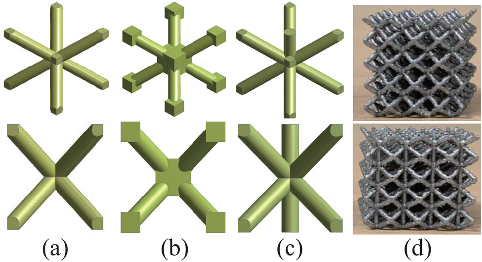
Figure 1: Three unit cell lattice structures used in this study: (a) BCC, (b) BCC-C, (c) BCC-Z, and (d) 3D printed models
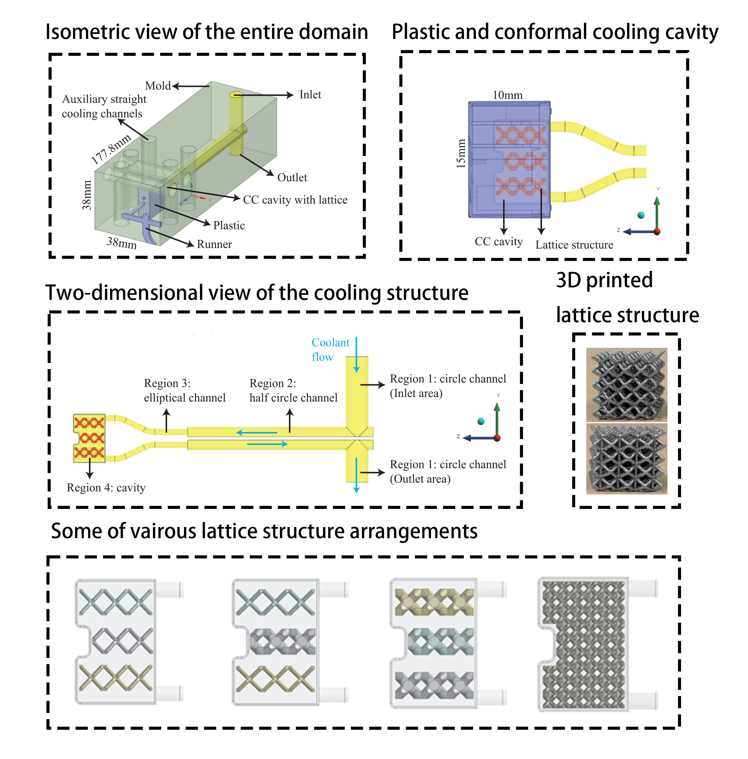
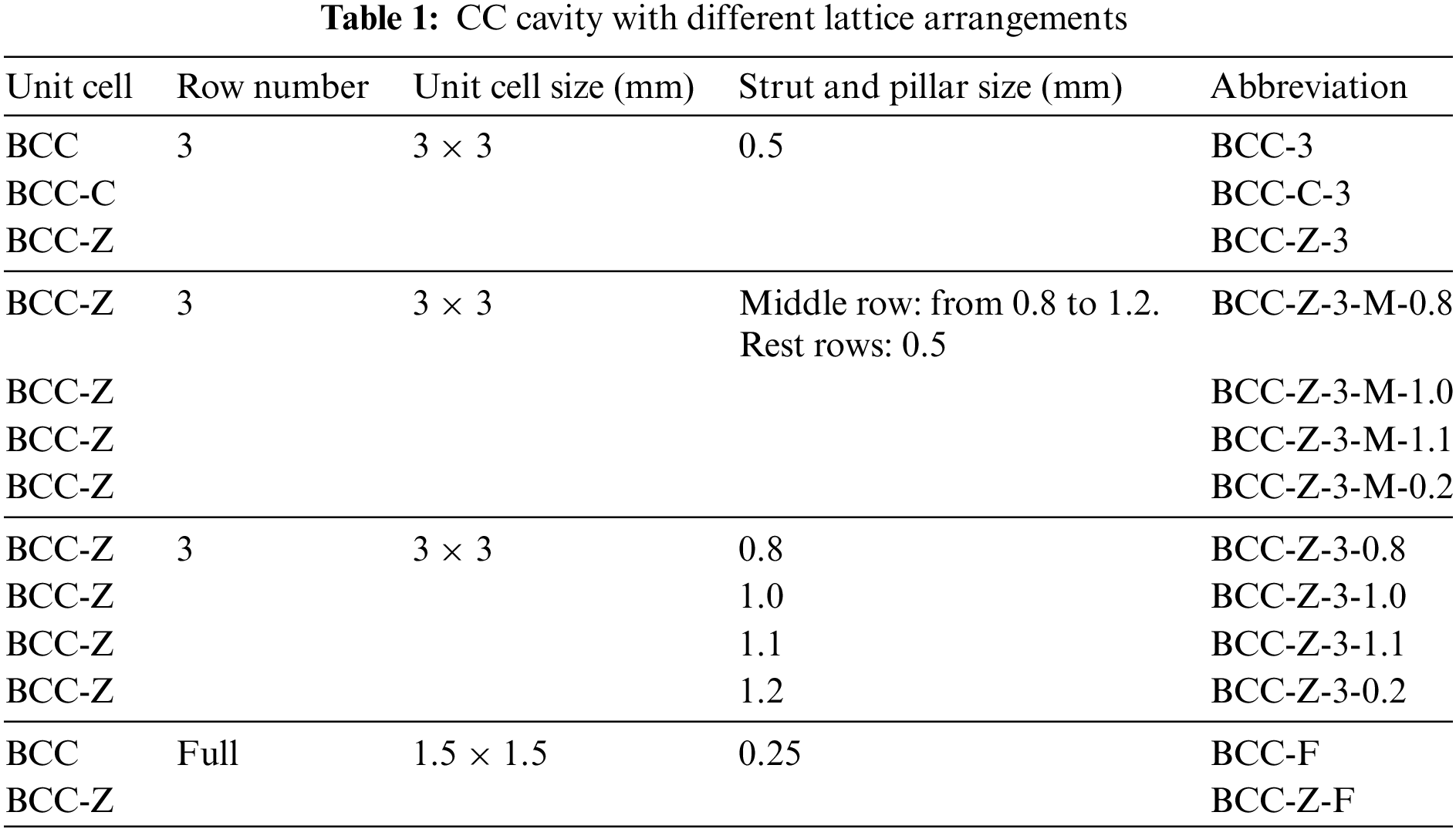
Fig. 2 presents different arrangements of three lattice structures investigated in this study. To simplify the description in the following discussion, different sizes and arrangements of lattice structures are called for the abbreviation given in Table 1. In Fig. 2a, 3 rows of BCC, BCC-C and BCC-Z are inserted for supporting the CC cavity as well as ensuring enough space for water. The purpose of 3 rows of lattice structure is to ensure mechanical strength as well as provide enough cooling space for water. The size of the lattice is fitted with the thickness of the CC cavity as shown from the top view of BCC-Z-3 in Fig. 2a. The end of the struts connects with the walls of the cavity and props up it. Since the mechanical performance of models in Fig. 2a is not satisfied, in Fig. 2b, the strut and pillar of BCC-Z structures in the middle row are thickened from 0.8 to 1.2 mm for stronger mechanical strength. The middle row of lattices are with good mechanical performance, however, the upper and lower two rows are still not satisfied. In Fig. 2c, all the BCC-Z rows inside the CC cavity are thickened from 0.8 to 1.2 mm. This study also investigated the thermal performance of CC cavity full of lattice except for the 3 rows of the lattice. The CC cavity in Fig. 2d is full of lattice structures, which has half size compared with those in Figs. 2a–2c. There are two layers of lattice structures as shown in the top view of Fig. 2d. Fig. 2e presents the BCC-Z structures with different sizes of struts and pillars.
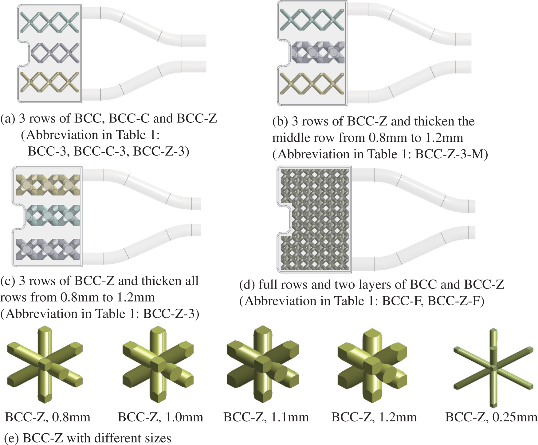
Figure 2: CC cavity with different lattice arrangements
3 Geometric Model for Thermal Simulation
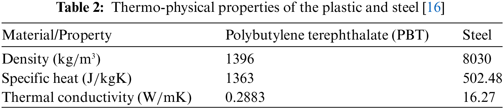
The geometric model for thermal simulation is presented in Fig. 3a, including the mold, plastic product and runner, auxiliary straight cooling channels and CC cavity with lattices. The dimension of the mold is 177.8 mm
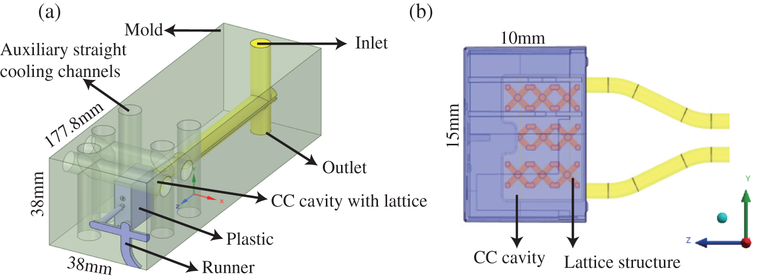
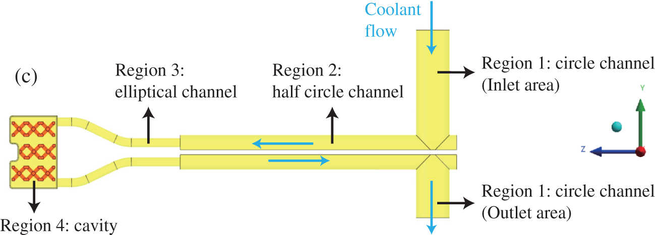
Figure 3: Geometric model for the thermal simulation of the entire plastic injection process: (a) Isometric view; (b) Plastic product, CC cavity and lattice structure; and (c) Cooling channel with CC cavity
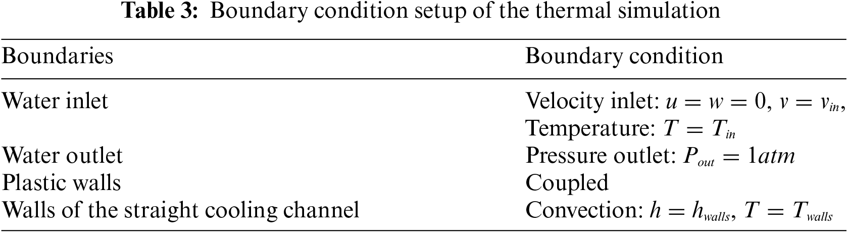
The materials of the plastic product and mold used in this study are polybutylene terephthalate (PBT) and steel, respectively. The thermos-physical properties of the steel and PBT are assumed to be constant and independent of temperature. These values are given in Table 2. The cooling working fluid is water.
ANSYS, Fluent 19.2, is applied to solve the governing equations during the cooling process of injection molding, which is a 3D unsteady heat transfer process. The governing equations include mass, momentum and energy equations given by:
(1) mass equation:
(2) momentum equation:
(3) energy equation:
In these equations,
where
and
where
In the solid mold area, the heat conduction occurs. The corresponding energy equation in this solid part is:
The finite volume method (FVM) is employed to solve the mass, momentum and energy conservation equations by ANSYS Fluent 19.2. The SIMPLEC algorithm is employed to solve the mass and momentum equations during the numerical simulation procedure. And the PRESTO scheme is selected for pressure correction equations. For high accuracy, the second-order upwind is selected as the spatial discretization scheme. The convergence is checked at each time step with the criterion that the scaled residuals are less than
It must be noted that the current study does not consider the polymer flow and its computational boundary conditions. The present computational model starts with the transferred heat from the hot plastic (polymer flow) to the mold geometry. In the case of polymer flow considerations, Eqs. (1)–(8) should also include the polymer flow characteristics. The thermal geometric model is discretized by the tetrahedral mesh as given in Fig. 4. The mesh near the CC cavity area, as shown in Fig. 4b, is refined for enhancing the accuracy when computing the heat transfer between plastics and water. Fig. 5 presents the independent check for mesh numbers and time steps. The thermal simulation process is repeated for different mesh number and different time step. Fig. 5a depicts the decreasing temperature curve with the flow time when the mesh number is increasing from 0.4 million to 2 million. It is noticed that when the mesh number reaches 1.2 million, the decreasing temperature curve does not change anymore, which means the mesh independence is achieved. Thus, all the thermal simulations are conducted with mesh number 1.2 million. Fig. 5b depicts the decreasing temperature curve with the flow time with different time steps. The time step starts from 0.4 s and decreases gradually. When this value is 0.1 and 0.05 s, the respective decreasing temperature curves almost coincide with each other. Thus, for saving computation time, 0.1 s is selected for the thermal simulation.
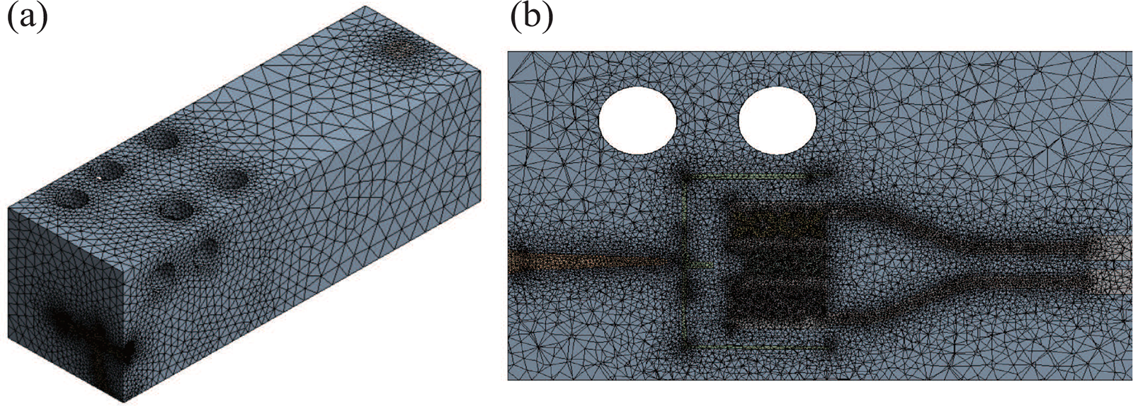
Figure 4: Mesh generated on the thermal geometric model: (a) isometric view, and (b) CC cavity with lattice structures
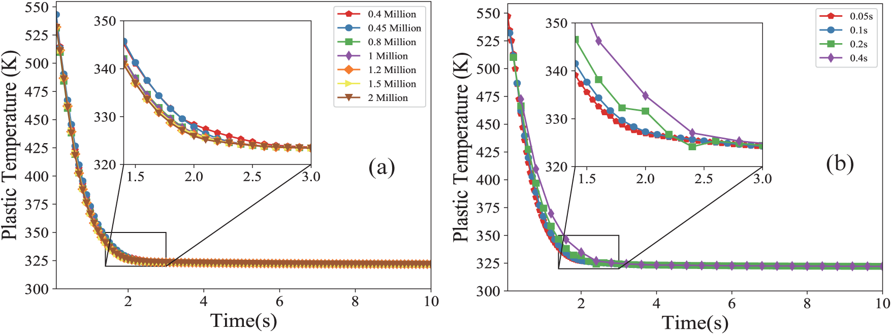
Figure 5: Independent check of Plastic temperature decreasing with time (a) mesh number, and (b) time step
To evaluate the thermal performance of CC cavity, three criteria, cooling time (CT), temperature non-uniformity (TN) and pressure drop (PD), are defined. The CT refers to the time when the maximum temperature of plastic is reduced to the ejection temperature. In this study, the injection and ejection temperatures of injection molding are 543 K (270°C) and 323 K (50°C), respectively. The TN refers to the standard deviation of the plastic surface temperature and smaller TN means the final plastic product has a uniform temperature distribution, which means better temperature uniformity. The result can be computed by Eqs. (9) and (10):
where
The thermal simulation results of the injection molding are compared with the experimental results provided by the collaborator for the validation of the traditional straight channels and real experimental conditions. The traditional straight channel has a cylindrical shape with a cross-sectional diameter of 7 mm. The current operating cooling channel of our industrial collaborator is traditional straight channel and their experiments were carried out by using traditional straight cooling channel. Thus, a thermal simulation was done firstly for the traditional straight cooling channel by using the same simulation setup and boundary conditions. The experimental validation results of cooling time and the plastic temperature after 10 s can be seen in Table 4. The relative error between the experimental data and numerical results are both lower than 10%, which indicates the accuracy of the thermal simulation.
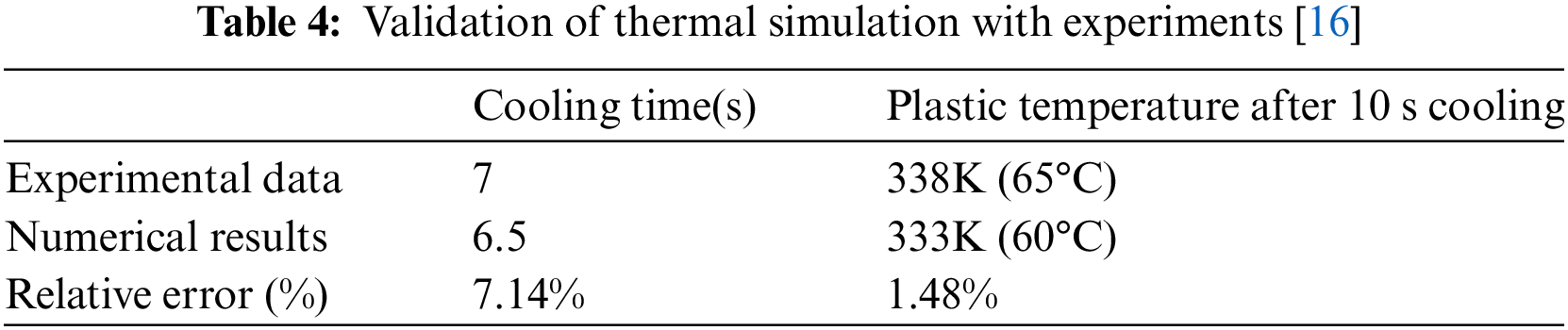
Fig. 6 illustrates the cooling time, temperature non-uniformity, and pressure drop across various lattice configurations within the conformal cooling cavity. Additionally, Fig. 6 provides a visual comparison between the conformal cooling cavities designed in this research and the conformal cooling channels presented in [16]. In Fig. 6a, BCC-3 exhibits the shortest cooling time at 2.2 s, while BCC-Z-3-1.2 and BCC-F have the longest cooling time at 4.0 s. When compared to the traditional straight cooling channel, BCC-3 reduces the cooling time by 66.1% while BCC-Z-3-1.2 and BCC-F reduces the cooling time by 38.6%. The cooling time exhibits a progressive increase from left to right. This phenomenon arises because the available cooling space gradually diminishes due to the lattice structures occupying volume. Specifically, the BCC-3 lattice configuration has thin strut thickness, thereby affording large cooling space for the coolant within the conformal cooling cavity. Conversely, in the case of BCC-Z-3-1.2, the lattice structures within the conformal cooling cavity feature thicker struts and pillars, designed to support the cavity, resulting in a restricted cooling space. Similar considerations apply to the conformal cooling cavity filled with BCC-F. When comparing the conformal cooling cavity with the conformal cooling channel, it becomes evident that the cooling times of structures utilizing BCC-3, BCC-C-3, BCC-Z-3, and BCC-Z-3-M are consistently lower than those observed in any of the conformal cooling channel scenarios. Specifically, the cooling times associated with BCC-F, BCC-Z-3 and BCC-Z-F fall within the range of results obtained from the two conformal cooling channel pathways. The choice of lattice configuration plays a crucial role in determining the cooling efficiency within the conformal cooling cavity. The results suggest that thin strut thickness, as seen in BCC-3, facilitates a more substantial cooling space, leading to shorter cooling times. Conversely, configurations with thicker struts and pillars, such as BCC-Z-3-1.2, limit the available cooling space, resulting in longer cooling times. Additionally, the comparison between conformal cooling cavities and channels highlights the advantages of the former, especially when employing certain lattice arrangements. BCC-3, BCC-C-3, BCC-Z-3, and BCC-Z-3-M demonstrate superior cooling performance within the cavity, surpassing the results achieved in conformal cooling channels. This information can be valuable in optimizing cooling strategies for injection molding.

Figure 6: Comparison of (a) cooling time, (b) temperature non-uniformity, and (c) pressure drop between CC cavity with different lattice arrangements and CC channel designed in [16]
Aside from achieving the shortest cooling time, BCC-3 also exhibits the lowest temperature non-uniformity, as depicted in Fig. 6b. This signifies the most favorable temperature distribution for the end plastic product. The introduction of cubes and pillars into the BCC lattice, such as BCC-C and BCC-Z, gradually increases temperature non-uniformity. This effect becomes more pronounced when thickening the middle row and all three rows in the case of BCC-Z, with slight fluctuations observed. Interestingly, when the conformal cooling cavity is filled with BCC (BCC-F) and BCC-Z (BCC-Z-F), the temperature non-uniformity decreases to less than 5.5 K. Fig. 6b emphasizes that, across all conformal cooling cavity designs, their temperature non-uniformities consistently outperform those of conformal cooling channel designs. This underscores a crucial advantage of conformal cooling cavity design: the ability to maintain a lower temperature non-uniformity, which translates to a more uniform temperature distribution in the final plastic product. In some cases, achieving uniform temperature distribution can be even more critical than minimizing cooling time for ensuring high product quality. From injection molding to 3D printing, having precise control over temperature distribution can result in higher yields, reduced scrap rates, and ultimately, cost savings. Manufacturers can also benefit from increased production efficiency and reduced cycle times, all contributing to enhanced competitiveness in today’s global markets. Achieving low temperature non-uniformity through conformal cooling cavity design is important, as it addresses fundamental concerns related to product quality.
In Fig. 6c, the pressure drop of water within the conformal cooling cavity with various lattice arrangements is depicted. Notably, increasing the thickness of both struts and pillars within the lattice results in a gradual increment in pressure drop. When the conformal cooling cavity is completely filled with BCC-Z (BCC-Z-F), there is a significant spike in the pressure drop. It is worth noting that the pressure drop within the conformal cooling cavity surpasses that observed in the conformal cooling channel. This discrepancy can be attributed to the presence of lattice structures within the cavity, which introduces additional resistance to the flow of water. The lattice structures act as flow obstructions, leading to increased water flow resistance and, consequently, higher pressure drop levels within the conformal cooling cavity compared to the channel configuration. High pressure drop can have significant implications for the overall efficiency of the cooling system. A higher pressure drop means that more energy is required to maintain a consistent flow rate, which can result in increased operational costs and reduced energy efficiency. While lattice structures can improve heat transfer and temperature control, their impact on pressure drop must be managed to avoid excessive energy consumption and potential equipment wear. Careful consideration of these factors is essential to optimize cooling system performance while minimizing operational costs.
Fig. 7 showcases the temperature distribution contours of the plastic product that has undergone a 10-s cooling process within the CC cavity. The featured configurations include BCC-3, BCC-Z-3-M-0.8, BCC-Z-3-0.8, and BCC-F. Evidently, the temperature distribution reveals a noteworthy observation: the plastic product exhibits a hot spot predominantly on its front and top surfaces. Furthermore, it is observed that the extent of the hot spot area increases as certain modifications are introduced. Specifically, when pillars are added within the BCC lattice, when the BCC-Z configuration is thickened, or when the CC cavity is completely filled with BCC structures, there is a noticeable expansion in the area characterized by high temperatures.
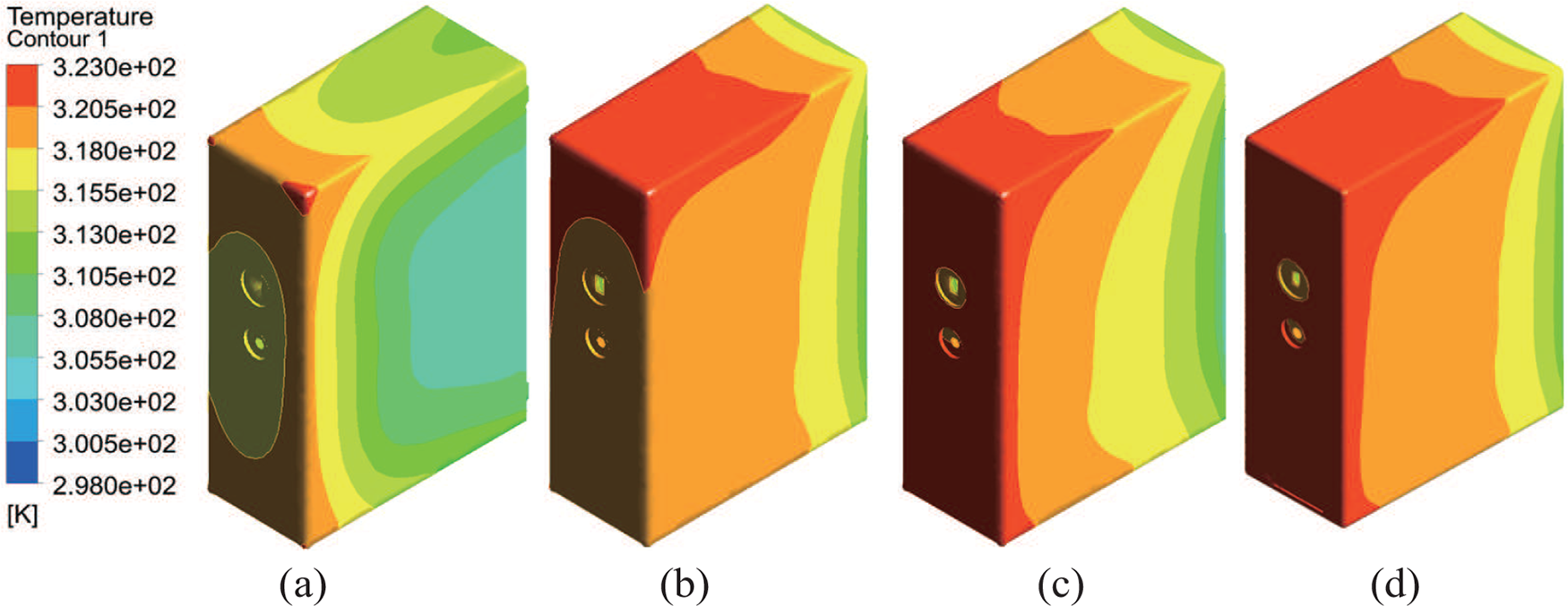
Figure 7: Temperature contour of the plastic product cooled 10-s by CC cavity with different lattice arrangements: (a) BCC-3, (b) BCC-Z-3-M-0.8, (c) BCC-Z-3-0.8, and (d) BCC-Z-F
Fig. 8 gives the average heat transfer coefficient of the convection heat transfer process inside the CC cavity and the fluid volume fraction of CC cavity with different lattice arrangements. It is observed that from BCC-3 to BCC-Z-3-1.2, the average heat transfer coefficient increases gradually while the fluid volume fraction decreases gradually. There is an opposite trend between these two parameters. The first reason is when the fluid volume fraction decreases, there is relatively more space occupied by the lattice structures. This can lead to increased turbulence in the fluid, which, in turn, can enhance the heat transfer coefficient because turbulence promotes better mixing and heat exchange. Additionally, a greater volume of lattice structures aids in the more rapid conduction of heat from the hot region to the cooler one within the system. This enhanced heat conduction can contribute to improved heat transfer coefficients. As proved in Fig. 8, from BCC-Z-3-M-0.8 to BCC-Z-3-1.2, the average heat transfer coefficient grows up gradually. BCC-F has high fluid volume fraction, so the corresponding convection heat transfer coefficient is low. BCC-3, BCC-C-3 and BCC-Z-3 have the highest fluid volume fraction and the lowest heat transfer coefficient. However, while a lower fluid volume fraction does enhance the heat transfer coefficient, it is important to note that a reduction in the fluid volume fraction leads to extended cooling times and elevated pressure drops, both of which have a negative impact on cooling performance, as clearly demonstrated in Figs. 6a and 6c.

Figure 8: Average heat transfer coefficient for CC cavity with different lattice arrangements
A thermal performance factor (TPF) is defined as given in Eq. (11). This straightforward definition allows for a clear and intuitive interpretation between heat transfer coefficient and fluid volume fraction, making it easy to calculate and compare between different cases.
where
As shown in Fig. 9, the highest thermal performance factor is observed at the beginning of the series, with the BCC-C3 configuration. As the lattice arrangement changes, there is a general downward trend in thermal performance factor, with some fluctuations. Notably, there is a significant drop for BCC-F, and then a steady decline thereafter. The different lattice arrangements have a substantial impact on the thermal performance. Overall, this figure can compare the effectiveness of different lattice designs in terms of thermal performance, which could be important for CC cavity applications.
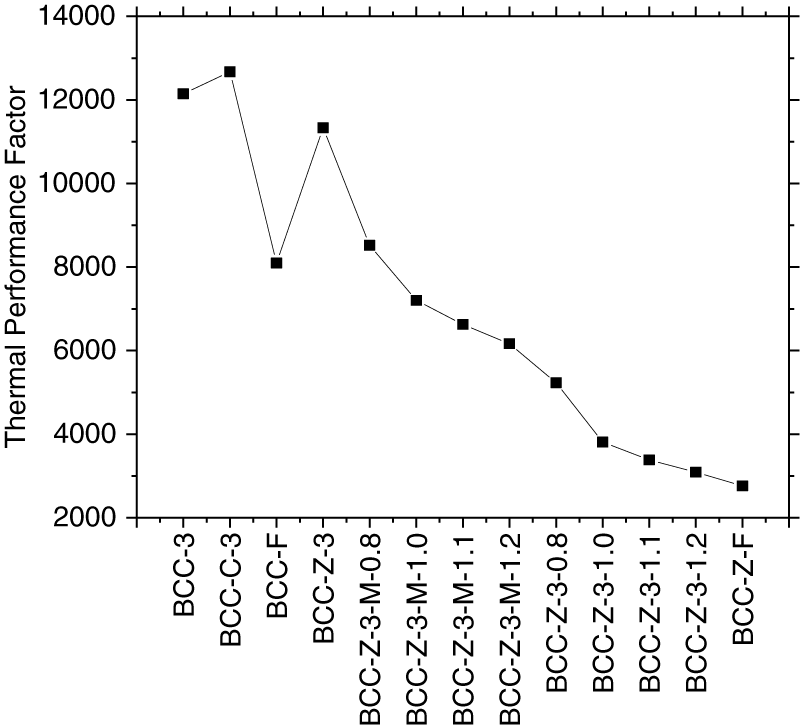
Figure 9: Thermal performance factor for CC cavity with different lattice arrangements
Fig. 10 displays velocity vectors within CC cavities featuring various lattice configurations. When thickening only the middle rows of the BCC-Z lattice within the CC cavity, a discernible effect is the weaker water flow observed at the bottom of the cavity, compared to other regions. This non-uniformity in flow distribution can have implications for temperature control and heat dissipation, which are critical aspects of the cooling process. When all three rows of the BCC-Z lattice inside the CC cavity are thickened, the water flow at the bottom side achieves a more uniform intensity, particularly evident in the case of BCC-Z-3-1.2. This arrangement exhibits remarkably uniform water flow distribution compared to the other three-row BCC-Z arrangements. In contrast, BCC-F and BCC-Z-F, characterized by high flow resistance, display lower water flow velocities compared to the three-row BCC-Z arrangements. Nevertheless, these two configurations exhibit the most uniform flow distribution, which directly correlates with the low temperature non-uniformity observed in Fig. 6b. The ability to maintain uniform flow distribution is a significant advantage as it contributes to consistent temperature control, minimizing temperature differentials and potential defects in the final product. BCC-3, BCC-C-3 and BCC-Z-3 have similar velocity distribution.
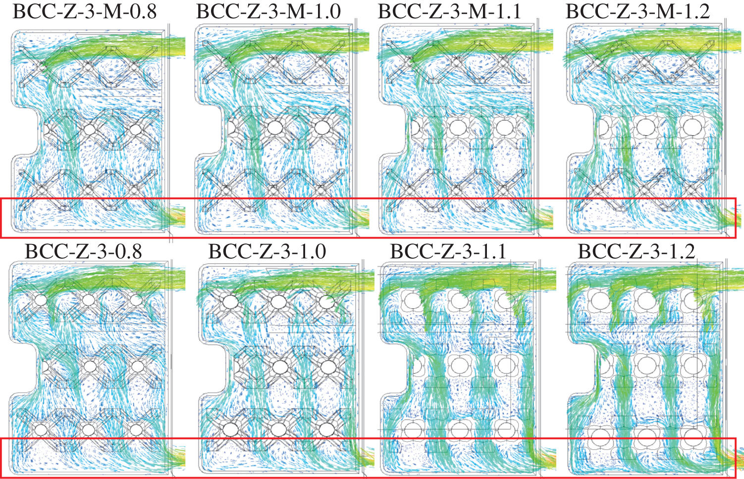
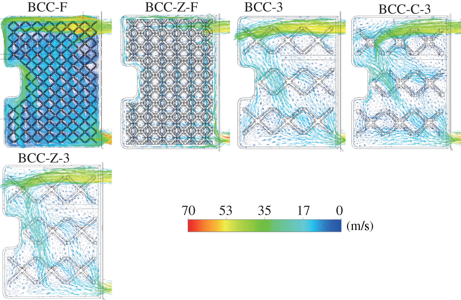
Figure 10: Velocity vectors for CC cavity with different lattice arrangements
In summary, optimizing lattice designs within the CC cavity is a multifaceted process that involves balancing cooling time, temperature uniformity, and flow resistance. These insights into flow patterns and their impact on temperature control underscore the complexity of cooling system design and highlight the need for further research, particularly in terms of mechanical performance, to ensure the viability and effectiveness of these lattice arrangements in practical applications.
In the study, the conformal cooling cavities with different lattice arrangements were designed for cooling the injection molding process of a plastic product. For evaluating the thermal performance of the designed conformal cooling cavities with different lattice structure arrangements, the computational simulations were performed and validated by the experimental results. Three performance criteria that were critical for a real industrial injection molding process (i.e., cooling time, temperature non-uniformity and pressure drop) were defined to assess the conformal cooling cavity with the lattice. Three lattice structures, BCC, BCC-C and BCC-Z, were evaluated. To ensure sufficient cooling space for water, 3 rows of BCC, BCC-C and BCC-Z were considered first. The simulation results showed good thermal performance. Thickening the middle rows and all the 3 rows of BCC-Z decreased the thermal performance. The conformal cooling cavities which were full of small size BCC and BCC-Z were also investigated. The thermal performance was the worse and the pressure drop was higher due to larger space occupation. The cooling times of all the conformal cooling cavities with the structural lattices were between 2.2 to 4 s, which were smaller than the result of the traditional straight cooling channels and conformal cooling channels. Additionally, the temperature non-uniformities of the conformal cooling cavities with the structural lattices were all lower than those of conformal cooling channels. The other advantage of the conformal cooling cavities with the lattice would be easier to prepare through the 3D printing process in comparison with the complex conformal cooling channels.
It was seen that using thick lattice structures to increase mechanical performance could result in additional drawbacks in thermal and hydraulic performance; thus, the best trade-off analysis should be performed carefully to determine the optimum operating conditions. Multi-objective optimization or other multi-criteria decision-making solutions could be applied for the purpose. Moreover, after finalizing the design and before printing out the geometry, the printability of the proposed lattice structures should be checked with the operator to avoid potential on-site printing faults.
Acknowledgement: The authors would like to thank the support of Singapore Centre for 3D Printing (SC3DP) and School of Mechanical and Aerospace Engineering for this original research work. S. Shen thanks the lattice image sharing from Y. Zhou. B. B. Kanbur is the Mistletoe Research Fellow granted by the Momental Foundation.
Funding Statement: The authors received no specific funding for this study.
Author Contributions: The authors confirm contribution to the paper as follows: study conception and design: Suping Shen, Baris Burak Kanbur, Fei Duan; data collection: Suping Shen, Baris Burak Kanbur; analysis and interpretation of results: Suping Shen, Baris Burak Kanbur, Chenlong Wu, Fei Duan; draft manuscript preparation: Suping Shen, Chenlong Wu; manuscript review and editing: Suping Shen, Fei Duan; project administration: Fei Duan. All authors reviewed the results and approved the final version of the manuscript.
Availability of Data and Materials: The data can be provided upon request in case of the agreement with the industrial parter.
Conflicts of Interest: The authors declare that they have no conflicts of interest to report regarding the present study.
References
1. Singh, G., Verma, A. (2017). A brief review on injection moulding manufacturing process. Material Today Proceeding, 4(5), 1423–1433. [Google Scholar]
2. Hassan, H., Regnier, N., Lebot, C., Pujos, C., Defaye, G. (2009). Effect of cooling system on the polymer temperature and solidification during injection molding. Applied Thermal Engineering, 29, 1786–1791. https://doi.org/10.1016/j.applthermaleng.2008.08.011 [Google Scholar] [CrossRef]
3. Hassan, H., Regnier, N., Pijos, C., Arquis, E., Defaye, G. (2010). Modeling the effect of cooling system on the shrinkage and temperature of the polymer by injection molding. Applied Thermal Engineering, 30, 1547–1557. https://doi.org/10.1016/j.applthermaleng.2010.02.025 [Google Scholar] [CrossRef]
4. Shinde, M. S., Ashtankar, K. M., Kuthe, A. M., Dahake, S. W., Mawale, M. B. (2018). Direct rapid manufacturing of molds with conformal cooling channels. Rapid Prototyping Journal, 24(2), 1347–1364. [Google Scholar]
5. Feng, S., Kamat, A. M., Pei, Y. (2021). Design and fabrication of conformal cooling channels in molds: Review and progress updates. International Journal of Heat and Mass Transfer, 171, 121082. https://doi.org/10.1016/j.ijheatmasstransfer.2021.121082 [Google Scholar] [CrossRef]
6. Zink, B., Kovacs, N. K., Kovacs, J. G. (2019). Thermal analysis based method development for novel rapid tooling applications. International Communications in Heat and Mass Transfer, 108, 104297. https://doi.org/10.1016/j.icheatmasstransfer.2019.104297 [Google Scholar] [CrossRef]
7. Kanbur, B. B., Shen, S., Duan, F. (2020). Design and optimization of conformal cooling channels for injection molding: A review. International Journal of Advanced Manufacturing Technology, 106, 3253–3271. https://doi.org/10.1007/s00170-019-04697-9 [Google Scholar] [CrossRef]
8. Suchana, A. J., Wu, T., Zhang, Y., Zhang, J., Tovar, A. et al. (2017). Thermo-mechanical design optimization of conformal cooling channels using de-sign of experiments approach. Procedia Manufacturing, 10, 898–911. https://doi.org/10.1016/j.promfg.2017.07.078 [Google Scholar] [CrossRef]
9. Suchana, A. J., El-Mounayri, H. (2016). Optimal conformal cooling channels in 3D printed dies for plastic injection molding. Procedia Manufacturing, 6, 888–900. [Google Scholar]
10. Suchana, A. J., Wu, T., Shin, Y., Tovar, A., El-Mounayri, H. (2019). Thermo-fluid topology optimization and experimental study of conformal cooling channels for 3D printed plastic injection molds. Procedia Manufacturing, 34, 631–639. https://doi.org/10.1016/j.promfg.2019.06.120 [Google Scholar] [CrossRef]
11. Au, K. M., Yu, K. M. (2013). Conformal cooling channel design and CAE simulation for rapid blow mold. International Journal of Advanced Manufacturing Technology, 66, 311–324. https://doi.org/10.1007/s00170-012-4326-6 [Google Scholar] [CrossRef]
12. Marques, S., Souza, A. F. D., Miranda, J., Yadroitsau, I. (2015). Design of conformal cooling for plastic injection moulding by heat transfer simulation. Polimeros, 25, 564–574. https://doi.org/10.1590/0104-1428.2047 [Google Scholar] [CrossRef]
13. Berger, G. R., Zorn, D., Friesenbichler, W., Bevc, F., Bodor, C. J. (2019). Efficient cooling of hot spots in injection molding. A biomimetic cooling channel versus a heat-conductive mold material and a heat conductive plastics. Polymer Engineering and Science, 59, 180–188. [Google Scholar]
14. Torres-Alba, A., Mercado-Colmenero, J. M., Diaz-Perete, D., Martin-Donate, C. (2020). A new conformal cooling design procedure for injection molding based on temperature clusters and multidimensional discrete models. Polymers, 12, 154. https://doi.org/10.3390/polym12010154 [Google Scholar] [PubMed] [CrossRef]
15. Agazzi, A., Sobotka, V., Legoff, R., Jarny, Y. (2013). Optimal cooling design in injection moulding process-A new approach based on morphological surfaces. Applied Thermal Engineering, 52, 170–178. https://doi.org/10.1016/j.applthermaleng.2012.11.019 [Google Scholar] [CrossRef]
16. Shen, S., Kanbur, B. B., Zhou, Y., Duan, F. (2020). Thermal and mechanical assessments of the 3D-printed conformal cooling channels: Computational analysis and multi-objective optimization. Journal of Materials Engineering and Performance, 29, 8261–8270. https://doi.org/10.1007/s11665-020-05251-5 [Google Scholar] [CrossRef]
17. Kanbur, B. B., Shen, S., Zhou, Y., Duan, F. (2020). Neural network-integrated multiobjective optimization of the 3D-printed conformal cooling channels. Proceedings of the 2020 5th International Conference on Smart and Sustainable Technologies (SpliTech), pp. 1–6. Split, Croatia. [Google Scholar]
18. Hanks, B., Berthel, J., Frecker, M., Simpson, T. W. (2020). Mechanical properties of additively manufactured metal lattice structures: Data review and design interface. Additive Manufacturing, 35, 101301. https://doi.org/10.1016/j.addma.2020.101301 [Google Scholar] [CrossRef]
19. Yan, C., Hao, L., Hussein, A., Bubb, S. L., Young, P. et al. (2014). Evaluation of light-weight AlSi10Mg periodic cellular lattice structures fabricated via direct metal laser sintering. Journal of Materials Processing Technology, 214(4), 856–864. https://doi.org/10.1016/j.jmatprotec.2013.12.004 [Google Scholar] [CrossRef]
20. Maconachie, T., Leary, M., Lozanovski, B., Zhang, X., Qian, M. et al. (2019). SLM lattice structures: Properties, performance, applications and challenges. Material Design, 183, 108137. https://doi.org/10.1016/j.matdes.2019.108137 [Google Scholar] [CrossRef]
21. Mercado-Colmenero, J. M., Martin-Donate, C., Rodriguez-Santiago, M., Moral-Pulido, F., Rubio-Paramio, M. A. (2019). A new conformal cooling lattice design procedure for injection molding applications based on expert algorithms. International Journal of Advanced Manufacturing Technology, 102, 1719–1746. https://doi.org/10.1007/s00170-018-03235-3 [Google Scholar] [CrossRef]
22. Brooks, H., Brigden, K. (2016). Design of conformal cooling layers with self-supporting lattices for additively manufactured tooling. Additive Manufacturing, 11, 16–22. https://doi.org/10.1016/j.addma.2016.03.004 [Google Scholar] [CrossRef]
23. Yun, S., Lee, D., Jang, D. S., Lee, M., Kim, Y. (2021). Numerical analysis on thermo-fluid-structural performance of graded lattice channels produced by metal additive manufacturing. Applied Thermal Engineering, 193, 117204. [Google Scholar]
24. Wang, N., Kaur, I., Singh, P., Li, L. (2021). Prediction of effective thermal conductivity of porous lattice structures and validation with additively manufactured metal foams. Applied Thermal Engineering, 187, 116558. https://doi.org/10.1016/j.applthermaleng.2021.116558 [Google Scholar] [CrossRef]
25. Dixit, T., Nithiarasu, P., Kumar, S. (2021). Numerical evaluation of additively manufactured lattice architectures for heat sink applications. International Journal of Thermal Sciences, 159, 106607. https://doi.org/10.1016/j.ijthermalsci.2020.106607 [Google Scholar] [CrossRef]
26. Lin, S., Cai, J., Xia, H., Ao, X., Liu, J. (2021). A reduced-order model based on fnite element method for fast prediction of thermal performance of lattice structures. International Communications in Heat and Mass Transfer, 126, 105347. https://doi.org/10.1016/j.icheatmasstransfer.2021.105347 [Google Scholar] [CrossRef]
27. Ernot, J., Verdin, P. G., Ahmad, H., Indge, P. (2019). Analytical and numerical predictions of the thermal performance of multi-layered lattice structures. International Journal of Heat and Mass Transfer, 145, 118752. https://doi.org/10.1016/j.ijheatmasstransfer.2019.118752 [Google Scholar] [CrossRef]
28. Yun, S., Kwon, J., Lee, D., Shin, H. H., Kim, Y. (2020). Heat transfer and stress characteristics of additive manufactured FCCZ lattice channel using thermal fluid-structure interaction model. International Journal of Heat and Mass Transfer, 149, 119187. https://doi.org/10.1016/j.ijheatmasstransfer.2019.119187 [Google Scholar] [CrossRef]
29. Bai, X., Zheng, Z., Nakayama, A. (2019). Heat transfer performance analysis on lattice core sandwich panel structures. International Journal of Heat and Mass Transfer, 143, 118525. https://doi.org/10.1016/j.ijheatmasstransfer.2019.118525 [Google Scholar] [CrossRef]
30. Wang, X., Zeng, T., Xu, G., Zhang, K., Yu, S. (2021). Predicting the equivalent thermal conductivity of pyramidal lattice core sandwich structures based on Monte Carlo model. International Journal of Thermal Sciences, 161, 106701. https://doi.org/10.1016/j.ijthermalsci.2020.106701 [Google Scholar] [CrossRef]
31. Kanbur, B. B., Shen, S., Zhou, Y., Duan, F. (2020). Thermal and mechanical simulations of the lattice structures in the conformal cooling cavities for 3D printed injection molds. Material Today Proceeding, 28, 379–383. https://doi.org/10.1016/j.matpr.2019.10.017 [Google Scholar] [CrossRef]
32. Misra, P. K. (2012). Physics of condensed matter, pp. 1–35. USA: Adademic Press. [Google Scholar]
33. Maskery, I., Hussey, A., Panesar, A., Aremu, A., Tuck, C. et al. (2017). An investigation into reinforced and functionally graded lattice structures. Journal of Cellular Plastics, 53(2), 151–165. https://doi.org/10.1177/0021955X16639035 [Google Scholar] [CrossRef]
34. Ye, W., Pan, Y., He, L., Chen, B., Liu, J. et al. (2021). Design with modelling techniques. In: Industrial ventilation design guidebook, pp. 109–183. Cambridge, Massachusetts, USA: Academic Press. [Google Scholar]
35. Hsu, F. H., Wang, K., Huang, C. T., Chang, R. Y. (2013). Investigation on conformal cooling system design in injection molding. Advances in Production Engineering and Management, 8(2), 107–115. https://doi.org/10.14743/apem2013.2.158 [Google Scholar] [CrossRef]
36. Hsu, F. H., Wu, B. H., Huang, C. T., Chang, R. Y. (2014). Cooling effects study by considering a turbulence model in injection molding. AIP Conference Proceeding, vol. 1593, pp. 615–618. Nuremberg, Germany. [Google Scholar]
Cite This Article
 Copyright © 2024 The Author(s). Published by Tech Science Press.
This work is licensed under a Creative Commons Attribution 4.0 International License , which permits unrestricted use, distribution, and reproduction in any medium, provided the original work is properly cited.
 Downloads
 Citation Tools