
 Submit a Paper
 Propose a Special lssue
 Open Access
ARTICLE
An Experimental and Numerical Thermal Flow Analysis in a Solar Air Collector with Different Delta Wing Height Ratios
1 Department of Mechanical Engineering Shahrood Branch, lslamic Azad University, Shahrood, Iran
2 Airflow Sciences Corporation, Livonia, MI, USA
3 School of Civil and Mechanical Engineering, Curtin University, Bentley, Australia
4 Department of English as an Additional Language (EAL), Heriot-Watt University, Galashiels, Scotland
* Corresponding Authors: Ghobad Shafiei Sabet. Email: ; Ahmad Fakhari. Email:
Frontiers in Heat and Mass Transfer 2024, 22(2), 491-509. https://doi.org/10.32604/fhmt.2024.048290
Received 04 December 2023; Accepted 29 January 2024; Issue published 20 May 2024
 View Full Text
 Download PDF
Abstract
This study conducts both numerical and empirical assessments of thermal transfer and fluid flow characteristics in a Solar Air Collector (SAC) using a Delta Wing Vortex Generator (DWVG), and the effects of different height ratios (R = 0.6, 0.8, 1, 1.2 and 1.4) in delta wing vortex generators, which were not considered in the earlier studies, are investigated. Energy and exergy analyses are performed to gain maximum efficiency. The Reynolds number based on the outlet velocity and hydraulic diameter falls between 4400 and 22000, corresponding to the volume flow rate of 5.21–26.07 m/h. It is observed that the delta wing vortex generators with a higher height ratio yield maximum heat transfer enhancement and overall enhancement ratio. The empirical and numerical findings demonstrate that the exergy and thermal efficiencies decline in a specific range. The Nusselt number, pressure drop, energy, and exergy efficiencies enhance with rising Reynolds number, although the friction coefficient diminishes. The maximum heat transfer enhancement is 57%. According to the evaluation of exergy efficiency, the greatest efficiency of 31.2% is obtained at R = 1.4 and Reynolds number 22000.Keywords
Nomenclature
| Collector aperture area | |
| Top glass cover’s specific heat capacity | |
| Specific heat capacity of air | |
| Hydraulic Diameter (m) | |
| The rate Energy | |
| The rate of exergy | |
| Irreversibility or exergy destruction rate | |
| ep | Vortex Generator pitch ratio |
| Friction factor coefficient | |
| Effective sun irradiation on the collector’s surface | |
| Collector Length feature (m) | |
| Air mass flow rate (kg/s) | |
| Nusselt number ( | |
| Nusselt number of reference collector | |
| Nusselt number ratio ( | |
| Pressure | |
| The universal gas constant | |
| Reynolds number ( | |
| Height ratio | |
| Entropy | |
| T | The temperature at the periphery |
| The component of velocity in the corresponding direction | |
| Feature of length | |
| Boltzmann’s constant | |
| Heat flux receive on the surface from the surroundings | |
| Greek Letters | |
| Transmittance of the transparent cover | |
| Thermal expansion coefficient | |
| Rate of plate absorption | |
| Dissipation rate of turbulent kinetic energy | |
| Heat absorber plate emissivity | |
| The emissivity of the top glass cover | |
| Thermal efficiency | |
| Exergy performance | |
| Glass cover thermal conductivity coefficient ( | |
| Dynamic viscosity | |
| Density ( | |
| Emissivity | |
| Turbulent Viscosity | |
| Turbulent Prandtl number for kinetic energy | |
| Turbulent Prandtl number for dissipation | |
| Subscripts | |
| e | Environment |
| FDWVG | Flat Delta-Wing Vortex Generator |
| f | Friction Factor |
| FVM | Finite Volume Method |
| f | Fluid |
| in | Inlet |
| OER | Overall Enhancement Ratio |
| out | Outlet |
| PP | Pumping Power |
| s | Sun |
| sol | Solar |
| SAC | SAC |
| VGs | Vortex Generators |
In regards to renewable energy, solar energy would seem the most viable due to its plentiful nature and continuous environmental impact. The solar air heater is economically feasible due to its low cost, basic design and minimal upkeep. As an energy-producing device, it absorbs solar thermal energy by gripping the surface and converting it into hot air.
Various advanced approaches to preserving solar energy for heating purposes are employed extensively to decrease the reliance on fossil fuels in the winter [1]. There are several mechanisms for converting solar energy into other forms such as photo biochemical, photothermal and photo voltaic.
Photothermal conversion mechanisms are divided into passive and active. The flow can be heated passively without requiring any external energy source. Heating a building, drying crops, and heating water inside a tank are examples of passive methods. In active methods of converting photothermal energy, heating the flow is done by using the energy inputs of the main system. Among the most common active methods are solar collectors, pools, and power plants [2].
A SAC takes advantage of the sun’s energy by absorbing it through its surface and converting it into warm air. Due to the high thermal resistance between the absorber and air, it has poor thermal efficiency [3].
Solar air collector is used in many heating applications, such as heating the buildings’ space, drying agricultural products, timber drying, industrial applications, etc., Solar air collectors are affordable and have a wide range of applications. Solar air collectors are environmentally friendly, pollution-free, portable, financially competitive, and safe. Mainly due to the heat transfer coefficient, the displacement of the bottom of the absorber plate and the circulating flow leads to higher temperature of the plate and more heat loss. In order to improve the efficiency of solar air heaters by using different designs of flow regimes such as porosity and artificial roughness, several efforts have been made. Solar collectors are divided into two types depending on the working fluid: liquid collectors and air collectors [4]. Agriculture, wood, biomass cultivation, waste biomass, construction materials, and many other products are dried with SACs [5,6]. Despite the advantages that conventional drying techniques may possess, they are associated with certain drawbacks, including the risk of contamination, low productivity, and detriment to product quality. Air collectors powered by the sun can be deployed to ventilate agricultural storehouses or industrial areas, act as passive solar chimneys, supply warmth to greenhouses, and fulfill many other needs for hot air [7,8].
There has been increasing interest in improving the thermal performance of SACs by altering the design and application of these devices [9]. Choi et al. [10] conducted an analytical investigation of solar air heating devices for a home, using a concrete foundation as a form of heat storage. The heat stored in the concrete foundation during daylight hours could be utilized more effectively during the evening. The base concrete was found to absorb 13.2% less heat when insulated, leading to an increase of 12% in the amount of heat released; thereby demonstrating the necessity of insulation for such models.
Yu et al. [11] examined the heating system for a residential home by combining a hollow wall and a SAC. The efficacy of the system was evaluated by monitoring thermal performance, and the effects of relevant parameters were examined. The system reduced the indoor air temperature significantly, thus eliminating the need for night heating, according to the results.
An experimental investigation on the impact of different factors of protrusion, such as configuration, location, and height on heat transfer augmentation was looked into on the solar air heater duct by Aman et al. [12]. They have reported that the spherical protrusion yields higher heat transfer performance. In comparison to the smooth case, the Nusselt number is 3.9 times greater and the friction factor is 1.8 times greater for e/D = 0.036, w/W = 0.166, and ψ = 1. They have provided Nusselt number and friction factor correlations to assess the effectiveness of solar air heaters.
When heat transfer properties are affected by flow and velocity patterns, it is vital to study ways to improve thermal exchange between the absorber and the air flow. The creation of a boundary layer on the area of the absorber has an instantaneous effect on heat exchange, with an augmentation of the boundary layer, resulting in a diminishment in the heat transferred [13]. Solar air collector temperature reduces when heat transfer between the absorber and air flow enhances. In other words, it optimizes the efficiency of collector and reduces the heat loss as a result. Thus, numerous factors, such as absorber size and material, wind speed, air temperature, flow properties, glass covering type, and insulation thickness, have the greatest impact on collector efficiency. Several studies have investigated the effectiveness of artificial roughness and corrugated plates in improving the heat transfer rate between the absorber and the air flow in SACs [14,15]. Sari et al. [16] investigated the effects of a combination of protrusion and baffles on the achievement of SACs. The results showed that compared to a smooth case, the energy and exergy efficiencies of a SAC with three pairs of protrusion and baffles increased by an average of 7.4% and 12%, respectively.
The implementation of the protrusion resulted in an increase in both exergy and thermal efficiency due to the production of greater turbulence and the elimination of the vortices created in the corners of the SAC.
Karim et al. [17] developed mathematical models and performed simulations of a counter-flow v-groove collector with MATLAB program and conducted a parametric analysis of solar radiation to determine the influence of intake and exit temperatures, collector length, and mass flow on SAC efficiency. Zhu et al. [18] presented an empirical and theoretical study of micro-heat pipe arrays on flat-plate solar collectors, analyzing heat transfer and collector coefficient of friction, and assessing the impacts of weather and process parameters on thermal performance, air temperature, and energy loss. It was observed that when the volume flow rate was set at 290 m3/h, the performance of the collector rose to a significant degree, reaching 69%.
The evaluation of the thermal efficiency of a flat plate SAC has been reported by Agathokleous et al. [19]. The most important characteristics of collector innovation are simple design methods and cost-saving materials.
In our previous work, four collectors with different baffle arrangements have been numerically and experimentally investigated. Among them, case A was chosen as the optimum collector for the installation of the wing vortex generators on the surface of the absorber. Furthermore, the flat wing vortex generator and perforated wing vortex generator in collector type A at different pitch ratios have been examined. The use of a large attack angle of 45° improved heat transfer, energy and exergy efficiencies [16,19,20].
The above review has demonstrated that a wide variety of numerical and experimental research has been done to organize the utilization of longitudinal wings and winglets for heat transfer. However, there have been very few investigations into the effects of the height ratio Rh of wing or winglet vortex generators on SACs.
In our previous studies, such as [16] and [20], we noticed that energy losses are significant, and changing the parameters of the wing or winglet significantly boosts the achievement of the SAC, hence in this work, optimization of the efficienty, and minimization of the energy losses are targeted.
The current work is a continuation of our earlier investigations. In this study, the Flat Delta Wing Vortex Generators (FDWVG) with different height ratios Rh are fixed on the absorber of the SAC. To improve the exergy and energy performance and thermal achievement of the SAC, the optimal results such as the wing angle of attack and baffles arrangement of our previous studies have been utilized.
2 Empirical Setup and Procedure
2.1 SAC Structural Specifications
The case study in this work is a rectangular SAC with the dimension of 1000 L × 800 W × 100 H (mm3) which is made of a galvanized metal plate with a thickness of 1 mm as illustrated in Figs. 1a and 1b. The empirical apparatus comprises (1) blower, (2) inlet pipe, (3) Digital Thermometer, (4) digital pressure gage, (5) collector frame, (6) Flat Delta Wing Vortex generator, (7) glass cover, (8) baffle, (9) Solar Power Meter, (10) Absorber, (11) Anemometer, (12) outlet pipe, (13) degree adjustment, (14) collector support or chassis, (15) Thermocouple (16) thermocouple setup.
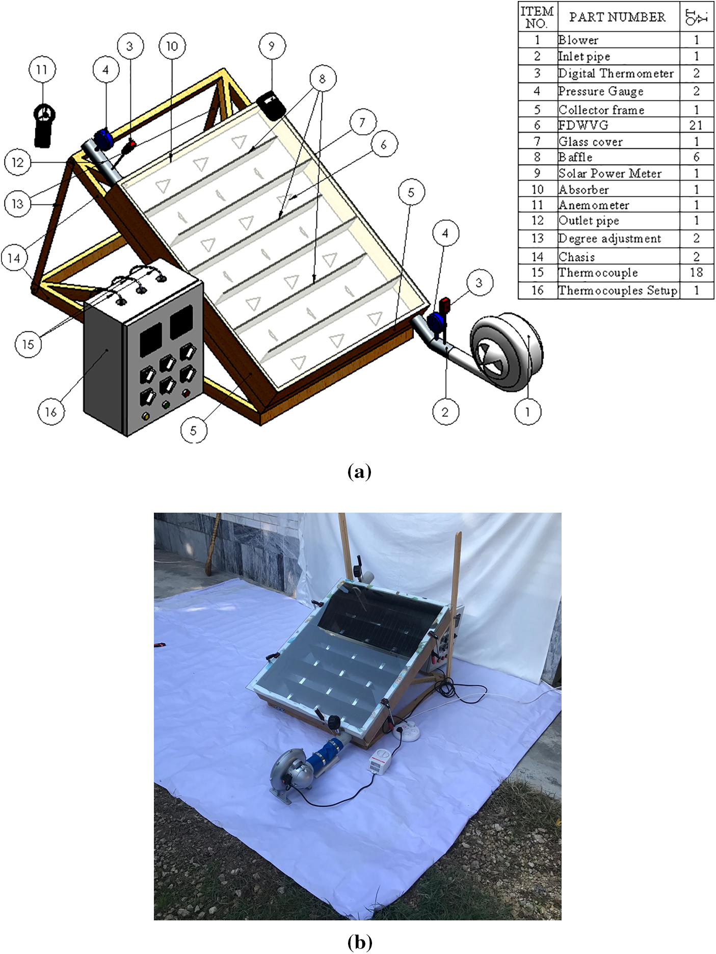
Figure 1: (a) Schematic of the setup, (b) An image of the experimental setup
The radial blower (item 1) has a capacity of 0.5 KW and discharges air from the blower through the inlet pipe (item 2) with a diameter of 63.5 mm. In order to record the inlet and exit temperature, two digital Thermometers (item 3) are attached. Also, the pressure loss of the inlet and exit of the collector is determined by two VSI VM281 digital pressure meters (item 4). To detect the temperature of the surface, eighteen PT100 K-type thermocouples (item 15) are mounted at the bottom of the SAC. The heat flux radiation from the sun is measured with the TES 1333 Solar Power Meter (item 9) which is mounted at the outside of the SAC. Furthermore, the air velocity at the SAC outlet is measured using a Prova AVM-301 anemometer (item 11). The baffles with dimensions of L × H = 100 mm × 700 mm and crafted of polycarbonate with a thickness of 3 mm are installed inside the SAC. The test section is isolated by wood and glass wool, hence the amount of heat loss from channel walls, collector bottom, and surfaces of the inlet and outlet has not been significant. In addition, due to the isolation, the heat loss to the environment has been negligible.
2.2 Vortex Generator Configuration
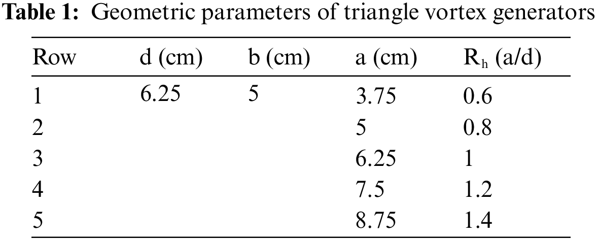
To make the absorber surface rough, FDWVGs are glued to the absorber of the collector. A schematic of the absorber with VGs is depicted in Fig. 2. The vortex generator (VG) angle of attack with the absorber surface is referred to as the angle of attack. According to the previous result of our study [20], the values of the vortex generators-pith ep = 0.55, angle of attack α = 45° and the VGs width of 50 mm were kept fixed. More information about the geometrical parameters can be found in Table 1.
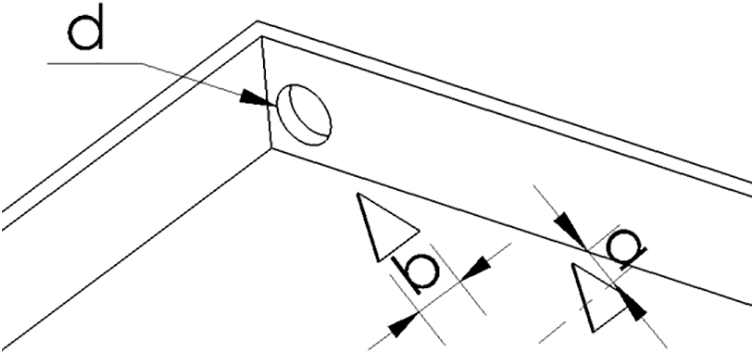
Figure 2: Vortex generator setup
3 Data Reduction and Uncertainty Analysis
In the current investigation, thermal characteristics, energy and exergy efficiencies, and the Overall Enhancement Ratio (OER) in the SAC are determined. The thermal energy balance is established by contrasting air enthalpy with the heat provided from outside. The thermal energy gained by the absorber plate may be written as
In order to calculate the heat transfer coefficient, Newton’s law of cooling, expressed by Eq. (2), is applied:
where A is the absorber area:
The experimental Nusselt number is determined by
The Reynolds number (Re) is defined as
The value of the friction factor is derived as
∆P expresses the pressure drop along the length of the collector and can be written as ∆P = Pin – Pout, where Pin and Pout are the inlet and outlet pressure respectively. Additionally, ρ, u, L, and D denote the density of the fluid, the velocity of the fluid, the length, and the hydraulic diameter of the collector, respectively. All the thermophysical parameters of air utilized at bulk temperature Tbulk = (Tin + Tout)/2 in both numerical and empirical procedures.
To determine the practical use of the augmented SAC, the performance of the SAC is estimated vs. the plain absorber at the same PP in the form of Overall Enhancement Ratio (OER) is assessed using the equation given by
The collector thermal efficiency (ηe) is one of the most essential factors in this investigation. It can be determined as [21,22]
where the mass flow rate is represented by
where the temperatures of the sun and the environment, are denoted as Ts and Te, respectively.
Exergy destruction generally occurs because of irreversibility (due to the temperature difference, or sudden expansion), within a component system, and is an internal phenomenon that can be derived as follows:
The uncertainty analysis is performed to estimate the errors in calculated parameters. Non-dimensional parameter uncertainties are ±5% for the Nusselt number, ±5 for the Reynolds number, and ±7 for friction. Table 2 shows the uncertainty values for various instruments employed in the current investigation. Fig. 3 shows the procedure of investigation of the current study.
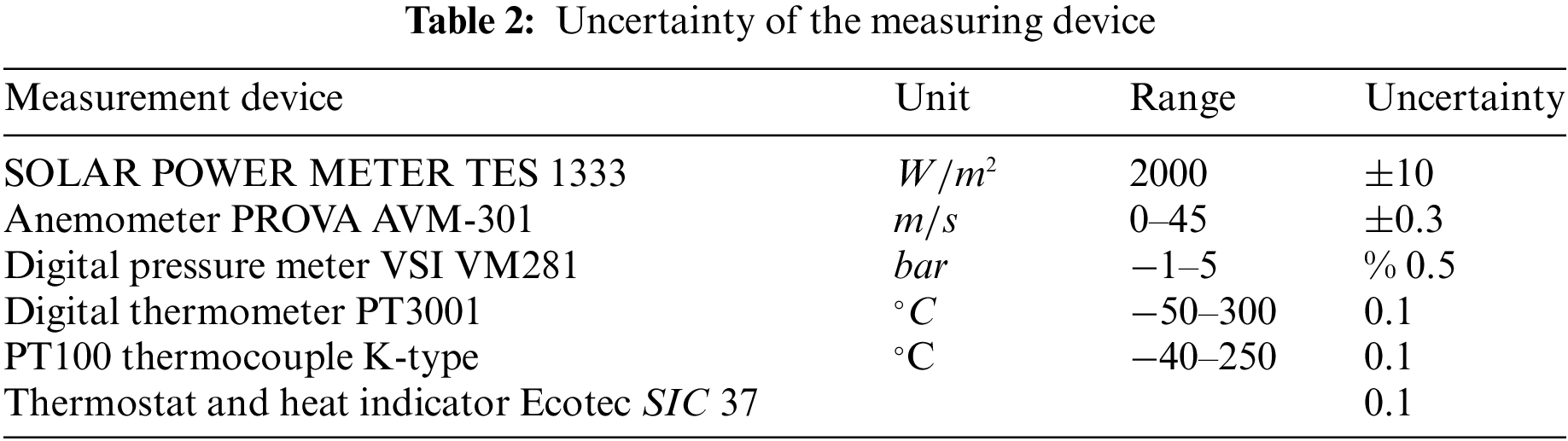
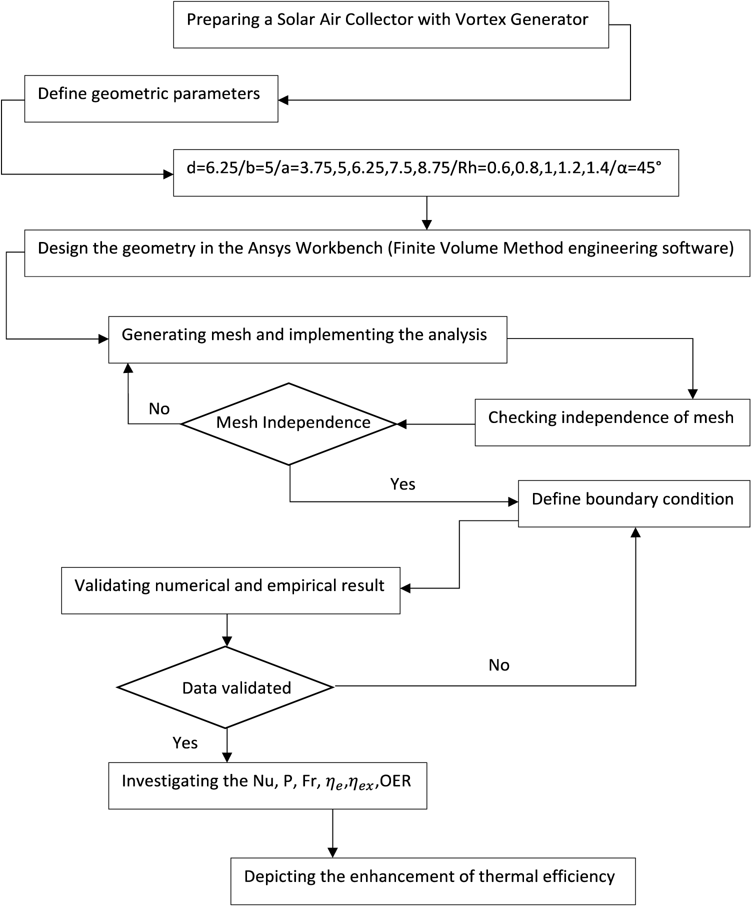
Figure 3: The investigation procedure in the current study
A numerical study is conducted in this research to compare the experimental data with the numerical results. Numerical simulations were done using ANSYS-FLUENT 13, which uses FVM to solve fluid flow equations. It is based on turbulent flow inside SAC and the k-ϵ model is accurate for both planer and round jets. The standard k-ϵ model solves two distinct transport equations of turbulent kinetic energy k, and dissipation ϵ, enabling the independent determination of turbulent velocity and length scales [25]:
and,
In which,
Heat transfer from radiation was simulated using the S-2-S model; which considers only surface to surface radiation. The outgoing heat flux from a specific surface s consists of both directly emitted and reflected heat. The amount of reflected heat is influenced by the incoming heat from the surrounding environment, and this can be described in relation to the heat flux departing from all other surfaces. The heat that bounces off the surface can be written as
where
For the investigation, the following assumptions were made:
• Heat loss from channel walls, collector bottom, and surfaces of inlet and outlet not considered because of the isolation.
• The absorber does not emit any long-wave radiation outside of SAC.
Numerical simulations were done using ANSYS-FLUENT 13, which uses FVM to solve fluid flow equations. It is based on turbulent flow inside SAC and the k-ϵ model is accurate for both planer and round jets. Heat transfer from radiation was simulated using the S-2-S model. A cluster of 40 face cells was established on a glass surface in order to reduce the amount of time needed for calculations and guarantee dependable precision for the simulation. The mesh density for various elements is shown in Fig. 4. Improvement of mesh was performed around the FDWVG, baffles, and absorber due to the vital role of computation. According to Table 1, the mesh spacing of the FDWVG, Baffles, and absorber are b/50, b/17, and b/17, respectively.
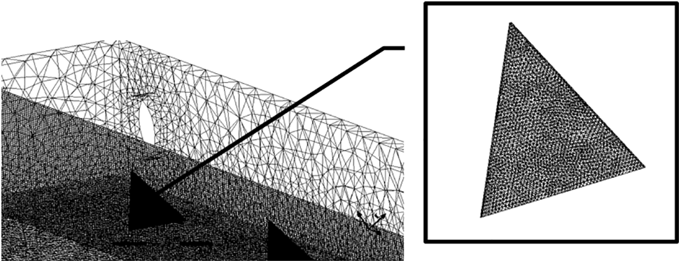
Figure 4: Generated mesh for the numerical simulation
4.1 Analysis of the Mesh Independency
To perform grid independence analysis, the simulations were initiated with a mesh size of 290000 cells, and the mesh resolution was refined approximately 1.3 times each time. Finally, the cases with 290000, 370000, 480000, 590000, 84000 were examined for the independency analysis. The averaged Nusselt number
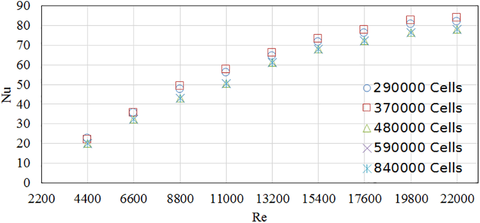
Figure 5: Independency of numerical results from mesh numbers
4.2 Boundary Conditions and Material Properties
Fig. 6 shows the boundary conditions for the computational domain. The Boussinesq approximation has been utilized to determine the density of the air. Wall function has also been applied to the walls.
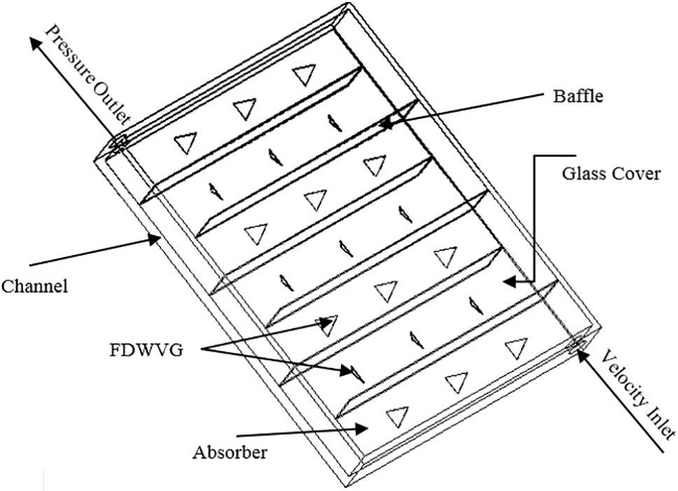
Figure 6: The computational domain and the boundaries
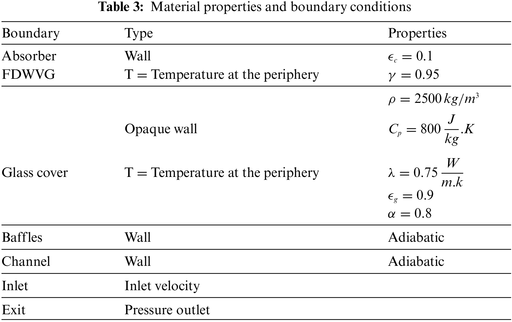
An example of Boussinesque approximation, a review and some information about wall functions, their applications and optimizations can be found in [26–28]. The boundary conditions and material characteristics are presented in Table 3.
4.3 Validation of Numerical Model
Several tests were performed in order to verify the numerical results with empirical data that have been collected. Data from experiments, such as velocity and temperature were converted to non-dimensional values and compared to numerical simulation. Fig. 7 presents the average Nusselt number at different points of the absorber, and compares the numerical and experimental outputs to validate our numerical simulations with our experiment and also the experiment by Sari et al. [20]. There is a marginal discrepancy between the numerical simulation and empirical data of 9%, which shows that they are in good agreement.
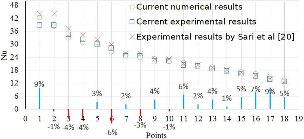
Figure 7: Validation of numerical results and experimental data (The points are the used thermocouples below the collector)
4.4 Numerical Results and Discussion
The performance of the SAC is evaluated numerically in this section, along with simulation results. The influence of Rh on the flow patterns, temperature distribution, pressure drop, and thermal and exergy efficiencies of the collector is also investigated. The Rh of the VGs ranges from 0.6 to 1.4 with height ratio of 0.6, 0.8, 1, 1.2, and 1.4. There were three VGs in each way. The angle of attack was set to 45°. The volume flow rate fluctuated between 5.21 to 26.07
4.5 Effect of Using Different Heights of FDWVG
The variation of Nu vs. Re of the glass and absorb at different height ratios Rh = 0.6, 0.8, 1, 1.2, and 1.4 is presented in Figs. 8a and 8bto estimate the impact of height ratio on heat transfer. As expected the Nu increase with Re. These findings are consistent with those of our earlier research [16,20]. The comparison reveals that the Nu of the glass and absorber with FDWVG is higher than the smooth case. As can be observed, the Nu rises as the height ratio rises. This is because the larger height ratio (Rh) produces strong flow circulation and separation, which leads to higher turbulence intensity, resulting in heat transfer enhancement [29].
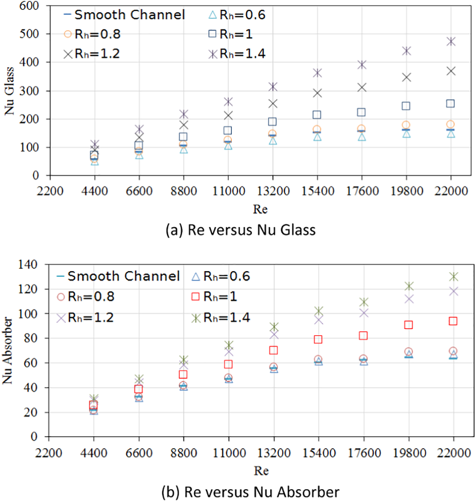
Figure 8: (a) Effect of height ratio on Nusselt number of glass with Re, (b) Effect of height ratio on Nusselt number of absorber with Re
Fig. 9 depicts the pressure drop vs. mass flow rate for smooth and rough cases. The pressure drop increases, as predicted, by enhancing the flow rate in both cases. The pressure drop values for collectors with vortex generators are considerably greater than those for smooth collectors. The collector with a higher height ratio Rh = 1.4 yields a higher pressure drop. The collector roughened with different height ratios of the vortex generators; Rh = 0.6, 0.8, 1, 1.2, and 1.4, supplies the average pressure drop greater than the smooth one by around 4%, 9%, 29%, 45%, and 50%, respectively.
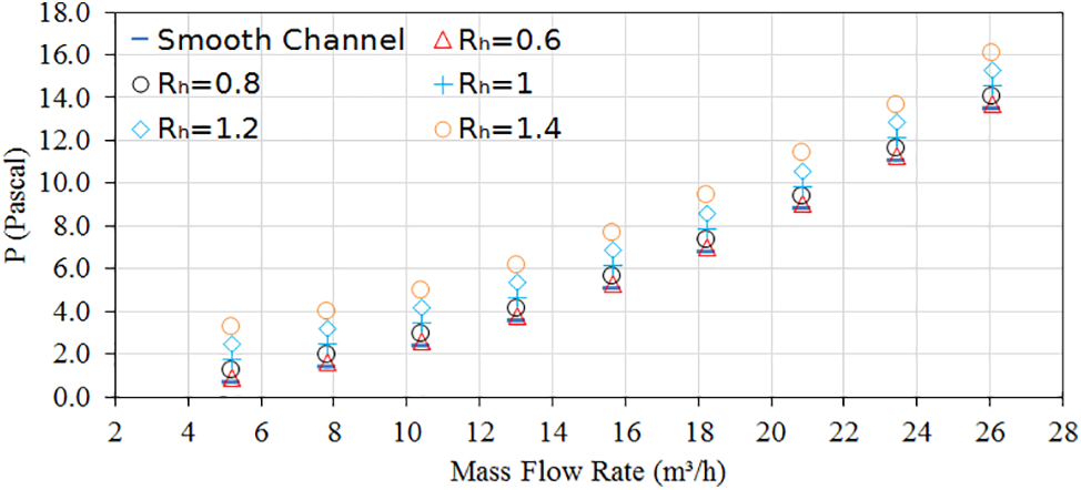
Figure 9: Variations of pressure drop with respect to volume flow rate for the plain collector and the collector with different height ratios of Rh = 0.6, 0.8, 1.0, 1.2, and 1.4
The influence of FDWVG with five height ratios; Rh = 0.6, 0.8, 1.0, 1.2, and 1.4, on the friction factor vs. volume flow rate in the collector is displayed in Fig. 10. All cases show that a decline in friction factor is accompanied by an increase in flow rate.
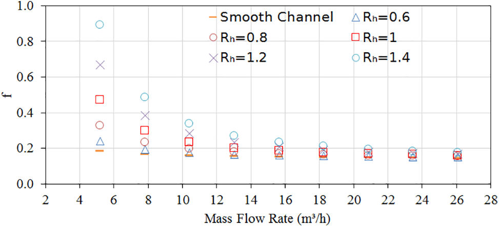
Figure 10: Variation of friction factor vs. volume flow rate for the plain collector and the collector with different height ratios of Rh = 0.6, 0.8, 1.0, 1.2 and 1.4
The friction factor of the collector with FDWVG is higher than the one with the smooth case. It is found that the friction factors achieved from the five height ratios have a similar tendency and lead to a decrease with a rise in mass flow rate and height ratio. In all the cases, the greatest values of the friction factor occurred at a lower mass flow rate.
The average growth of the friction factors in the roughened collector is about 8%, 18%, 30%, 43%, and 52% times higher than the smooth one with Rh = 0.6, 0.8, 1.0, 1.2, and 1.4, respectively. The collector with height ratio Rh = 1.4 yields the highest value of friction factor. The vortex generator with a bigger surface area produced a higher recirculation zone. Consequently, this can be attributed to the increased flow blockage, which leads to higher turbulence intensity, resulting in higher frictional coefficients [16,20].
Fig. 11 shows the influence of height ratios on energy efficiency with respect to the Reynolds number. The efficiency of energy increases with increasing Re and height ratio for all the cases. It is also observed that the FDWVG with Rh = 1.4 yields a higher energy of around 31.2%. It is implied that there is more energy absorption and less heat loss.
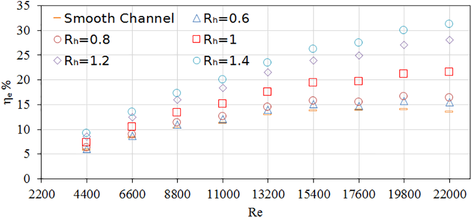
Figure 11: Variation of energy efficiency of the collector with respect to Reynolds number for the plain channel and the collector with different height ratios of Rh = 0.6, 0.8, 1.0, 1.2, and 1.4
The exergy efficiency of the collector vs. the Reynolds number is depicted in Fig. 12. As it can be observed, the maximum efficiency of exergy occurred at Re = 19800 for Rh = 1.4. The case of Rh = 1.2 is similar to the previous case (Rh = 1.4). While for the rest of cases (Rh = 0.6 − 1) including the smooth channel the maximum point enhancement occurs at Re = 15400. Similar to energy efficiency, the exergy efficiency increases with Re increasing for all the cases. It is also observed that the FDWVG with Rh = 1.4 yields a higher energy of around 37.3%.
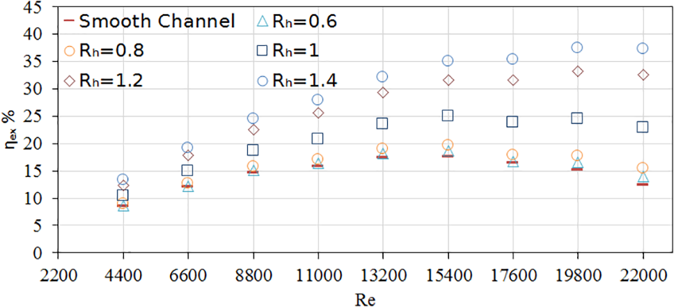
Figure 12: Variation of exergy efficiency of the collector with respect to Reynolds number for the plain channel and the collector with different height ratios of Rh = 0.6, 0.8, 1.0, 1.2, and 1.4
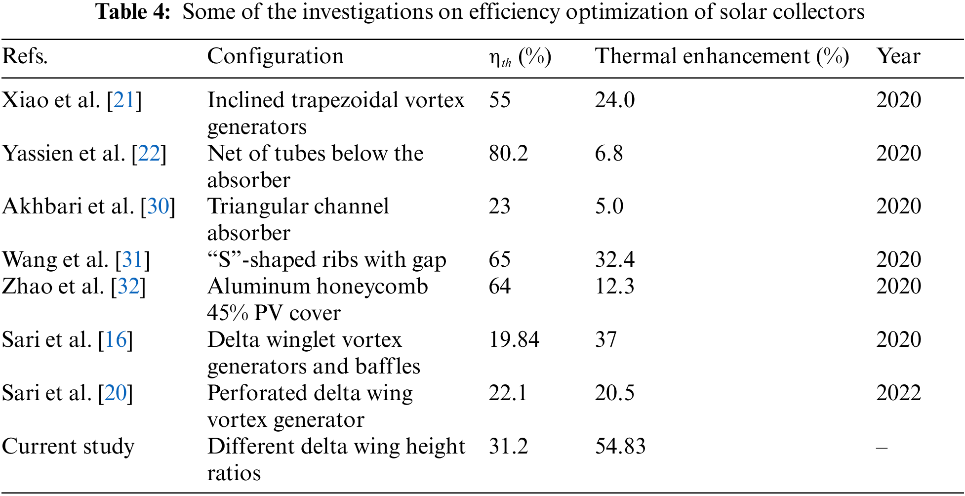
A summary of some of the very recent investigations on the efficiency optimization of solar collectors by using passive methods is presented in Table 4. As can be observed, the maximum efficiency augmentation in the current study is achieved compared to our recent studies [16,20].
To evaluate the heat transfer augmentation, the Overall Enhancement Ratio (OER) of the system at different Rh is analyzed in Fig. 13. It is observed that the OER increases with an increase of Re and Rh for all the cases. The overall enhancement ratio of the collector with different height ratios of Rh = 0.6, 0.8, 1.0, 1.2, and 1.4 are in the range of 0.90–1.01, 0.82–1.01, 0.77–1.10, 0.72–1.18 and 0.66–1.19, respectively. It was also discovered that; the cases of Rh larger than one, resulted in an overall enhancement ratio more than unity in the range of Reynalds numbers between 13200 and 22000.
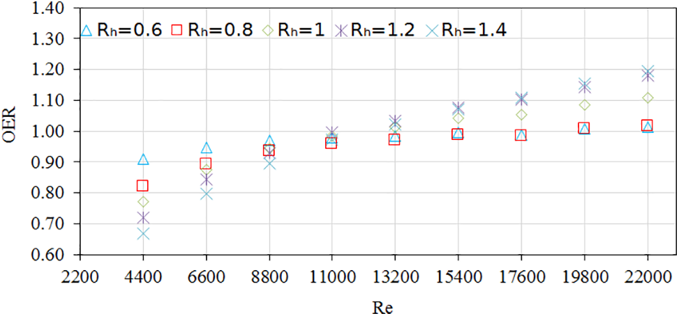
Figure 13: Comparison of OER at different Reynolds numbers
Solar Air Collectors (SACs) are widely used nowadays in residential, commercial, and industrial applications. Many attempts have been made to optimize them and enhance their efficiency. The studies have mainly targeted a constant vortex generator height ratio, and a gap existed for the effect of the vortex generator height ratio on the efficiency of SACs. Hence, in this paper, numerical and empirical investigations were conducted to examine the influence of the vortex generator height ratio on SAC implementation. The impacts of Rh on thermal performance, pressure drop, friction factor, energy, and exergy efficiencies, and overall enhancement ratio have been looked into.
The VGs with a height ratio of 1.4 exhibited superior performance compared to the other VGs with a lower height ratio in terms of heat-transfer rate, friction factor, and overal enhancement ratio. The results show that the overall enhancement ratio improved as the Rh of the VGs increased. It is also observed that the efficiency solar air collectors increased as the mass flow rates rose, and this led to a more effective heat transfer to the airflow.
It has been seen that the energy and exergy efficiencies increased with ascending Reynolds number and height ratio.
The numerical findings were validated using experimental data. The main results can be listed as follows:
a) The collector roughened with different height ratios of the vortex generators; Rh = 0.6, 0.8, 1, 1.2 and 1.4, supplies the average pressure drop greater than the smooth one by around 4%, 9%, 29%, 45%, and 50%, respectively.
b) The average growth of the friction factors in the roughened collector is about 8%, 18%, 30%, 43%, and 52% times higher than the smooth one with Rh = 0.6, 0.8, 1.0, 1.2, and 1.4, respectively.
c) Rh = 1.4 offers a significant enhancement in Nu number. The Friction factor and pressure drop increase with Rh.
d) At higher Re, the VGs with Rh = 1.4 yield higher energy and exergy efficiencies which indicates higher energy absorption and lower heat loss.
e) FDWVG with Rh = 1.4 yields higher energy and exergy performance to be around 31.2% and 37.3%, respectively.
f) The overall enhancement ratio for all the cases is above unity for Re number ranging from 13200 to 22000, and Rh = 1–1.4.
Acknowledgement: The authors thank Islamic Azad University–Shahrood Branch for their facilities and cooperation to perform this study.
Funding Statement: The authors received no specific funding for this study.
Author Contributions: The authors confirm contribution to the paper as follows: study conception and design: Ghobad Shafiei Sabet, Ahmad Fakhari; data collection: Ali Sari, Seyed Mehran Hoseini; analysis and interpretation of results: Ghobad Shafiei Sabet, Ahmad Fakhari, Nasrin Afsarimanesh; draft manuscript preparation, English correction and grammatical revision: Dominic Organ. All authors reviewed the results and approved the final version of the manuscript.
Availability of Data and Materials: The data and materials utilized in our research manuscript are accessible upon request from corresponding author, Ghobad Shafiei Sabet. Unreleased data is not available owing to confidentiality agreements with participants or constraints imposed by the data provider. We are dedicated to ensuring transparency and reproducibility in our research endeavors and will exert utmost diligence in granting access to the data, while adhering to ethical and regulatory limitations.
Conflicts of Interest: The authors declare that they have no conflicts of interest to report regarding the present study.
References
1. Han, F., Chen, C., Mahkamov, K., Wei, S., Ma, X. et al. (2020). Numerical and experimental study of laboratory and full-scale prototypes of the novel solar multi-surface air collector with double-receiver tubes integrated into a greenhouse heating system. Solar Energy, 202, 86–103. https://doi.org/10.1016/j.solener.2020.03.063 [Google Scholar] [CrossRef]
2. Fiuk, J., Dutkowski, K. (2019). Experimental investigations on thermal efficiency of a prototype passive SAC with wavelike baffles. Solar Energy, 188, 495–506. https://doi.org/10.1016/j.solener.2019.06.030 [Google Scholar] [CrossRef]
3. Phu, N. M., Bao, T. T., Hung, H. N., Tu, N. T., Hap, N. V. (2021). Analytical predictions of exergoeconomic performance of a solar air heater with surface roughness of metal waste. Journal of Thermal Analysis and Calorimetry, 144, 1727–1740. https://doi.org/10.1007/s10973-020-09787-5 [Google Scholar] [CrossRef]
4. Chen, Z. D., Bandopadhayay, P., Halldorsson, J., Byrjalsen, C., Heiselberg, P. et al. (2003). An experimental investigation of a solar chimney model with uniform wall heat flux. Building and Environment, 38(7), 893–906. https://doi.org/10.1016/S0360-1323(03)00057-X [Google Scholar] [CrossRef]
5. Afriyie, J. K., Nazha, M. A. A., Rajakaruna, H., Forson, F. K. (2009). Experimental investigations of a chimney-dependent solar crop dryer. Renewable Energy, 34(1), 217–222. https://doi.org/10.1016/j.renene.2008.04.010 [Google Scholar] [CrossRef]
6. Fudholi, A., Sopian, K., Ruslan, M. H., Alghoul, M. A., Sulaiman, M. Y. (2010). Review of solar dryers for agricultural and marine products. Renewable and Sustainable Energy Reviews, 14(1), 1–30. https://doi.org/10.1016/j.rser.2009.07.032 [Google Scholar] [CrossRef]
7. Bouadila, S., Kooli, S., Lazaar, M., Skouri, S., Farhat, A. (2013). Performance of a new solar air heater with packed-bed latent storage energy for nocturnal use. Applied Energy, 110, 267–275. https://doi.org/10.1016/j.apenergy.2013.04.062 [Google Scholar] [CrossRef]
8. Tuncer, A. D., Sözen, A., Khanlari, A., Amini, A., Şirin, C. (2020). Thermal performance analysis of a quadruple-pass solar air collector assisted pilot-scale greenhouse dryer. Solar Energy, 203, 304–316. https://doi.org/10.1016/j.solener.2020.04.030 [Google Scholar] [CrossRef]
9. Xianli, L., Zheng, S., Tian, G., Zhang, L., Yao, W. (2020). A new energy saving ventilation system assisted by transpired solar air collectors for primary and secondary school classrooms in winter. Building and Environment, 117, 106895. [Google Scholar]
10. Choi, Y., Takase, K., Mae, M. (2018). System performance of a residential building using the air-based solar heating system. Solar Energy, 171, 47–63. https://doi.org/10.1016/j.solener.2018.06.009 [Google Scholar] [CrossRef]
11. Yu, T., Liu, B., Lei, B., Yuan, Y., Bi, H. et al. (2019). Thermal performance of a heating system combining solar air collector with hollowventilated interior wall in residential buildings on Tibetan Plateau. Energy, 182, 93–109. https://doi.org/10.1016/j.energy.2019.06.047 [Google Scholar] [CrossRef]
12. Aman, S., Singh, R., Bhushan, B. (2018). Heat transfer and friction characteristics of solar air heater duct having protruded roughness geometry on absorber plate. Experimental Heat Transfer, 31, 571–585. https://doi.org/10.1080/08916152.2018.1468832 [Google Scholar] [CrossRef]
13. Žukauskas, A. (1994). Enhancement of forced convection heat transfer in viscous fluid flows. International Journal of Heat and Mass Transfer, 37, 207–212. https://doi.org/10.1016/0017-9310(94)90022-1 [Google Scholar] [CrossRef]
14. Dezan, D. J., Rocha, A. D., Ferreira, W. G. (2020). Parametric sensitivity analysis and optimisation of a solar air heater with multiple rows of longitudinal vortex generators. Applied Energy, 263, 114556. https://doi.org/10.1016/j.apenergy.2020.114556 [Google Scholar] [CrossRef]
15. Abdullah, A. S., Al-Sood, M. M. A., Omara, Z. M., Bek, M. A., Kabeel, A. E. (2018). Performance evaluation of a new counter flow double pass solar air heater with turbulators. Solar Energy, 173, 398–406. https://doi.org/10.1016/j.solener.2018.07.073 [Google Scholar] [CrossRef]
16. Sari, A., Sadi, M., Sabet, G. S., Mohammadiun, M., Mohammadiun, H. (2020). Experimental analysis and exergetic assessment of the solar air collector with delta winglet vortex generators and baffles. Journal of Thermal Analysis and Calorimetry, 145, 867–885. [Google Scholar]
17. Karim, M. A., Hawlader, M. N. A. (2006). Performance evaluation of a v-groove solar air collector for drying applications. Applied Thermal Engineering, 26(1), 121–130. https://doi.org/10.1016/j.applthermaleng.2005.03.017 [Google Scholar] [CrossRef]
18. Zhu, T., Diao, Y., Zhao, Y., Ma, C. (2017). Performance evaluation of a novel flat-plate solar air collector with micro-heat pipe arrays (MHPA). Applied Thermal Engineering, 118, 1–16. https://doi.org/10.1016/j.applthermaleng.2017.02.076 [Google Scholar] [CrossRef]
19. Agathokleous, R., Barone, G., Buonomano, A., Forzano, C., Kalogirou, S. A. et al. (2019). Building façade integrated solar thermal collectors for air heating: Experimentation, modelling and applications. Applied Energy, 239, 658–679. https://doi.org/10.1016/j.apenergy.2019.01.020 [Google Scholar] [CrossRef]
20. Sari, A., Sadi, M., Sabet, G. S., Mohammadiun, M., Mohammadiun, H. (2022). Experimental and numerical investigation of implementing a novel vortex generator: A perforated delta wing vortex generator (PDWVG) on the performance of solar air collector. Iranian Journal of Chemistry and Chemical Engineering, 41(119), 3168–3180. [Google Scholar]
21. Xiao, H., Dong, Z., Liu, Z., Liu, W. (2020). Heat transfer performance and flow characteristics of solar air heaters with inclined trapezoidal vortex generators. Applied Thermal Engineering, 179, 115484. https://doi.org/10.1016/j.applthermaleng.2020.115484 [Google Scholar] [CrossRef]
22. Yassien, H. N. S., Alomar, O. R., Salih, M. M. M. (2020). Performance analysis of triple-pass solar air heater system: Effects of adding a net of tubes below absorber surface. Solar Energy, 207, 813–824. https://doi.org/10.1016/j.solener.2020.07.041 [Google Scholar] [CrossRef]
23. Akpinar, E. K., Koçyiğit, F. (2010). Energy and exergy analysis of a new flat-plate solar air heater having different obstacles on absorber plates. Applied Energy, 87(11), 3438–3450. https://doi.org/10.1016/j.apenergy.2010.05.017 [Google Scholar] [CrossRef]
24. Petela, R. (2003). Exergy of undiluted thermal radiation. Solar Energy, 74, 469–488. https://doi.org/10.1016/S0038-092X(03)00226-3 [Google Scholar] [CrossRef]
25. Shih, T. H., Liou, W. W., Shabbir, A., Yang, Z., Zhu, J. A. (1995). New k–ϵ eddy viscosity model for high Reynolds number turbulent flows. Computational Fluids, 24, 227–238. [Google Scholar]
26. Fakhari, A. (2015). Wall-layer modelling of massive separation in large eddy simulation of coastal flows (Ph.D. Thesis). University of Trieste, Trieste, Italy. [Google Scholar]
27. Fakhari, A., Cintolesi, C., Petronio, A., Roman, F., Armenio, V. (2018). Numerical simulation of hot smoke plumes from funnels. In: Technology and science for the ships of the future, pp. 238–245. IOS Press. [Google Scholar]
28. Fakhari, A. (2019). A new wall model for large eddy simulation of separated flows. Fluids, 4, 197. 2019. https://doi.org/10.3390/fluids4040197 [Google Scholar] [CrossRef]
29. Skullong, S., Peomvonge, P., Thianpong, C., Jayranaiwachira, N. (2017). Thermal behaviors in a round tube equipped with quadruple perforated-delta-winglet pairs. Applied Thermal Engineering, 115, 229–243. https://doi.org/10.1016/j.applthermaleng.2016.12.082 [Google Scholar] [CrossRef]
30. Akhbari, M., Rahimi, A., Hatamipour, M. S. (2020). Modeling and experimental study of a triangular channel solar air heater. Applied Thermal Engineering, 170, 114902. https://doi.org/10.1016/j.applthermaleng.2020.114902 [Google Scholar] [CrossRef]
31. Wang, D., Liu, J., Liu, Y., Wang, Y., Li, B. et al. (2020). Evaluation of the performance of an improved solar air heater with “S” shaped ribs with gap. Solar Energy, 195, 89–101. https://doi.org/10.1016/j.solener.2019.11.034 [Google Scholar] [CrossRef]
32. Zhao, Y., Meng, T., Jing, C., Hu, J., Qian, S. (2020). Experimental and numerical investigation on thermal performance of PV-driven aluminium honeycomb solar air collector. Solar Energy, 204, 294–306. https://doi.org/10.1016/j.solener.2020.04.047 [Google Scholar] [CrossRef]
Cite This Article
 Copyright © 2024 The Author(s). Published by Tech Science Press.
This work is licensed under a Creative Commons Attribution 4.0 International License , which permits unrestricted use, distribution, and reproduction in any medium, provided the original work is properly cited.
 Downloads
 Citation Tools