
 Submit a Paper
 Propose a Special lssue
 Open Access
ARTICLE
Effect of Heatpipe Array Condenser Section Length on Thermal Cooling of Li-Ion Batteries
1 Department of Mechanical Engineering, University of Alaska Fairbanks, Fairbanks, 99775, USA
2 Department of Mechanical Engineering, University of Ibadan, Ibadan, 200005, Nigeria
* Corresponding Authors: Olanrewaju M. Oyewola. Email: ,
Frontiers in Heat and Mass Transfer 2024, 22(2), 475-490. https://doi.org/10.32604/fhmt.2024.047714
Received 15 November 2023; Accepted 14 February 2024; Issue published 20 May 2024
 View Full Text
 Download PDF
Abstract
One of the new methods for ensuring that the battery in a thermal energy storage system is kept at the proper temperature is the heat pipe-based Thermal Management System (TMS). In this study, the improvement of cooling performance of a heat pipe based TMS is examined through the variation of condenser section length of heat pipes in an array. The TMSs with an array of heat pipes with different condenser section lengths are considered. The system performances are evaluated using a validated numerical method. The results show that a heat pipe-based TMS provides the best cooling performance when a wavy-like variation is employed and when the condenser section length of the last set of the heat pipe in the array is greater than that of the penultimate set. The maximum cell temperature and the maximum temperature difference within the cell of this TMS are decreased by 4.2 K and 1.1 K, respectively, when compared to the typical heat pipe based TMS with zero variation in its condenser section length. Conclusively, the strategy offers an improvement in the thermal uniformity for all the TMS cases.Keywords
Nomenclature
| Q | Generated heat |
| Battery thermal conductivity | |
| Heat pipe and radiator thermal conductivity | |
| Battery specific heat capacity | |
| Heat pipe and radiator specific heat capacity | |
| Battery density | |
| Heat pipe and radiator density | |
| T | Temperature |
| Average pressure at the inlet | |
| Average pressure at the outlet | |
| Inlet air flow rate |
With the prevailing climate change and current energy crisis, the implementation of lithium-ion (Li-ion) batteries as a significant power source in the transportation and energy industry (specifically solar energy storage) has grown rapidly in recent decades. Consequently, the benefit of high energy density, excellent recyclability, low self-discharge rate, and lightweight offered by Li-ion batteries have encouraged their usage as a power source [1]. Li-ion batteries have facilitated the emergence of electric vehicles (EVs) in the transportation industry. The use of these batteries in EVs has provided an alternative route in the effort to reduce our reliance on fossil fuels, which could significantly reduce greenhouse gas emissions. This is particularly crucial in the face of the escalating climate change crisis. In the energy industry, Li-ion batteries have found extensive application in the storage of renewable energy sources such as solar and wind. The intermittent nature of these power sources necessitates efficient storage solutions, and Li-ion batteries have proven to be highly effective in this regard. They enable the storage of excess energy produced during high supplies, which can then be used during periods of low energy sources or high demand. Notably, the extensive utilization of Li-ion batteries also causes battery disposal due to their lifespan, causing environmental pollution. It is imperative to address the problem by providing measures to extend the battery service life thereby ensuring Li-ion batteries’ sustainable usage. High temperature is a great adversary to the performance of Li-ion batteries, resulting from a large amount of heat produced during the charge and discharge processes [2,3], leading to an increase in battery temperature and temperature inhomogeneity. Various studies have shown that high temperature and temperature inhomogeneity affect the battery storage capacity and lifespan [3–5]. Thus, the introduction of a thermal management system is crucial in ensuring Li-ion battery packs operate within an optimum range of 15°C–45°C and with a temperature difference below 5°C [2,6–8], which are necessary to ensure a balance between the battery performance and service life [8,9].
There are currently three primary categories of thermal management systems: air cooling, liquid cooling, and phase-change material cooling. These categories are based on cooling strategies due to the heat-transfer approach they offer. The advantages of the air-cooling system, such as its simple design, lightweight, and cheap cost, make it widely used. However, air’s low specific heat capacity could lead to poor temperature uniformity in a battery pack. As a result, numerous studies have been conducted to enhance the thermal performance of the air-cooling system through control strategy, structure design, and battery arrangement [10–15]. Due to the significantly higher heat transfer coefficient of liquid coolant, liquid cooling is a more efficient cooling system than air. The design of the flow channel and the coolant’s thermal characteristics have been the subject of various research [16–18]. Employing liquid as a coolant increases the risk of short circuits and leakage, and the system becomes more expensive when pumps are involved. Additionally, increased energy usage is observed as a result of high pressure drop across the liquid cooling system [3,19]. Phase change materials (PCMs) are extremely beneficial for a range of heat transfer applications due to their mix of sensible and latent heat capacities [20–23]. However, there are substantial limitations such as limited thermal conductivities, high cost and slow rates of thermal stability [24,25], additionally, PCMs are non-recyclable and can only provide passive heat absorption.
A thermal management system based on heat pipe employed to cool Li-ion batteries is a relatively new strategy [8,26]. Heat pipes are known to exhibit very high thermal conductivity with several benefits, including affordability, effectiveness, compact structure, long lifespan, and excellent heat transfer performance [27]. Zhang et al. [6] conducted a numerical comparison of three battery temperature profiles in a TMS using flat heat pipes, natural convection of air, and aluminum plate cooling. They observed that implementing the flat heat pipes could effectively reduce the maximum temperature and improve temperature uniformity with the least amount of energy usage. Greco et al. [28] developed a validated one-dimensional numerical model of a heat pipe sandwiched between prismatic Li-ion cells utilizing a thermal circuit technique and compared the performance of the heat pipe cooling to that of a forced convection cooling, they observed about 54% cooling performance with regard to the maximum temperature when using a heat pipe. Ye et al. [29] investigated the thermal performance of the heat pipe based TMS under a steady state and transient situation during fast charging events. The temperature uniformity is found to be enhanced by a cylinder vortex generator positioned beside the heat pipe condensers. They also observed that the TMS performed significantly better due to the inclusion of copper heat spreaders and radiators. Ye et al. [30] experimentally evaluated battery temperatures with and without micro heat pipe arrays, demonstrating the importance of heat pipes in reducing the temperature increase of a battery pack at a discharge rate of 1C and improving the temperature uniformity of the pack during operation. Zhang et al. [31] proposed a flat heat pipe and wet cooling TMS where its numerical model was created and compared to the conventional air cooling under a 1C–3C discharge rate. They observed that there was an improvement in the maximum temperature during the three discharge rates, but the temperature uniformity deteriorated due to the low inlet temperature regarding the wet cooling involvement. They suggested the use of air cooling with wet cooling to improve temperature uniformity. Tran et al. [32] experimented on a flat heat pipe TMS and a traditional heat sink in various inclined positions. They discovered that heat pipes can decrease thermal resistance while also maintaining the batteries at an appropriate temperature. Kim et al. [33] designed a heat generation model using Simulink and MATLAB to predict battery pack power and compare the effectiveness of heat pipe specifications. They integrated and validated this model with system-level thermal modeling and validated it with numerical and experimental data. The study found that heat pipes can reduce the temperature difference between the battery cell and the ambient environment to less than three degrees in high power output scenarios. Smith et al. [34] introduced a new way to manage the temperature of high-power batteries with eight prismatic cells that can handle heat loads up to 400 W. The system uses heat pipes to cool the cells and then transports the heat through remote heat transfer pipes to liquid-cooled cold plates located 300 mm away. This method provides better temperature consistency and makes for a safer system than traditional liquid-cooled systems. The system can handle a 50 W heat load from each cell while keeping its temperature below 55°C by using a water coolant with a 25°C inlet temperature and a flow rate of 1 liter/min.
As previously stated, heat pipes have more thermal conductivities than air, liquid, and PCM, resulting in improved cooling capabilities and making them better equipped for cooling large-scale battery packs, particularly at high discharge rates. A heat pipe is grouped into three sections: evaporator, adiabatic, and condenser. The evaporator is responsible for the transfer of heat from the heat source into the heat pipe, while the condenser is responsible for dissipating the heat from the heat pipe to the outside surroundings. Recent studies on heat pipes have focused on flat heat pipes as a result of the wider contact area they cover when compared to tubular heat pipes, However, studies have been limited in research on tubular heat pipes array which also offers substantial contact area over the heat source but none have studied the influence of condenser section length of tubular heat pipes array on the cooling capability of a TMS. In this study, a TMS using air cooling and a tubular heat pipe array was investigated, and a three-dimensional model was developed using the numerical method where the cooling performance is based on the maximum temperature and temperature uniformity in the battery cell and power consumption by the TMS. Investigations were conducted on how varying condenser lengths of heat pipes in an array influence the battery temperature profile. Furthermore, the thermal performances of case models were examined under increasing inlet air flow rate, temperature, and thermal conductivity of heat pipe. The proposed method in this study will offer insight on the basis of implementation for a tubular heat pipe array of different condenser section lengths in a heat pipe based TMS to aid in lowering the maximum temperature of the cell, improving cell temperature uniformity, and reducing system power consumption.
The physical geometry of the TMS [8] is depicted in Fig. 1. An array of sixteen tubular heat pipes sandwiched between two Li-ion battery cells to ensure contact with both surfaces of each cell, the spacing between the cells was 3 mm. A radiator of twelve cooling fins was placed at the condenser section of the heat pipe array for better heat spread.
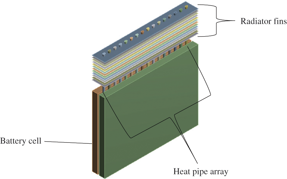
Figure 1: The thermal management system (TMS)
Table 1 lists the specifications of the heat pipes, radiator, and battery cells. During operation, the evaporator section of the heat pipe takes in the heat generated by the battery cell through conduction, where phase change is to occur to the working fluid in the heat pipe from which the heat energy is transmitted to the condenser section, where it is being dissipated out by the aid of the radiator and the circulating air through convection. This study did not simulate the phase change process within the heat pipe. The heat pipe was tested for thermal conductivity in a previous study [8], and it was discovered to exhibit thermal conductivity between 1100 W/m.K at an inlet air temperature of 9°C. As a result, the thermal conductivity of the heat pipe and the inlet air temperature was set to 1100 W/m.K and 9°C respectively in the current numerical study. The heat pipe diameter was initially 4 mm more than the gap between the cells. To accommodate that, the heat pipe was pre-pressed to form an elliptical deformation with a major axis and minor axis of 5 and 3 mm, respectively. The length of the evaporator and adiabatic section are 150 and 20 mm, respectively, while the condenser length was initially set at 50 mm for validation purposes. In this study, different cases of arrays based on various condenser section length arrangements were numerically investigated to observe their cooling performance on the battery cells. Table 2 displays the length arrangement of the condenser section of each array case. For the array cases, the heat pipes are grouped into four sets (three heat pipes per set), from which each set is assigned a condenser section length different from or similar to that of other sets.
The highest temperature and temperature difference on the cell’s surface in contact with the heat pipe array, as well as the power consumption of the TMS, were measured in this study as an indicator of cooling performance. A 3-dimensional CFD analysis was carried out to determine the flow and temperature profile occurrence in the TMS. Considering the channel for the cooling air, a hydraulic diameter of a rectangular channel was used to determine the flow regime. The system was assumed to have a turbulent flow regime since the Reynolds number for the inlet flow rate of 3 l/s [8] is much higher than 5500. To simulate the circulating airflow in the TMS, the Reynolds Averaged Navier-Stokes equation and the realizable k - ε turbulence model are utilized, while the energy conservation equations [35] (1)–(2) are the governing equations used for the battery cells, heat pipes, and radiator.
For the boundary conditions (Fig. 2), the system’s inlet was set to a velocity-inlet boundary condition based on a flow rate of 3 l/s at a constant temperature of 9°C, while the outlet was set to pressure-outlet boundary condition with surrounding air-conditioned to atmospheric pressure. The condenser section and the radiator surfaces were set to a no-slip condition, while an adiabatic wall was placed to the surrounding wall of the battery cell and adiabatic sections of the heat pipe array. Finally, a coupled wall was assigned to the contact regions between the condenser sections and air medium, condenser sections and radiator, battery, and evaporator sections of the heat-pipe array.
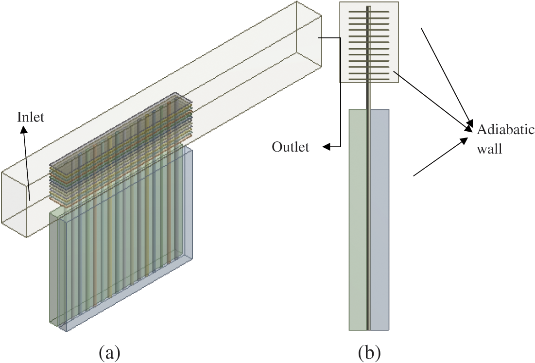
Figure 2: Computational domain showing boundary conditions: (a) Orthogonal view and (b) Side view
The numerical modelling used the following assumptions:
• Heat transfer from radiation is ignored.
• Thermal contact resistances at the interfaces are disregarded.
• Batteries and air have consistent physical properties.
• The environment’s temperature and pressure are both constant.
• With a constant rate of heat generation of 7.5 W, the battery cell is considered a constant heat source.
Additionally, when solving the governing equations, the solver (ANSYS 19 R1) took into account the SIMPLE approach. Employing central-differencing and second-order terms, the convective and diffusive terms were discretized. For the flow and energy terms, the convergence conditions for the iteration residuals were set at 10−4 and 10−8, respectively.
To guarantee a solution-independent grid, a grid sensitivity study was carried out by keeping a constant sizing in the structural grid on the battery cells, heat pipes, and radiator while varying the element sizing in the unstructured grid of the fluid (air) medium. To evaluate the sensitivity of the grid, the minimum temperature (Tmin) and maximum temperature (Tmax) of the battery cell were used as variables. The stability of these variables as the grid number rises is shown in Fig. 3. It was shown that once the grid number exceeds 810,881, the change in Tmax and Tmin becomes stable with variations smaller than 0.03 K and 0.02 K, respectively. For this study, a model with a grid size of 810,881 was chosen and used. The selected grid is shown in Fig. 4.
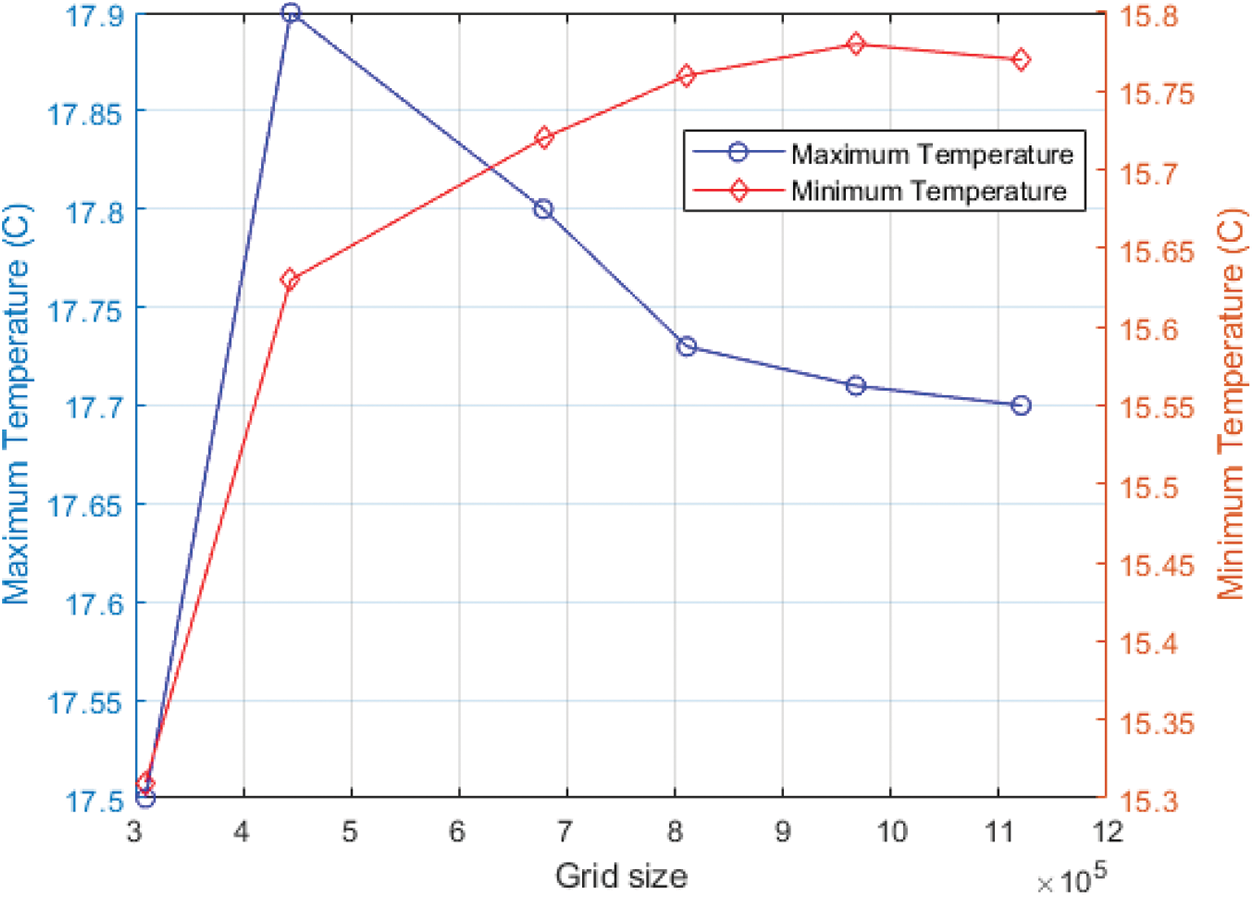
Figure 3: Mesh convergence analysis
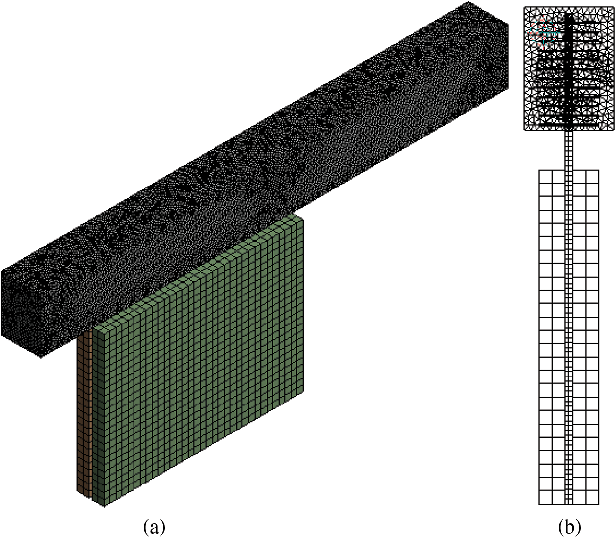
Figure 4: Selected grid size (a) Orthogonal view and (b) Side view
2.2.3 Validation of the Numerical Model
The findings from this work were compared with those from a previous experimental study to evaluate the validity of the model. Simulations were run with settings that matched those of the experiment; Fig. 5 shows the Tmax and Tmin of the present study and experimental data by Belyaev et al. [8]. The results of the current work and previous study show a very high degree of agreement. This study’s numerical model was shown to have an acceptable error of less than 3.0% for the Tmax and 4.5% for the Tmin. This demonstrates the validity and viability of the model.
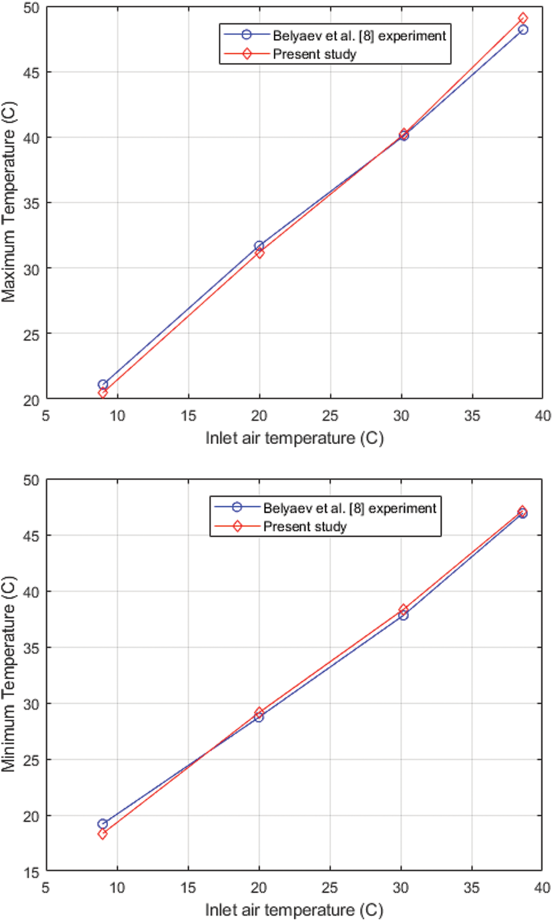
Figure 5: Comparison between experimental [5] and present simulation results
The temperature profile of both battery cells is similar as the heat pipes are sandwiched between the two cells, maintaining similar contact positions on the cells, thereby performing equal heat extraction at similar positions of the opposing cells. The cooling abilities of several TMS cases (Table 2) were assessed and compared. Each case was simulated, and their numerical result was evaluated and summarized in Table 3. Their cooling abilities were calculated using three variable indices in terms of the cell’s maximum temperature (Tmax), maximum temperature difference within the cell (
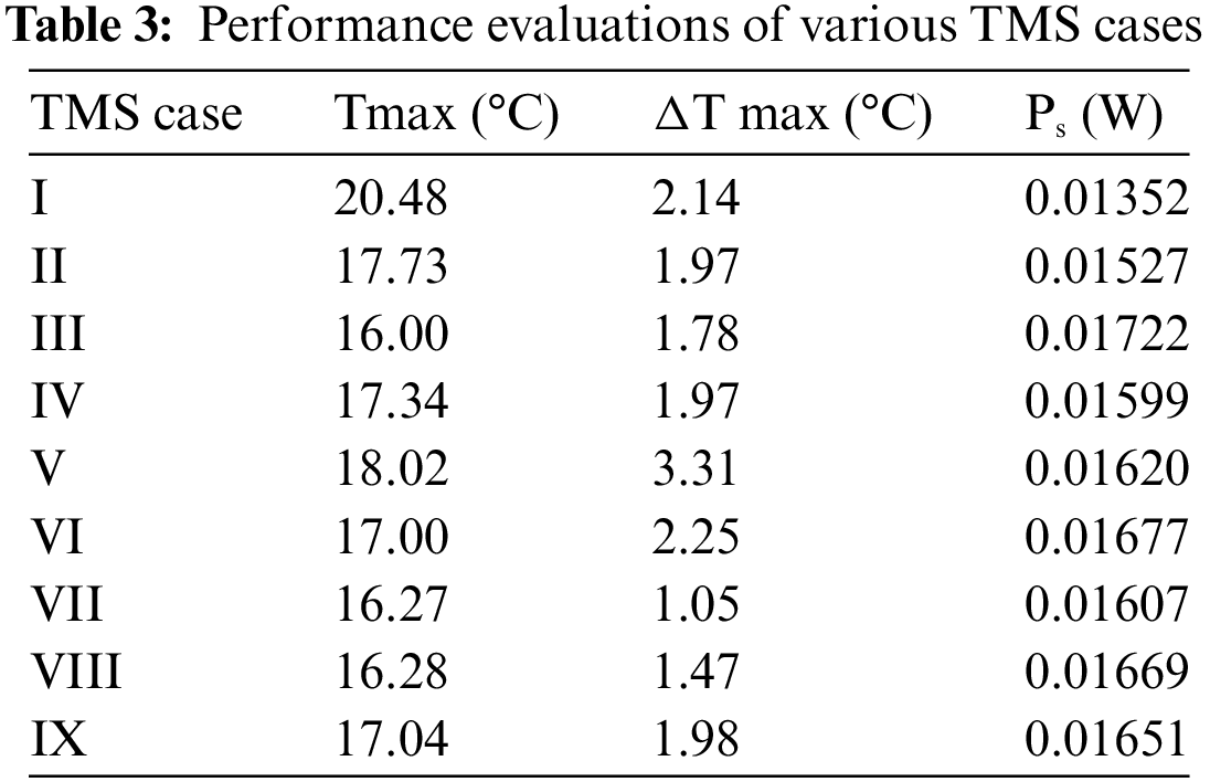
In this analysis, the cases will be grouped into three categories based on the condenser section length of the heat pipe array: zero variation, step-like variation, and wavy-like variation. Cases I, II, and III are the TMS with heat pipe array of constant length (i.e., zero variation arrangement). As seen in Table 3, the Tmax and
Regarding cases IV and V, where a step-like variation in the condenser section length was introduced, it can be seen in Table 3 that case IV performs better than case V in terms of its thermal performance and power consumption. Case IV offers 0.68°C and 1.34°C lower in its Tmax and
Cases VI, VII, VIII, and IX are the systems with a wavy-like variation in the length of the condenser section of the heat pipe array. Similarly, it can be seen from Table 3 that case VII performs best among this system’s category across all performance indices.
Furthermore, Tmax,
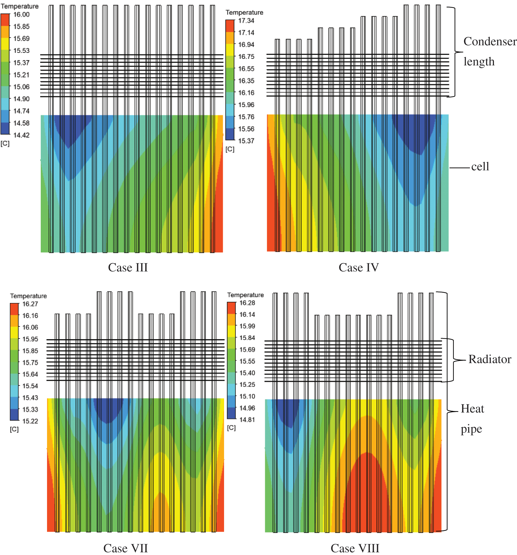
Figure 6: Battery temperature profiles of various TMS cases
The cooling performance of TMS cases, such as cases III, IV, VII, and VIII, was further examined by varying inlet air velocities and temperatures. Fig. 7a displays the maximum temperature of the cell for each case under various inlet air velocities at an inlet temperature of 9°C. Unsurprisingly, all the cases experienced a drop in maximum cell temperature as the inlet air velocity increased since more heat was extracted from the system. As a result of offering the longest condenser section of equal length, case III offers the lowest maximum temperature, followed by cases VII and VIII, since its condenser provides more avenues for convective heat transfer out of the system. However, case VII maintained more thermal uniformity under the studied flow rates than other cases. From Fig. 7b, the thermal uniformity of case III improves steadily as the inlet velocity increases while that of Case VII drops slowly, it still performs better than case III. However, a further increase in the inlet flow rate should cause case III to outperform case VIII but at the expense of higher power consumption. To observe the cooling performance of the TMS cases under hotter conditions, the analysis was conducted under various inlet air temperatures at an inlet air flow rate of 3 l/s, as shown in Fig. 8. The thermal conductivity of the heat pipe increases as the surrounding temperature increases [8]; in the current work, the thermal conductivity of the heat pipe under different inlet air temperatures was considered based on the study of Belyaev et al. [8] and the thermophysical properties of air under each temperature were considered. From Fig. 8a, case III still performs best in terms of the lowest maximum cell temperature it offers. However, it can be observed that increasing the thermal conductivity of the heat pipe in a TMS by raising the inlet air temperature can be counterproductive, as the maximum cell temperature for all cases increases, which could be problematic for battery longevity. Fig. 8b shows the thermal uniformity of different TMS cases under various inlet air temperatures, there is an improvement in the thermal uniformity for most cases as their maximum temperature differences slowly drop with increasing inlet air temperature, this suggests that the increased thermal conductivity of a heat pipe array can improve the thermal uniformity of cells in a TMS.
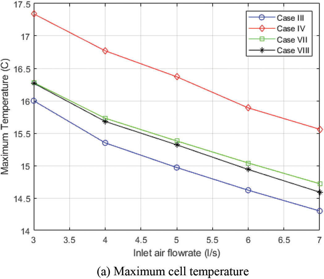
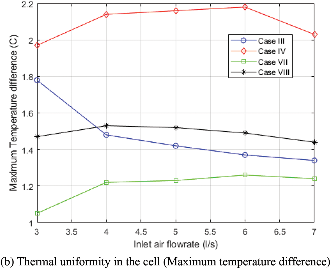
Figure 7: Comparison of the numerical results of various TMSs at different inlet flowrate
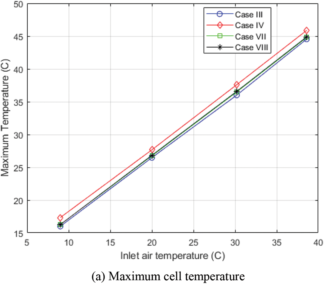
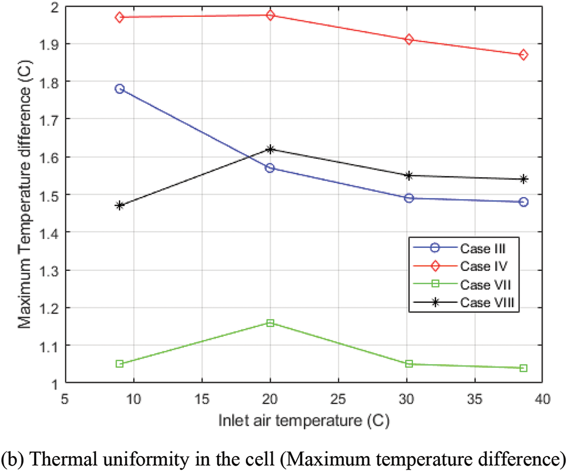
Figure 8: Comparison of the numerical results of various TMSs at different inlet air temperatures
From the above analysis, the step-like variation (case IV) performs poorly, while both the zero variation (case III) and wave-like variation (case VII) perform better in Tmax and
In this study, the condenser section length of heat pipes in an array was varied to improve the cooling efficiency of the battery TMS. The CFD approach is used to determine the temperature field and power consumption of the TMS. Experimental data were used to validate the accuracy of the current numerical method. Different variations in condenser section length of heat pipes in an array were created based on three arrangements: zero variation, step-like variation, and wavy-like variation. The numerical approach is used to evaluate and compare the performances of different TMS cases. The study concluded that the thermal efficiency of TMS cooled by a heat pipe array is significantly impacted by the variation in the condenser section length of heat pipes in an array. The TMS (denoted as cases VII and VIII) provides great cooling performance when a wavy-like variation is employed and when the condenser section length of the last set of heat pipes in an array is greater than that of the penultimate set. It is suggested that the heat transfer rate is enhanced over the step and wavy-like variations than zero variations. The results of the numerical study demonstrate that in comparison to the typical TMS with zero variation in condenser section length (case I), the maximum cell temperature and the maximum temperature difference within a cell of case VII are decreased by 4.2 K and 1.1 K, respectively. Although case III provides the lowest maximum cell temperature, it will require more energy to outperform case VII in terms of thermal uniformity. Increasing the inlet air temperature to raise the thermal conductivity of the heat pipe of the TMS does not lower the maximum cell temperature of the systems; nevertheless, there is an improvement in the thermal uniformity of all the TMS cases.
Future research may be explored considering the current study as regards the influence of unsteady air flow, different patterns of arrangement, and/or longer condenser section length on the thermal cooling of these batteries.
Acknowledgement: None.
Funding Statement: The authors received no specific funding for this study.
Author Contributions: The authors confirm contribution to the paper as follows: study conception and design: Olanrewaju. M. Oyewola; data collection: Olanrewaju M. Oyewola, Adetokunbo A. Awonusi, Olawale S. Ismail; analysis and interpretation of results: Olanrewaju M. Oyewola, Adetokunbo A. Awonusi, Olawale S. Ismail; draft manuscript preparation: Olanrewaju M. Oyewola, Adetokunbo A. Awonusi, Olawale S. Ismail. All authors reviewed the results and approved the final version of the manuscript.
Availability of Data and Materials: The data are available from the corresponding author upon request.
Conflicts of Interest: The authors declare that they have no conflicts of interest to report regarding the present study.
References
1. Wang, L., Zhao, Y., Quan, Z., Liang, J. (2021). Investigation of thermal management of lithium-ion battery based on micro heat pipe array. Journal of Energy Storage, 39, 102624. https://doi.org/10.1016/j.est.2021.102624 [Google Scholar] [CrossRef]
2. Behi, H., Behi, M., Karimi, D., Jaguemont, J., Ghanbarpour, M. et al. (2020). Heat pipe air-cooled thermal management system for lithium-ion batteries: High power applications. Applied Thermal Engineering, 116240. https://doi.org/10.1016/j.applthermaleng.2020 [Google Scholar] [CrossRef]
3. Behi, H., Karimi, D., Behi, M., Jaguemont, J., Ghanbarpour, M. et al. (2020). Thermal management analysis using heat pipe in the high current discharging of lithium-ion battery in electric vehicles. Journal of Energy Storage, 32, 101893. https://doi.org/10.1016/j.est.2020.101893 [Google Scholar] [CrossRef]
4. Oyewola, O., Awonusi, A., Ismail, O. (2022). Performance improvement of air-cooled battery thermal management system using sink of different pin-fin shapes. Emerging Science Journal, 6(4), 851–865. https://doi.org/10.28991/ESJ-2022-06-04-013 [Google Scholar] [CrossRef]
5. Wang, Q., Jiang, B., Li, B., Yan, Y. (2016). A critical review of thermal management models and solutions of lithium-ion batteries for the development of pure electric vehicles. Renewable and Sustainable Energy Reviews, 64, 106–128. https://doi.org/10.1016/j.rser.2016.05.033 [Google Scholar] [CrossRef]
6. Zhang, Z., Wei, K. (2020). Experimental and numerical study of a passive thermal management system using flat heat pipes for lithium-ion batteries. Applied Thermal Engineering, 166, 114660. https://doi.org/10.1016/j.applthermaleng.2019 [Google Scholar] [CrossRef]
7. Saw, L. H., Ye, Y., Tay, A. A. O., Chong, W. T., Kuan, S. H. et al. (2016). Computational fluid dynamic and thermal analysis of lithium-ion battery pack with air cooling. Applied Energy, 177, 783–792. https://doi.org/10.1016/j.apenergy.2016.05.12 [Google Scholar] [CrossRef]
8. Belyaev, A., Rohatgi, U., Fedorchenko, D., Khazhmuradov, M., Lukhanin, A. et al. (2016). Investigation of heat pipe cooling of Li-ion batteries. First Thermal and Fluids Engineering Summer Conference, pp. 793–804. New York, USA. [Google Scholar]
9. Guo, Z., Xu, J., Xu, Z. (2020). Experimental and numerical study of flat heat pipe-liquid cooling battery thermal management system. International Conference on Applied Energy, pp. 1–4. Bangkok, Thailand. [Google Scholar]
10. Oyewola, O., Ismail, O., Awonusi, A. (2022). Examination of channel angles influence on the cooling performance of air-cooled thermal management system of Li-ion battery. International Review of Mechanical Engineering, 16(4), 172–179. https://doi.org/10.15866/ireme.v16i4.22239 [Google Scholar] [CrossRef]
11. Liu, K., Wang, Y., Zhang, J., Liu, Z. (2014). Shortcut computation for the thermal management of a large air-cooled battery pack. Applied Thermal Engineering, 66, 445–452. https://doi.org/10.1016/J.APPLTHERMALENG.2014.02.040 [Google Scholar] [CrossRef]
12. Chen, K., Wu, W., Yuan, F., Chen, L., Wang, S. (2019). Cooling efficiency improvement of air-cooled battery thermal management system through designing the flow pattern. Energy, 167, 781–790. https://doi.org/10.1016/J.ENERGY.2018.11.011 [Google Scholar] [CrossRef]
13. Li, X., He, F., Ma, L. (2013). Thermal management of cylindrical batteries investigated using wind tunnel testing and computational fluid dynamics simulation. Journal of Power Sources, 238, 395–402. https://doi.org/10.1016/J.JPOWSOUR.2013.04.073 [Google Scholar] [CrossRef]
14. Li, W., Xiao, M., Peng, X., Garg, A., Gao, L. (2019). A surrogate thermal modeling and parametric optimization of battery pack with air cooling for EVs. Applied Thermal Engineering, 147, 90–100. https://doi.org/10.1016/j.applthermaleng.2018.10.060 [Google Scholar] [CrossRef]
15. Erb, D. C., Kumar, S., Carlson, E., Ehrenberg, I. M., Sarma, S. E. (2017). Analytical methods for determining the effects of lithium-ion cell size in aligned air-cooled battery packs. Journal of Energy Storage, 10, 39–47. https://doi.org/10.1016/j.est.2016.12.003 [Google Scholar] [CrossRef]
16. Patil, M. S., Seo, J. H., Panchal, S., Jee, S. W., Lee, M. Y. (2020). Investigation on thermal performance of water-cooled Li-ion pouch cell and pack at high discharge rate with U-turn type microchannel cold plate. International Journal of Heat and Mass Transfer, 155, 119728. https://doi.org/10.1016/j.ijheatmasstransfer.2020.119728 [Google Scholar] [CrossRef]
17. Wu, F., Rao, Z. (2017). The lattice Boltzmann investigation of natural convection for nanofluid based battery thermal management. Applied Thermal Engineering, 115, 659–669. https://doi.org/10.1016/j.applthermaleng.2016.12.139 [Google Scholar] [CrossRef]
18. Qian, Z., Li, Y., Rao, Z. (2016). Thermal performance of lithium-ion battery thermal management system by using mini-channel cooling. Energy Conversion Management, 126, 622–631. https://doi.org/10.1016/J.ENCONMAN.2016.08.063 [Google Scholar] [CrossRef]
19. Liu, H., Wei, Z., He, W., Zhao, J. (2017). Thermal issues about Li-ion batteries and recent progress in battery thermal management systems: A review. Energy Conversion Management, 150, 304–330. https://doi.org/10.1016/J.ENCONMAN.2017.08.016 [Google Scholar] [CrossRef]
20. Javani, N., Dincer, I., Naterer, G. F., Yilbas, B. S. (2014). Heat transfer and thermal management with PCMs in a Li-ion battery cell for electric vehicles. International Journal Heat Mass Transfer, 72, 690–703. https://doi.org/10.1016/j.ijheatmasstransfer.2013.12.076 [Google Scholar] [CrossRef]
21. Javani, N., Dincer, I., Naterer, G. F., Rohrauer, G. L. (2014). Modeling of passive thermal management for electric vehicle battery packs with PCM between cells. Applied Thermal Engineering, 73, 307–316. https://doi.org/10.1016/j.applthermaleng.2014.07.037 [Google Scholar] [CrossRef]
22. Ling, Z., Chen, J., Fang, X., Zhang, Z., Xu, T. et al. (2014). Experimental and numerical investigation of the application of phase change materials in a simulative power batteries thermal management system. Applied Energy, 121, 104–113. https://doi.org/10.1016/J.APENERGY.2014.01.075 [Google Scholar] [CrossRef]
23. Heyhat, M. M., Mousavi, S., Siavashi, M. (2020). Battery thermal management with thermal energy storage composites of PCM, metal foam, fin and nanoparticle. Journal of Energy Storage, 28, 101235. https://doi.org/10.1016/J.EST.2020.101235 [Google Scholar] [CrossRef]
24. Wu, W., Yang, X., Zhang, G., Chen, K., Wang, S. (2017). Experimental investigation on the thermal performance of heat pipe-assisted phase change material based battery thermal management system. Energy Conversion Management, 138, 486–492. https://doi.org/10.1016/J.ENCONMAN.2017.02.022 [Google Scholar] [CrossRef]
25. Samimi, F., Babapoor, A., Azizi, M., Karimi, G. (2016). Thermal management analysis of a Li-ion battery cell using phase change material loaded with carbon fibers. Energy, 96, 355–371. https://doi.org/10.1016/J.ENERGY.2015.12.064 [Google Scholar] [CrossRef]
26. Greco, A., Cao, D., Jiang, X., Yang, H. (2014). A theoretical and computational study of lithium-ion battery thermal management for electric vehicles using heat pipes. Journal of Power Sources, 257, 344–355. [Google Scholar]
27. Behi, H., Ghanbarpour, M., Behi, M. (2017). Investigation of PCM-assisted heat pipe for electronic cooling. Applied Thermal Engineering, 127, 1132–1142. https://doi.org/10.1016/J.APPLTHERMALENG.2017.08.109 [Google Scholar] [CrossRef]
28. Greco, A., Cao, D., Jiang, X., Yang, H. (2014). A theoretical and computational study of lithium-ion battery thermal management for electric vehicles using heat pipes. Journal of Power Sources, 257, 344–355. https://doi.org/10.1016/j.jpowsour.2014.02.004 [Google Scholar] [CrossRef]
29. Ye, Y., Saw, L. H., Shi, Y., Tay, A. A. (2015). Numerical analyses on optimizing a heat pipe thermal management system for lithium-ion batteries during fast charging. Applied Thermal Engineering, 86, 281–291. https://doi.org/10.1016/j.applthermaleng.2017.10.141 [Google Scholar] [CrossRef]
30. Ye, X., Zhao, Y., Quan, Z. (2018). Experimental study on heat dissipation for lithium-ion battery based on micro heat pipe array (MHPA). Applied Thermal Engineering, 130, 74–82. https://doi.org/10.1016/j.applthermaleng.2017.10.141 [Google Scholar] [CrossRef]
31. Zhang, Q., Cao, G., Zhang, X. (2023). Study of wet cooling flat heat pipe for battery thermal management application. Applied Thermal Engineering, 219, 119407. https://doi.org/10.1016/j.applthermaleng.2022.119407 [Google Scholar] [CrossRef]
32. Tran, T. H., Harmand, S., Desmet, B., Filangi, S. (2014). Experimental investigation on the feasibility of heat pipe cooling for HEV/EV lithium-ion battery. Applied Thermal Engineering, 63(2), 551–558. https://doi.org/10.1016/j.applthermaleng.2013.11.048 [Google Scholar] [CrossRef]
33. Kim, D., Lee, B., Kim, M., Moon, J. (2023). Thermal assessment of lithium-ion battery pack system with heat pipe assisted passive cooling using simulink. Thermal Science and Engineering Progress, 46, 102230. https://doi.org/10.1016/j.tsep.2023.102230 [Google Scholar] [CrossRef]
34. Smith, J., Singh, R., Hinterberger, M., Mochizuki, M. (2018). Battery thermal management system for electric vehicle using heat pipes. International Journal of Thermal Sciences, 134, 517–529. https://doi.org/10.1016/j.ijthermalsci.2018.08.022 [Google Scholar] [CrossRef]
35. Oyewola, O., Awonusi, A., Ismail, O. (2023). Design optimization of air-cooled Li-ion battery thermal management system with step-like divergence plenum for electric vehicles. Alexandria Engineering Journal, 71, 631–644. https://doi.org/10.1016/j.aej.2023.03.089 [Google Scholar] [CrossRef]
Cite This Article
 Copyright © 2024 The Author(s). Published by Tech Science Press.
This work is licensed under a Creative Commons Attribution 4.0 International License , which permits unrestricted use, distribution, and reproduction in any medium, provided the original work is properly cited.
 Downloads
 Citation Tools