
 Submit a Paper
 Propose a Special lssue
 Open Access
ARTICLE

Numerical Investigations of Laminar Air Flow and Heat Transfer Characteristics in a Square Channel Inserted with Discrete X-V Baffles (XVB)
1
Department of Mechanical Engineering Technology, College of Industrial Technology, King Mongkut’s University of Technology
North Bangkok, Bangkok, 10800, Thailand
2
Department of Mechanical Engineering, School of Engineering, King Mongkut’s Institute of Technology Ladkrabang, Bangkok,
10520, Thailand
* Corresponding Author: Withada Jedsadaratanachai. Email:
Frontiers in Heat and Mass Transfer 2023, 21, 317-336. https://doi.org/10.32604/fhmt.2023.044929
Received 11 May 2023; Accepted 26 June 2023; Issue published 30 November 2023
 View Full Text
 Download PDF
Abstract
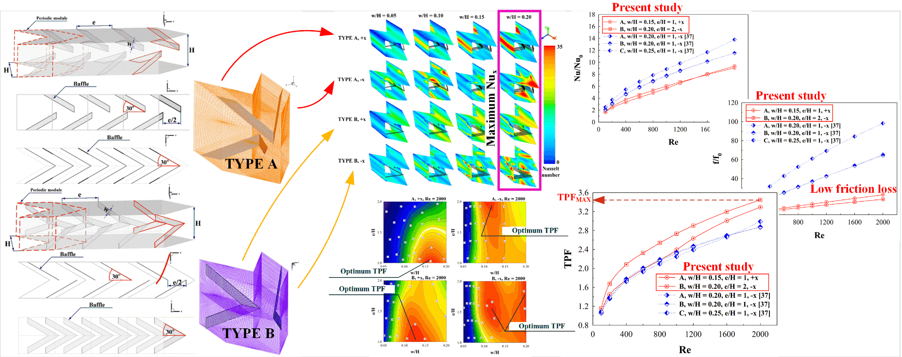
Thermal performance enhancement in a square channel heat exchanger (HX) using a passive technique is presented. Vortex turbulator insertion in a square channel HX as a passive technique is selected for thermal improvement. The vortex turbulator of interest is discrete X-V baffles (XVB). The discrete XVBs are inserted in the square channel with the main aim of generating vortex flow. The vortex flow generated can support the enhanced convective heat transfer coefficient and also enhance HX performance. Effects of baffle configuration (type A and B), baffle size (w/H = 0.05, 0.10, 0.15 and 0.20), baffle distance (e/H = 1, 1.5 and 2) and flow direction (±x air flow paths) on fluid flow and thermal topologies are numerically investigated by using a commercial code. As shown by the numerical results, the predicted flow configuration with the discrete XVB insertions, which include impinging and vortex streams, is found through the HX channel. The perturbing thermal boundary layer and greater air blending are also found through the HX channel inserted with the discrete XVB. These mechanisms promote and augment the convection heat transfer coefficient, heat transfer rate and rise thermal potentiality. The maximum Nusselt number of the channel with the baffles inserted is 11.01 times upper than that of the smooth channel, while the greatest thermal performance factor (TPF) is observed to be around 3.45.Graphic Abstract
Keywords
Nomenclature
| w | Discrete XVB thickness, m |
| Dh | Hydraulic diameter (= H) of the heat exchanger channel, m |
| f | Friction factor |
| H | Square channel height, m |
| h | Convective heat transfer coefficient, W m−2 K−1 |
| k | Thermal conductivity, W m−1 K−1 |
| L | Numerical model length/periodic length |
| Nu | Nusselt number |
| p | Static pressure, Pa |
| P | Pitch distance, m |
| Re | Reynolds number |
| T | Temperature, K |
| Mean velocity in tube, m s−1 | |
| ρ | Density, kg m−3 |
| Subscript | |
| 0 | Smooth square channel |
| pp | Pumping force |
| Abbreviation | |
| HX | Heat exchanger |
| SAH | Solar air heater |
| TPF | Thermal performance factor (=(Nu/Nu0)/(f/f0)1/3) |
Due to the increment of energy consumption in the present day, many industries have made many plans for energy conservation and management. One of the plans that has always been considered by the industries is performance improvements of engineering equipment and systems. Heat exchangers (HX) have been developed to improve their thermal performance. The improved HX performance can be achieved by various methods. Adding vibrating force to the HX is one method to improve HX performance. This is called “active technique”. Another method is called “passive technique”. The passive technique is an insertion/installation of small items in the HX sections to produce vortex flows that help to rise the convection heat transfer coefficient. The improved HX performance of many industries is always done with a passive method because the principal cost of energy for the operation has slightly change. The small parts inserted in the HX are called “vortex generators and turbulators”. Baffle [1–6], rib [7–13], groove [14–16], conical ring, etc., are types of vortex turbulators. The choice of vortex turbulators are based on the HX applications. Due to the popularity of the vortex turbulators for the thermal performance improvement, the vortex turbulator efficiency has been examined by many researchers.
For example, Singh et al. [17] reported thermal profiles, friction loss and thermal assessments through a double duct solar air heater (SAH) equipped with vortex producers (punched V-profile ribs). The 9.66-time augment in the SAH efficiency was concluded in their outcomes. The improvement of thermal efficiency of supercritical n-decane in cooling section HX applying triangular ribs for regenerative cooling was examined by Zhao et al. [18]. The outcomes showed that the ribbed channel can reach up to 2.04 times greater Nusselt number. Jiang et al. [19] investigated heat transfer and fluid flow configurations in a HX section equipped with various rib configurations. The V-profile ribs (with flow attack angle of 45°,60°,75°) and paralleled ribs (with flow attack angle of 45°, 60°, 75°, 90°) were considered with various studying settings. The 45° V-profile ribbed section provided the greatest cooling augmentation. The Nusselt number of the 45° V-profile ribbed channel is 33.8%–74% higher than that of the 90° paralleled ribbed channel. Zhang et al. [20] reported a CFD assessment through an SAH installed with transverse rib vortex turbulators for increasing thermal efficiency. From their investigations, they observed that the Nusselt number for their novel rib pattern was 1.9 times upper than that of the typical base case. Zhang et al. [21] investigated forced convection and fluid stream behaviors through a HX section equipped with micro V-profile rib vortex turbulators, dimple surface, and combined configurations (V-ribs with dimples). Their findings exhibited that the hybrid configuration (micro V-profile rib-dimple) provided even more pronounced heat transfer increment. Krishnaswamy et al. [22] offered the improvement of thermal efficiency within a gas turbine blade cooling applying V and W-profile ribs as a passive technique. The outcomes pointed out that the best augmenting heat transfer in the terms of Nusselt number ratio was observed to be around 3.9 for the V-profile ribs and 3.8 for the W-profile ribs. Moreover, the highest thermal performance was found to be around 3.3 for the V-profile rib and 3 for the W-profile rib turbulators. Jiang et al. [23] demonstrated the improvement of thermal potentiality in battery thermal management applying mini V-profile ribs. Zhu et al. [24] reported a simulation of thermal and fluid flow patterns within a HX channel installed with U-profile ribs as vortex producer. Lori et al. [25] studied Nusselt number augmentation through a microchannel HX applying porous ribs (with vertical arrangement) as generators. As their studies, the thermal potentiality of the porous-rib microchannel HX was found to be around 1.3–2.16 times higher than that of the reference (solid ribs), and 2.51–4.01 times upper than that of the plain microchannel HX without ribs. Kumar et al. [26] investigated HX performance of an SAH installed with vortex producers (discrete multi-arc ribs). From the results, the Nusselt number and friction loss ratios of their investigations were averaged to be around 7.61 and 6.48 times upper than that of the typical plain channel. Bhuvad et al. [27] presented an experimental examine within an SAH installed with arc rib (discrete configuration) vortex generators. The experimental outcomes pointed out that the new apex-up discrete arc rib provided upper thermal efficiency than the best existing apex-down ribs shapes. The greatest Nusselt number is observed to be around 2.92 times upper than that of the smooth plate case. Sujoy et al. [28] numerically studied flow configuration (laminar regime) through a HX section installed with vortex generators (transverse rib and helical screw tapes). The numerical outcomes presented the effect of generator size, spacing and screw tape placement on heat transfer and fluid stream characteristics. They also concluded that the thermal potentiality augmented with Reynolds number as well as rib height and it reduced with a rise in screw tape variables and rib distance. Zhao et al. [29] introduced the improvement of HX performance in an SAH using combined vortex turbulators (different profile ribs with delta-winglet). Their outcomes revealed that the delta-winglet with the 60° V-profile ribs yielded the best HX performance, and the thermal potency was rose by 39.4% when compared with that of the single turbulators (delta-winglets alone). Chang et al. [30] investigated aerothermal performance in a three-pass HX with pin-fins and ribs. From the investigations, they concluded that the heat transfer ability in the pin-fin tested-section in the effusion channel as compared with the non-effusion channel increased 1.68–1.44 times. Qi et al. [31] examined impacts of rib dimension with staggered placement on flow boiling and heat transfer within a heat sink equipment. The outcomes pointed out that the average Nusselt number increased and the wall temperature reduced with the rising rib diameter. Kumar et al. [32] illustrated the improvement of thermal ability within an SAH applying polygonal and trapezoidal profile rib as vortex producers. The optimal HX performance for their studying settings was 1.89. Zhao et al. [33] investigated impacts of micro rib turbulator on aerodynamic and thermal configuration through a HX channel. It is clear that based on the above literature, the micro rib turbulator is an efficient cooling technique to accomplish excellent thermal potentiality with a slight friction loss. Tanda et al. [34] presented thermal structures and fluid flow topologies within a HX section installed with angled and intersecting ribs. Their outcomes pointed out that the HX efficiency at an equal pumping power was enhanced for one intersecting rib case, while two intersecting ribs were unable to perform further augmentation.
As shown by past research, the V-shaped baffles/ribs are highly effective in improving in the HX performance. The V-shaped baffles can be placed on the tube/channel wall or installed in the middle/core of the tube/channel HX. The placement on the wall leads to upper heat transfer rate but with pressure drop. Installing V-shaped baffles is easier at the tube/channel core than on the wall, but it results in high pressure loss. In the present work, the V-shaped baffles are modified in order to achieve three goals: 1. to increase heat transfer rate, 2. to maintain or achieve lower pressure loss than the general V-shaped baffles, and 3. to ease an installation and maintenance. The modified V-shaped baffle is named “X-V baffle (XVB)”. Effects of XVB widths, configurations, placements and flow paths on thermal configuration and flow structure within the HX square channel are numerically investigated. Laminar air flow with Reynolds number in a range of 100–2,000 (based on inlet conditions) is considered. The numerical study [35] can help to describe thermal and flow mechanisms and offer insights needed for further improvements of heat exchangers and vortex turbulators.
2 Numerical Models and Discrete X-V Baffle Configurations
Figs. 1a and 1b present typical configurations of XVB and discrete XVB for types A and B, respectively. The discrete XVB is developed with the aim to reduce pressure loss and enhance mixing quality in the HX channel. The decrease in pressure loss and the enhancement of fluid mixing quality are two key factors contributing to greater HX performance. Figs. 2a and 2b show the square channel HX installed with the discrete XVB for type A and B, respectively. The HX channel height, H, equals to 5 cm. The hydraulic diameter of the HX square channel, Dh, is equivalent to H. The ratios of discrete XVB width, w, to the channel height, w/H, are varied in the range of 0.05–0.20. The ratios of discrete XVB distance, e, to the channel height, e/H, in the present are equal to 1, 1.5 and 2. Positive and negative x-axis are the two air stream directions examined. The distance of the opposite baffles is equal to e/2. The air flow is laminar with the Reynolds number of 100 to 2,000.
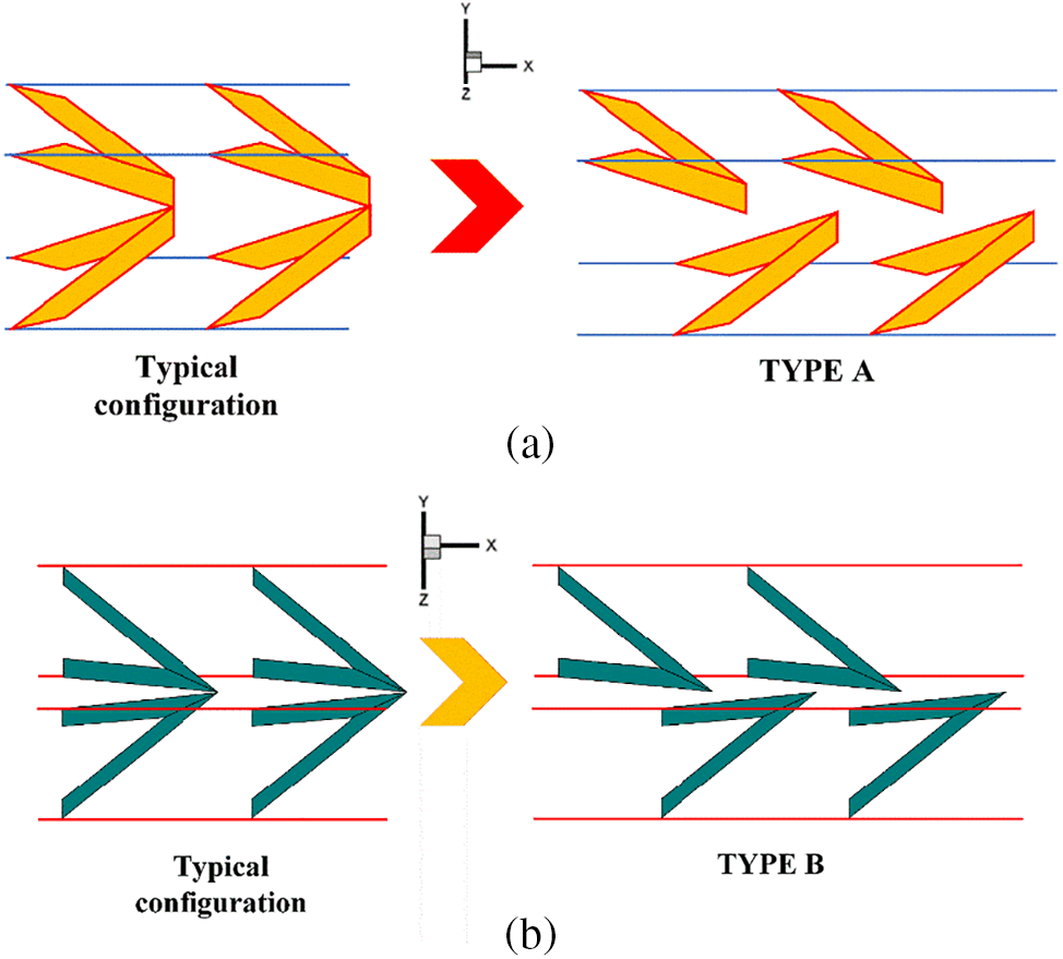
Figure 1: Typical configuration of XVB and discrete XVB for (a) Type A-discrete XVB and (b) Type B-discrete XVB
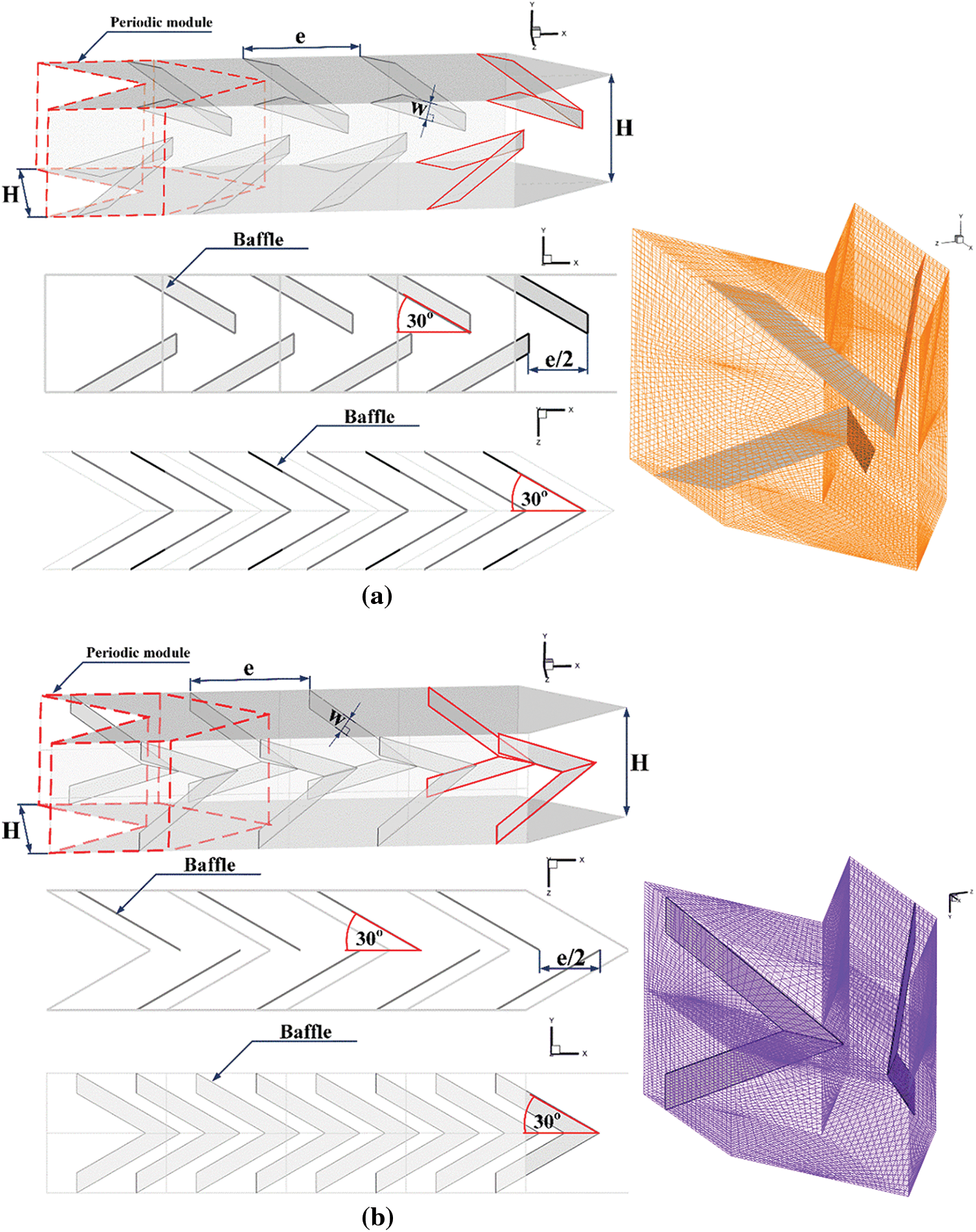
Figure 2: HX square channel installed with discrete XVB and the computational domain for (a) Type A-discrete XVB and (b) Type B-discrete XVB
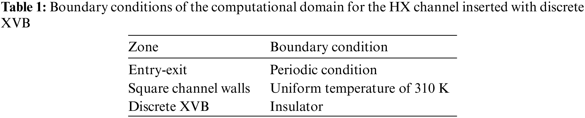
3 Boundary and Initial Conditions
The air, which is the working fluid, with a primary temperature of 300 K flows into the HX channel. The air properties are set with constant values at the average bulk mean temperature because the air temperature difference (ΔT) is less than 10 K. A no-slip wall condition is applied for all computational surfaces. For heat transfer modes, forced convective heat transfer within the HX channel is measured, while thermal radiation and natural-convection heat-transfer are not accounted. Body force and viscous dissipation are measured to be insignificant. The steady-state air flow through the HX channel is assumed and examined in three dimensions as well as heat transfer. The boundary conditions of the computational domain are presented in Table 1.
4 Mathematical Foundation and Numerical Method
With the above presumptions and initial conditions, the governing equations are the continuity equation, the momentum equation and the energy equation which can be printed in tensor form as presented in Eqs. (1)–(3), respectively [36].
where, Γ represents the thermal diffusivity which is illustrated as Eq. (4).
A commercial code/program (finite volume method) is used to numerically study the present work. The numerical settings are referred from reference [37].
In the current research, dimensionless variables are selected for the analysis. The fluid velocity at the computational inlet is illustrated in terms of Reynolds number (Re). Eq. (5) presents the calculation of the Reynolds number [36].
Reynolds number:
The pressure drop or pressure loss across the discrete XVB is evaluated by the friction factor (f). Eq. (6) presents the calculation of the friction factor [36].
Friction factor:
Local Nusselt number (Nux) and averaged Nusselt number (Nu) are presented in Eqs. (7) and (8), respectively, which are selected to describe the heat transfer in the HX channel [36].
Local Nusselt number:
Averaged Nusselt number:
The discrete XVB in the HX channel rises both Nusselt number and friction loss. The thermal efficiency of discrete XVB can be calculated from the increase of Nusselt number and friction factor at an equal pumping power which is called thermal performance factor (TPF) [37] as shown in Eq. (9).
Thermal performance factor:
Nu0 and f0 represent Nusselt number and friction factor of the plain channel without the discrete XVB, respectively.
Two sets of computational validations were conducted: smooth channel validation and optimum grid elements.
The heat transfer and pressure loss value from the current research are compared with the correlation data [36]. The heat transfer ability is reported in terms of Nusselt number, while the pressure loss is represented by the friction factor. The validation results show that the Nusselt number and the friction factor of the current predictions follow similar trends with that of the correlation data. The Nusselt number is found to be constant when increasing the Reynolds number, while the friction factor decreases when augmenting the Reynolds number. The deviations between the present predictions and correlation data are around ±0.5% and ±2% for the Nusselt number and the friction factor, respectively (see Fig. 3).
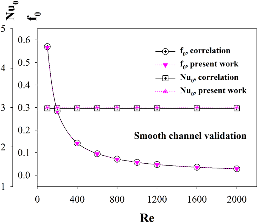
Figure 3: Numerical validations: Smooth channel validation
To select the optimal grid elements, the computational domains of the HX channel inserted with discrete XVBs (type A, w/H = 0.15, e/H = 1 and +x air flow direction) with various grid elements; 80000, 120000, 240000, 360000 and 480000, are compared. The increasing grid elements of the HX channel inserted with the discrete XVBs from 120000 to 480000 has no effect on heat transfer and friction loss (see Fig. 4). Thus, the computational domains are developed under grid elements around 120000 for all cases.
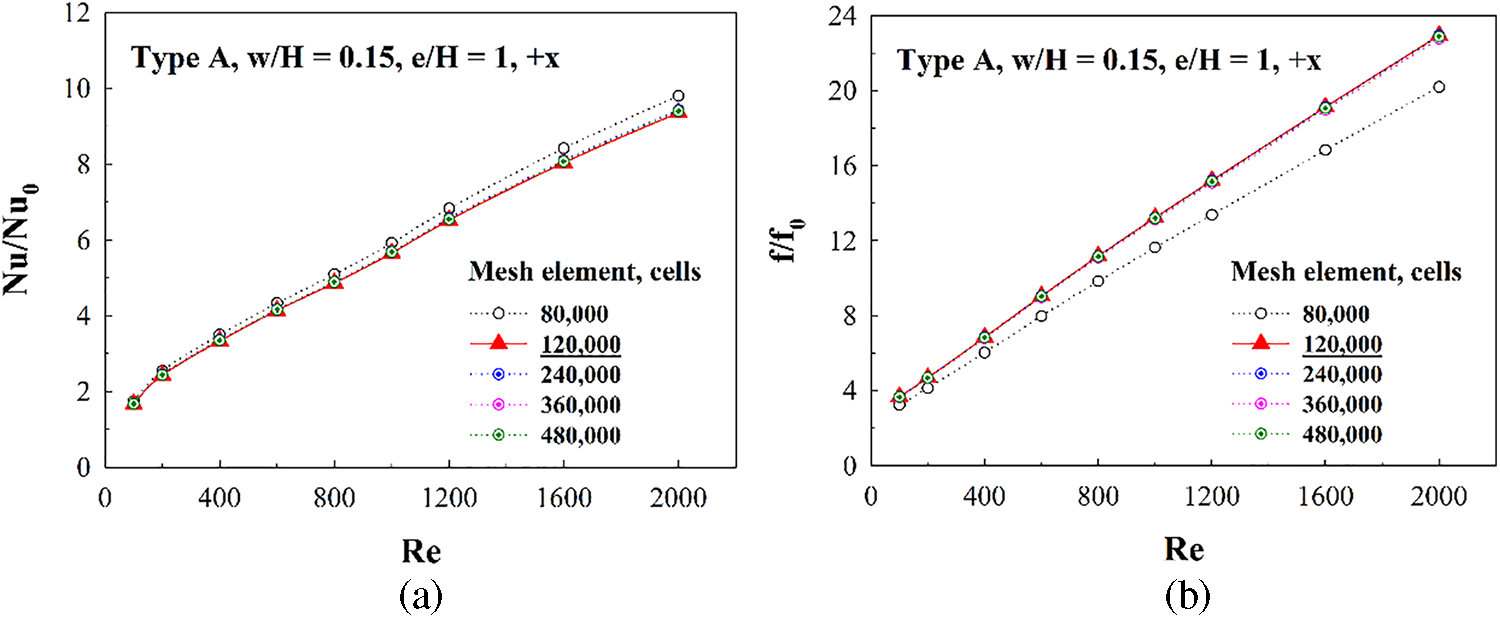
Figure 4: Numerical validations: Grid independence/optimum grid elements (type A discrete XVB, w/H = 0.15, e/H = 1 and +x air flow direction) for (a) Nu/Nu0 and (b) f/f0
From the numerical validations, it can be concluded that the validated model is reliable for predicting the flow and heat transfer.
Numerical results focus on the air flow structures and thermal profiles within the HX channel inserted with discrete XVBs. The understanding and knowledge of air flow structures and thermal behaviors are crucial for improving vortex turbulators and HX performance.
6.1 Air Flow and Heat Transfer
Air flow, temperature contours and Nusselt number contours in the tested channel are illustrated in this section. Figs. 5a and 5b present the streamlines in cross sectional planes of air flow along the tested channel inserted with type A discrete XVBs plotted in the +x and −x fluid flow paths, respectively. As depicted in the figures, the generated vortex flows are obviously found along the tested channel in both flow directions. The four vortex cores and small vortices near the channel corners are clearly found. The vortex core position changes depending on the x/H position. The symmetrical flow at the left and right sections is observed due to the symmetric baffle configuration. At the cross-sectional planes, the flow rotation is in the opposite direction when the flow path changes.
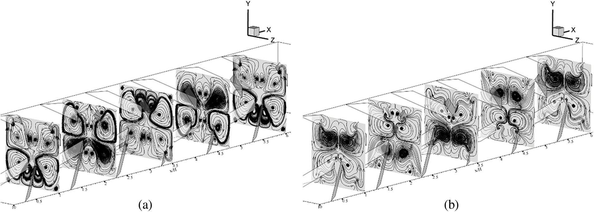
Figure 5: Air flow configuration in y-z planes when w/H = 0.15, e/H = 1 and Re = 600 for type A discrete in (a) the +x fluid flow direction and (b) the −x fluid flow direction
Figs. 6a and 6b show the streamlines in transverse planes of the air flow in the HX channel inserted with type B XVBs in the +x and −x flow paths, respectively. As seen in the figures, the vortex flows are produced along the tested section in both air flow directions. There are four major vortex cores and small vortices close to the channel walls and corners. The vortex core position changes depending on the x/H position in the tested channel. The air flow structure is found to be symmetrical at the upper and lower paths of the y-z plane due to the symmetrical configuration of discrete XVBs in both air flow paths.
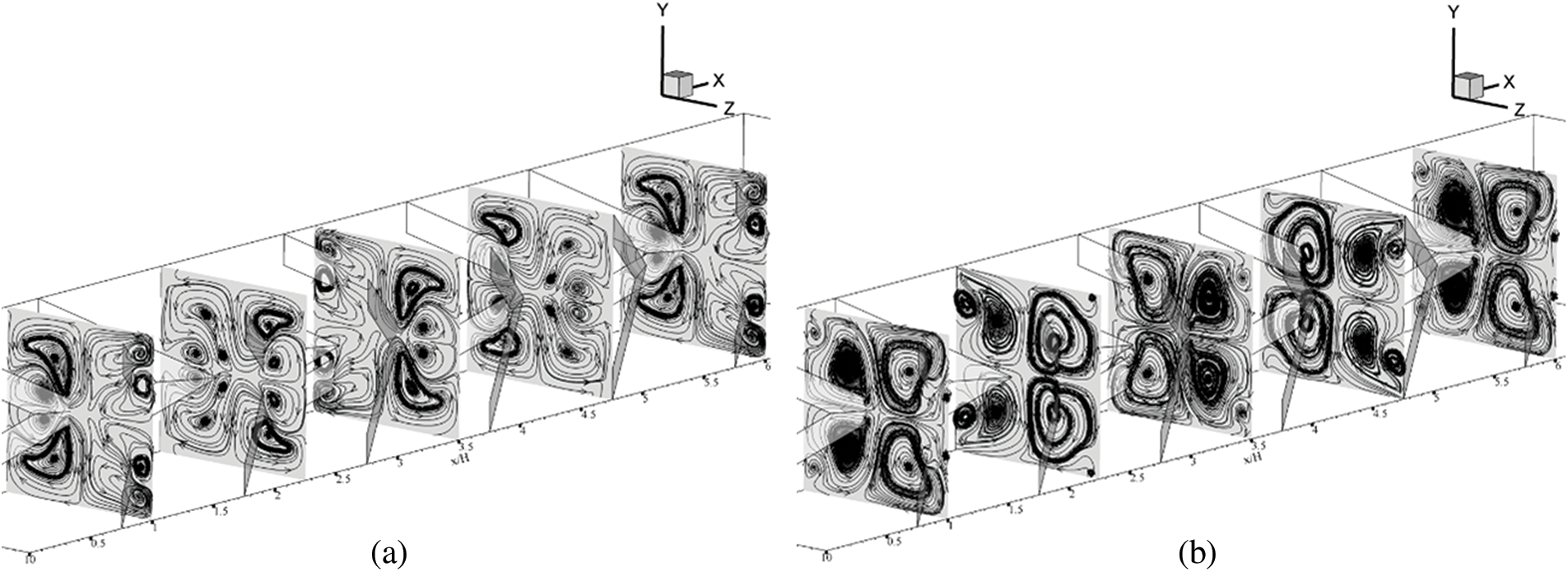
Figure 6: Air flow configuration in y-z planes when w/H = 0.15, e/H = 1 and Re = 600 for type B discrete in (a) the +x fluid flow direction and (b) the −x fluid flow direction
The vortex flows are the important key elements of a passive technique applied to improve HX performance. Parts of the vortex streams impinging on the channel walls are named “impinging flow”. The impinging flows disturb the thermal boundary layer over the channel walls (heat transfer surfaces), thus enhancing the convective heat transfer coefficient (see Fig. 7). The enhanced convective heat transfer coefficient leads to an increase in the heat transfer ability.
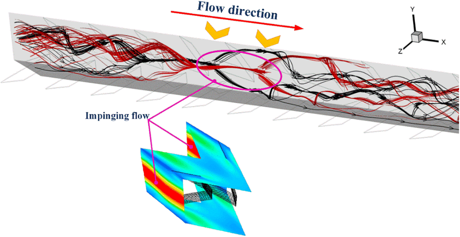
Figure 7: Relation of impinging flows with the highest Nusselt number contours (the red contours)
Moreover, other parts of the vortex streams can help to improve air mixing quality which also increases the heat transfer rate. The increase in air mixing quality can be seen in Figs. 8 and 9 which plotted the air temperature distributions in y-z planes for type A and B discrete XVBs, respectively. High air temperature (310 K) is plotted with red contours, while low air temperature (300 K) is plotted with blue contours. The insertion of discrete XVBs enhances the fluid mixing quality for all investigated cases. The red layer thickness close to the HX channel walls obviously declines, while the blue contours expand from the channel center to the channel walls.
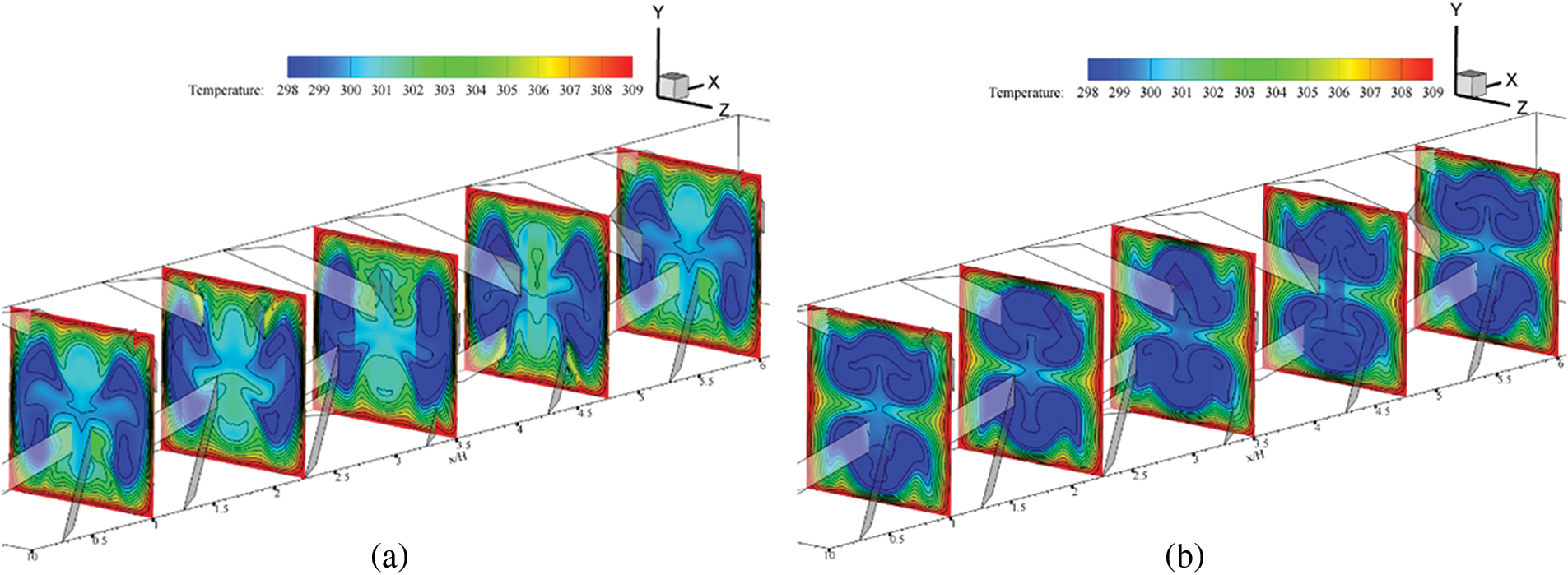
Figure 8: Air temperature contours in y-z planes when w/H = 0.15, e/H = 1 and Re = 600 for type A discrete in (a) the +x fluid flow direction and (b) the −x fluid flow direction
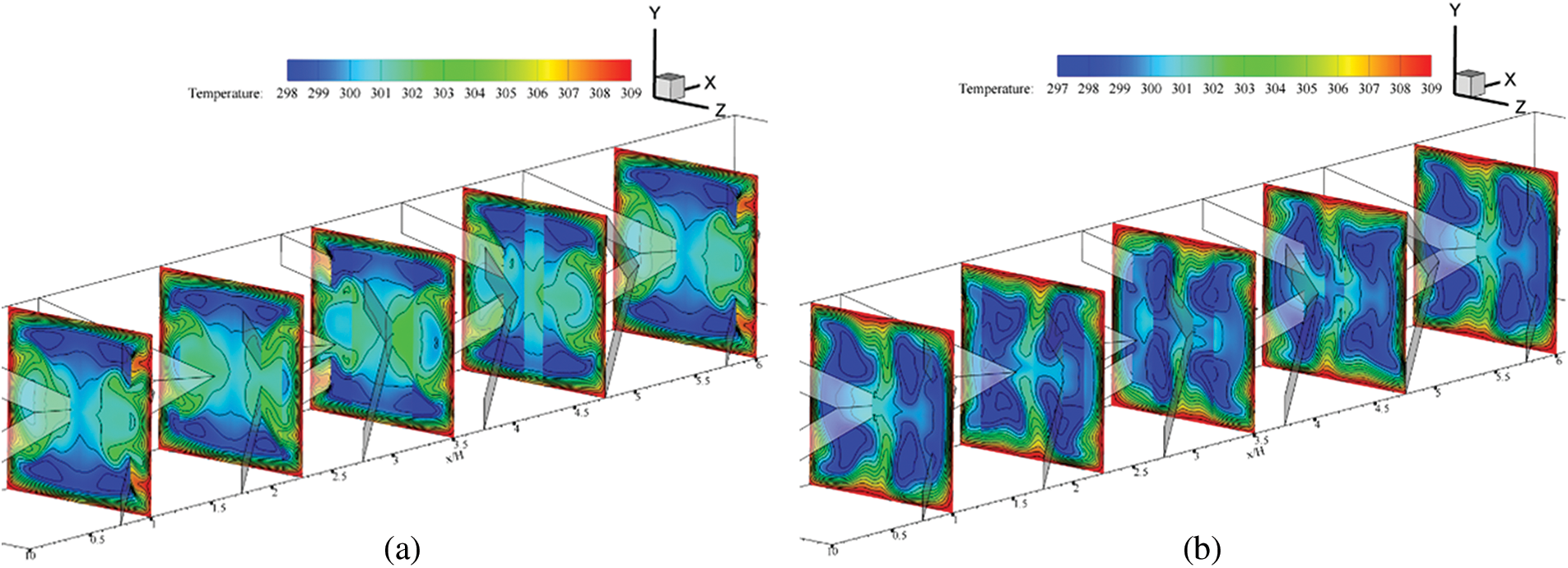
Figure 9: Air temperature contours in y-z planes when w/H = 0.15, e/H = 1 and Re = 600 for type B discrete in (a) the +x fluid flow direction and (b) the −x fluid flow direction
The increase in heat transfer rate of the HX square channel after installing the discrete XVBs can be observed from the local Nusselt number contours on the HX channel walls which are shown in Fig. 10. The channel with the discrete XVBs achieves better heat transfer rates as compared with the general square channel with no vortex turbulators in all investigated cases. For all XVB types in both flow directions, the Nusselt number increases when w/H is greater because of an increase in vortex strength. The increase in vortex strength directly increases heat transfer coefficient. This explains the higher thermal ability and Nusselt number augmentations. The highest local Nusselt number is related to the impinging regime of the vortex flow. The regimes of impingement change when the discrete XVB types, flow paths and w/H change due to the variations of thermal and flow behaviors. The cases of e/H = 1.5 and 2 exhibit similar trends of thermal and flow behaviors for the case of e/H = 1.
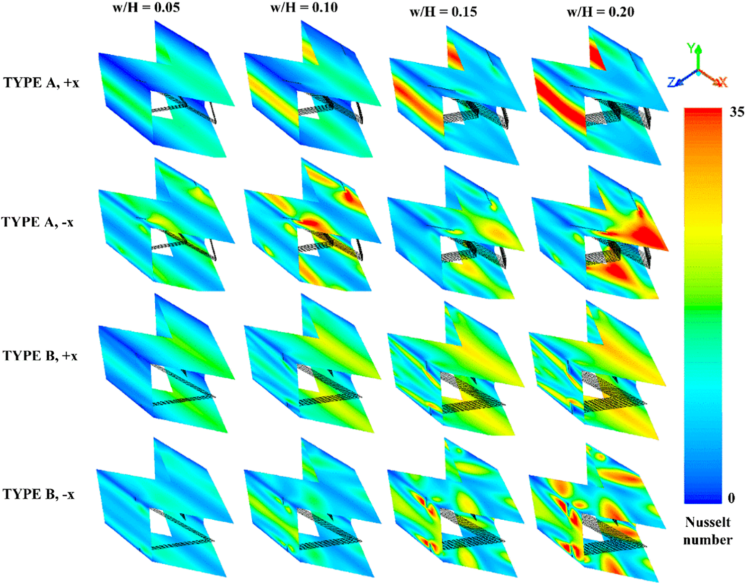
Figure 10: Local Nusselt number (Nux) contours of the HX square channel equipped with discrete XVB for various cases
Performance assessment of the HX square channel installed with the discrete XVBs is performed by heat transfer ability, pressure loss and thermo-hydraulic performance. The heat transfer is evaluated with Nusselt number (Nu), while the pressure loss and thermo-hydraulic performance are assessed by friction factor (f) and thermal performance factor (TPF), respectively.
Fig. 11 shows the relationship between Nu/Nu0 and the Reynolds number from various investigated cases. The Nu/Nu0 increases with the Reynolds number and w/H values because of the increase in vortex strength. The channel with discrete XVBs achieves much higher heat transfer rate as compared with the smooth channel with no vortex turbulator. The Nu/Nu0 is much higher than 1 in all cases. The air flow directions slightly affect the Nusselt number. When e/H = 1, the Nu/Nu0 equals 1.29–10.37, 1.03–9.33, 1.35–9.88 and 1.23–11.01 for type A (+x flow path), type A (−x flow path), type B (+x flow path) and type B (−x flow path), respectively. In the case of type A discrete XVBs, e/H = 1 provides a greater Nusselt number than e/H = 1.5 and 2 by 16% and 24%, respectively. As for the case of type B discrete XVBs, e/H = 1 offers a greater heat transfer rate than e/H = 1.5 and 2 by 14% and 24%, respectively, in the +x fluid path, and 11% and 18% in the −x flow direction. The maximum Nu/Nu0 for the present investigations is 10.37 (observed from the cases of type A discrete XVBs, in the +x fluid flow direction, e/H = 1 and w/H = 0.20).
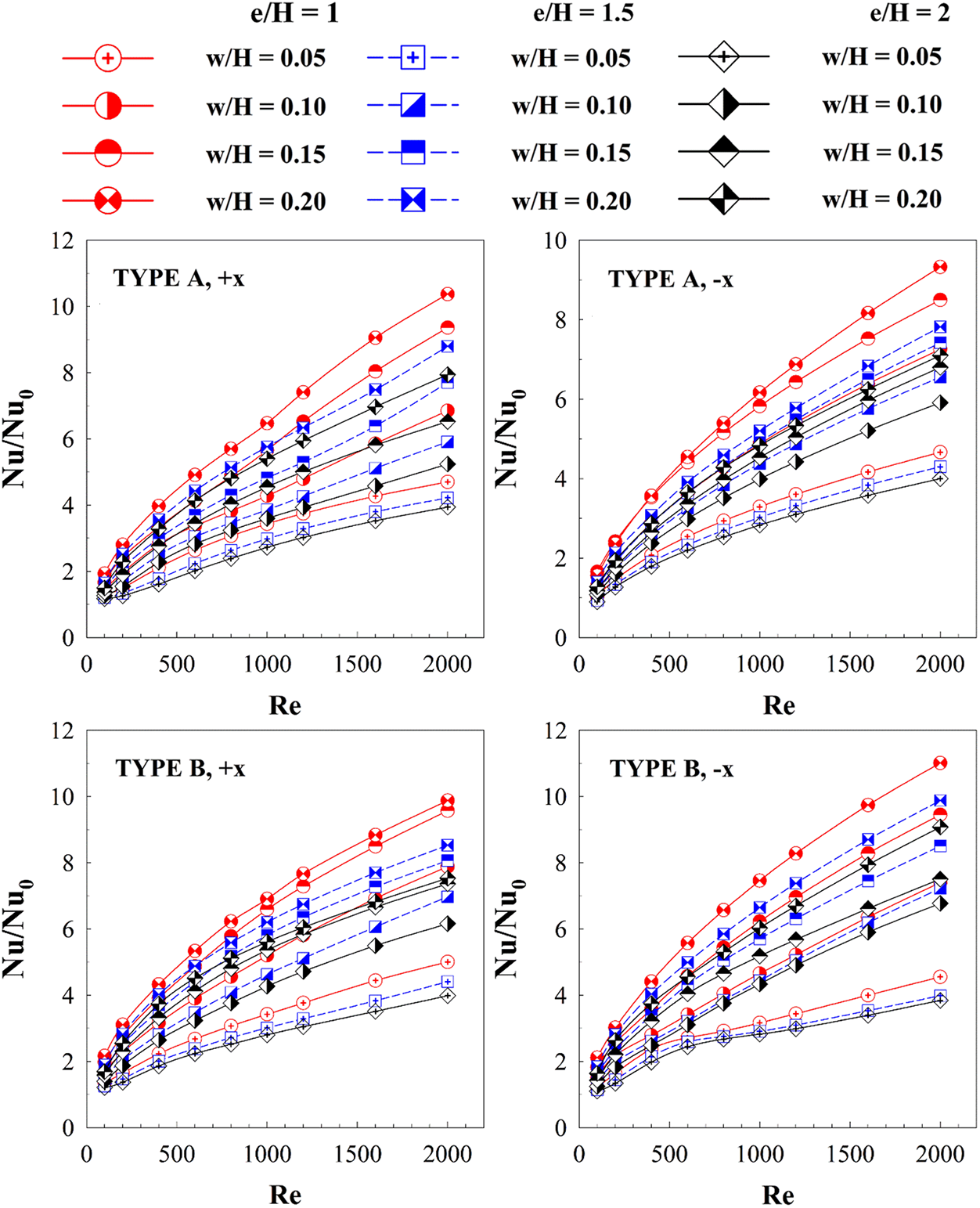
Figure 11: Relations of Nu/Nu0 with Re at different cases
The discrete XVB insertion gives not only a much greater heat transfer ability compared with the plain square channel, but also results in higher friction loss. The relationship between f/f0 and the Reynolds number in the square channel inserted with different types of discrete XVBs and with various e/H, w/H, and air flow directions are presented in Fig. 12. As observed in the figure, the f/f0 rises when Reynolds number and w/H increase. The change in flow directions and types of discrete XVBs have a slight effect on f/f0. f/f0 is 1.84–34.14 for type A (+x flow path), 1.87–30.22 for type A (−x flow path), 1.69–28.82 for type B (+x flow path) and 1.71–35.57 for type B (−x flow path).
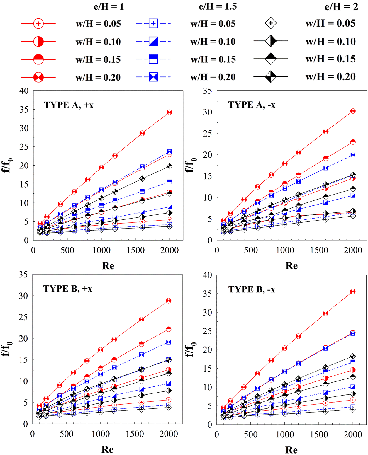
Figure 12: Relations of f/f0 with Re at different cases
6.2.3 Thermal Performance Factor
Because the discrete XVBs lead to both higher heat transfer rates and friction loss, the thermal performance (at the identical pumping force), which is called “thermal performance factor or TPF”, is reported to describe their benefits. The variation of the TPF with the Reynolds number is plotted in Fig. 13. As shown in the figure, the TPF increases with the Reynolds number. The maximum TPF is observed when Re = 2000, while the minimum TPF is observed when Re = 100. In almost all cases, the discrete XVBs result in better TPF than the smooth square channel with no vortex turbulator. The best TPF of 3.29 is observed in the case of type A discrete XVBs when w/H = 0.15 and e/H = 1 in the +x air flow direction, and when w/H = 0.10 and e/H = 2 in the −x fluid flow direction, the best TPF of 3.12 is observed. For type B discrete XVBs, the optimum TPF of 3.41 is observed when w/H = 0.15 and e/H = 1 in the +x fluid flow path, and in the −x air flow, the best TPF of 3.45 is observed when w/H = 0.20 and e/H = 2.
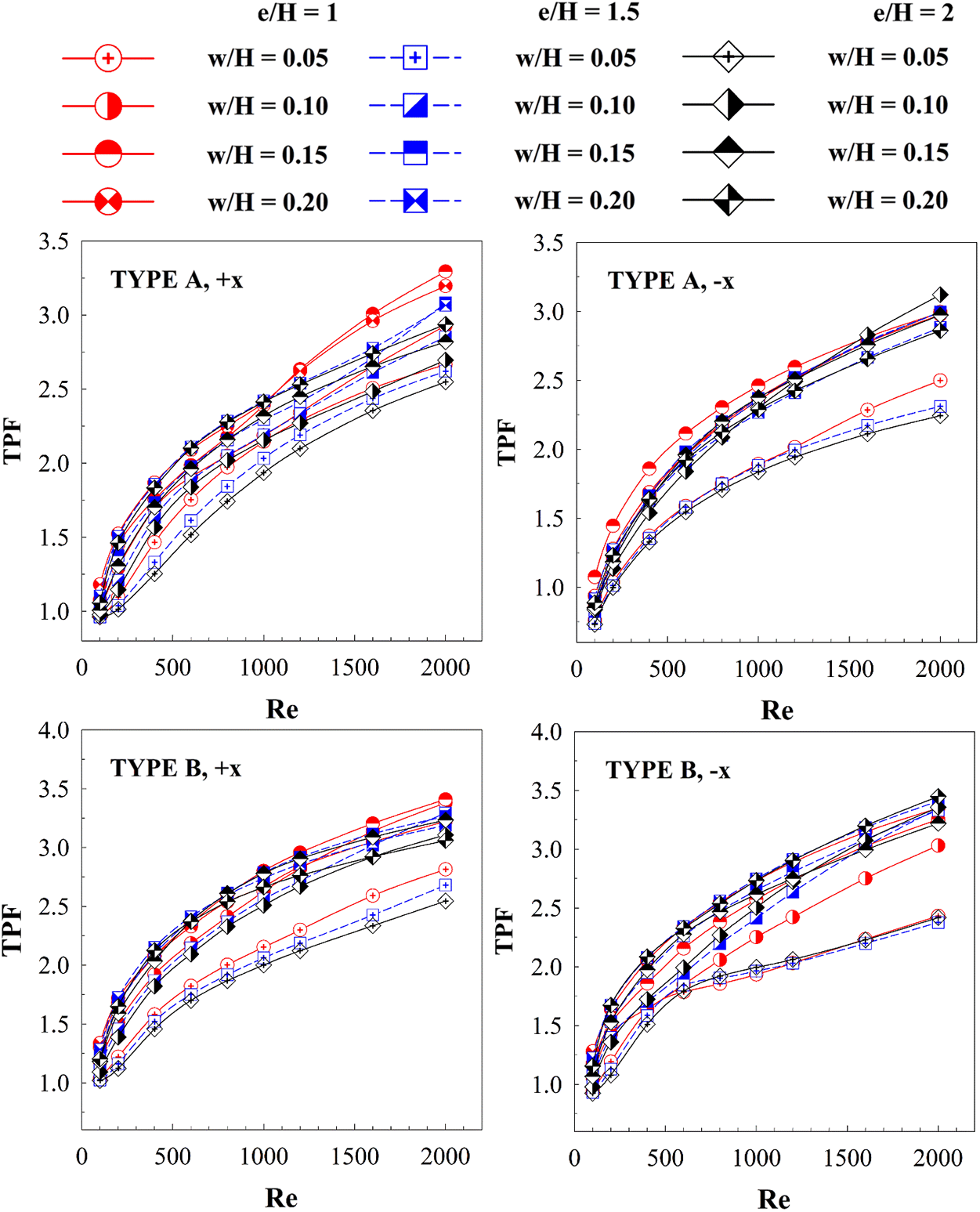
Figure 13: Relations of TPF with Re at various cases
Fig. 14 plots the relationship among the Nu/Nu0, f/f0 and TPF and the Reynolds number at different e/H, w/H, air flow directions and discrete XVB types. It is clearly seen that the reduction of the e/H has an effect on the Nusselt number and the friction factor. The vortex strength increases when the e/H value decreases, which explains the rise in the Nusselt number and friction loss. The changes in TPF at various e/H values similar. More specifically, the maximum TPF at different e/H values is very close to one another.
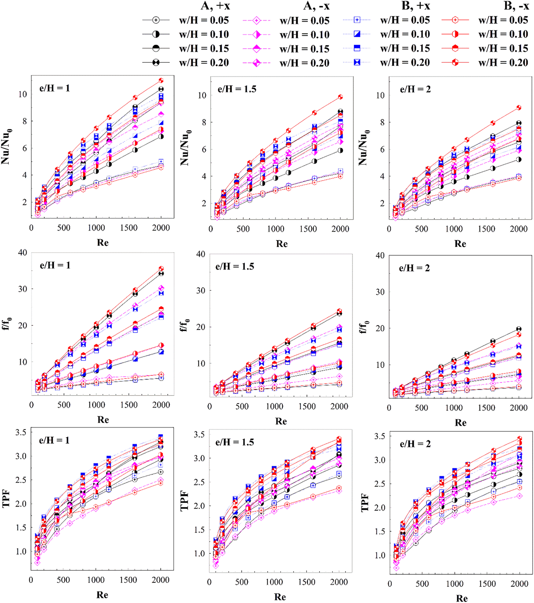
Figure 14: Performance assessment (Nu/Nu0, f/f0 and TPF) of the HX square channel equipped with discrete XVBs
Numerical predictions of air flow and thermal behavior in the HX square channel equipped with the discrete XVBs are studied. The effects of width ratios (w/H = 0.05, 0.10, 0.15 and 0.20), pitch ratios (e/H = 1, 1.5 and 2), discrete XVB types (types A and B), air flow directions (+x and −x) on thermal and flow behaviors are examined in the laminar regime (Re = 100–2000). The major findings of the current work can be concluded as follows.
The effects of the discrete XVB in the HX channel are as predicted. The produced vortex flows are observed for both discrete XVB types. Some sections of the vortex streams bounce on the HX channel walls, which is named “impinging flows”. The impinging vortex flows cause the thermal boundary layer disturbance. The disturbed thermal boundary layer directly increases the convective heat transfer coefficient, which is the main cause of the heat transfer rate increment. Other sections of the vortex flow at the channel core can help to improve air mixing quality, another factor which improves the heat transfer potency of the HX channel.
The vortex strength which can be increased not only by increasing in w/H and Re but also reducing e/H is essential to the greater heat transfer rate. In addition, different types of discrete XVBs and air flow paths affect the fluid flow and thermal structures. The maximum TPF of 3.45 is observed when e/H = 2, w/H = 0.20, in the −x direction for types B discrete XVBs. The best heat transfer rate when w/H = 0.20, e/H = 1, −x air flow for types B discrete XVBs is 11.01 times higher than that of the smooth channel.
Fig. 15 shows the TPF contours of various cases at the highest Reynolds number (Re = 2000). For type A discrete XVBs, the best TPF is observed when e/H = 1 and w/H = 0.15 and 0.10–0.15 in the +x and −x air flow directions, respectively. For type B discrete XVB in the +x flow direction, the optimum TPF of 3.4 is observed when e/H = 2 and w/H = 0.10–0.15. However, the TPF of 3.2–3.4 is clearly high for most cases of w/H and e/H for the type B discrete XVBs.
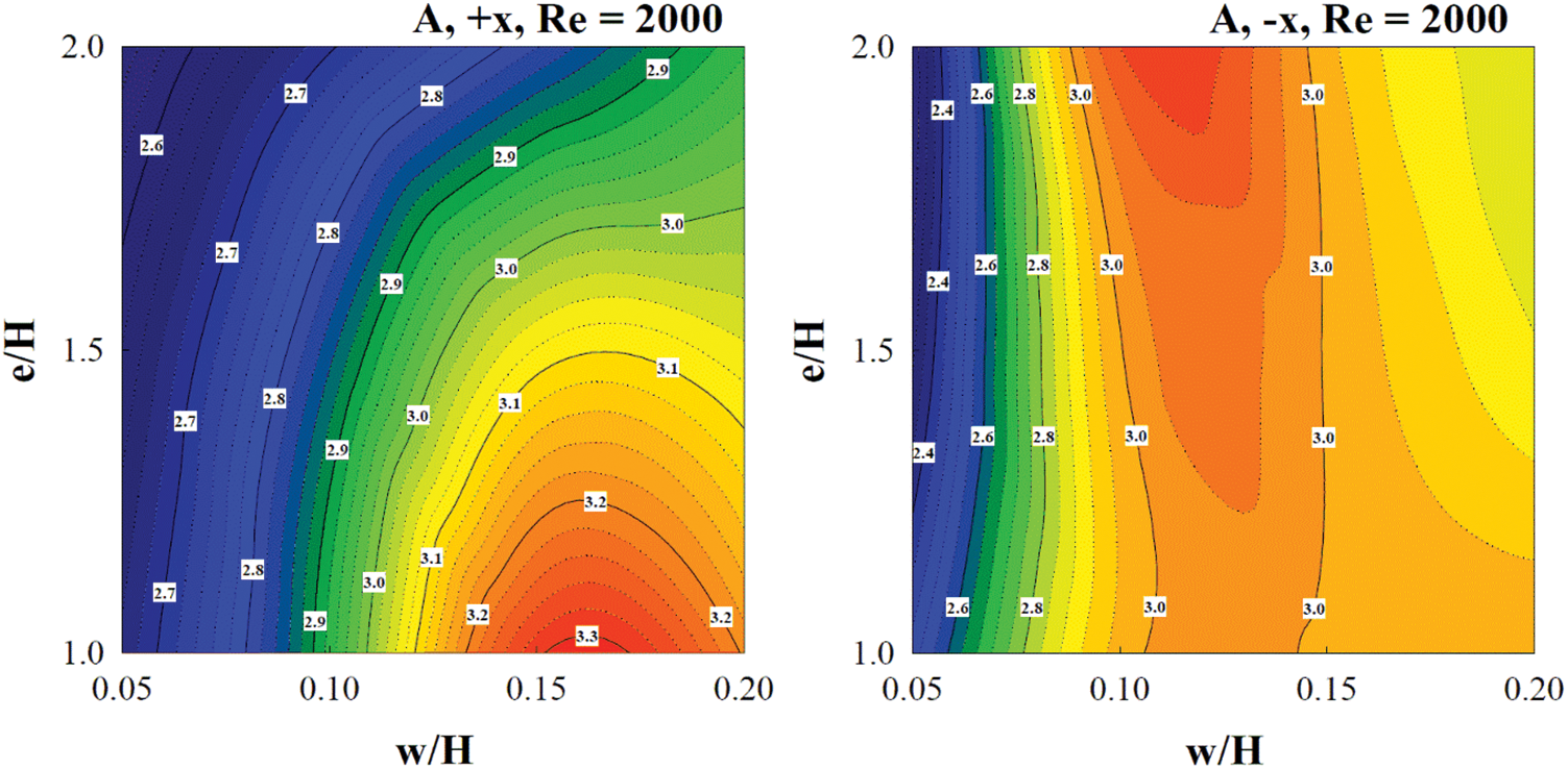
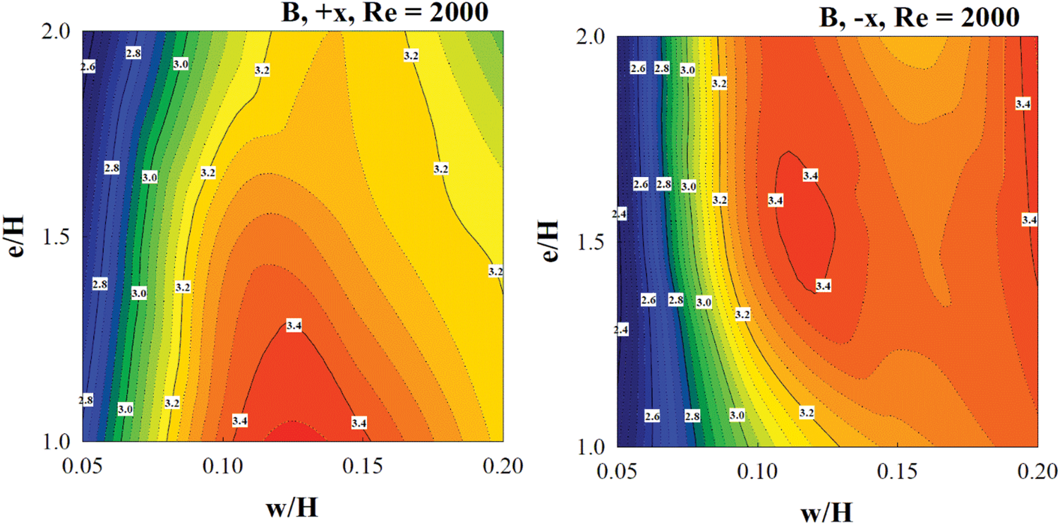
Figure 15: TPF contours at Re = 2000
The comparisons of Nu/Nu0, f/f0 and TPF between the present work and the published work [37] are reported as Figs. 16a–16c, respectively. The present work performs lower Nusselt number and friction loss than the published work [37] around 14.14%–38.86% and 50.92%–82.54%, respectively. In addition, the present work yields higher TPF than the previous work [37] around 18.75% when considering at Re = 2000.
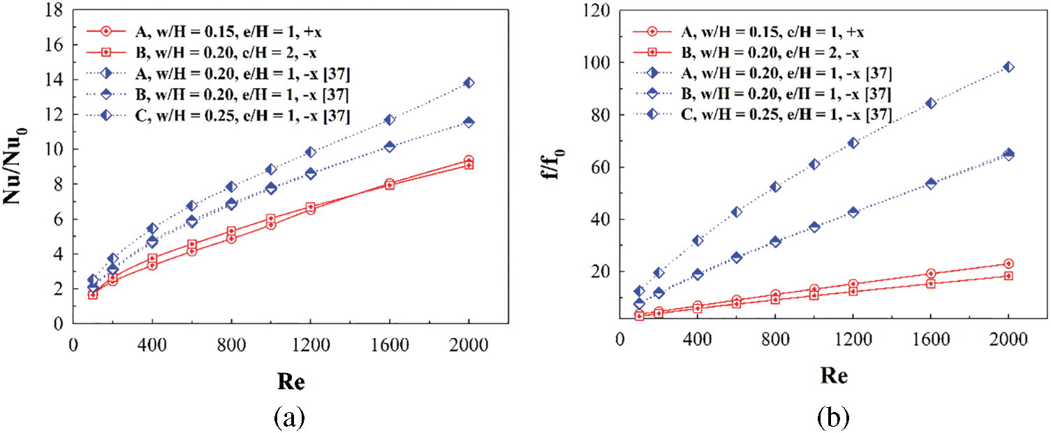
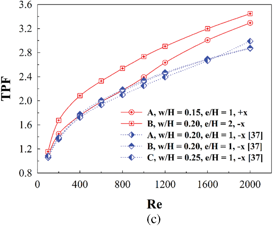
Figure 16: Comparison between the current and published researches for (a) Nu/Nu0, (b) f/f0 and (c) TPF
Acknowledgement: The authors would like to thank Prof. Dr. Pongjet Promvonge for suggestions.
Funding Statement: The authors received no specific funding for this study.
Author Contributions: The authors confirm contribution to the paper as follows: study conception, design, data collection: A. Boonloi; analysis and interpretation of results and draft manuscript preparation: W. Jedsadaratanachai. All authors reviewed the results and approved the final version of the manuscript.
Availability of Data and Materials: No data was used for the research described in the article.
Conflicts of Interest: The authors declare that they have no conflicts of interest to report regarding the present study.
References
1. Phila, A., Keaitnukul, W., Eiamsa-ard, S., Naphon, P., Maruyama, N. et al. (2023). Influence of notched baffles on aerothermal performance behaviors in a channel. Case Studies in Thermal Engineering, 47, 103070. [Google Scholar]
2. Oloruntoba, A., Zhang, Y., Li, S. (2023). Performance evaluation of gas maldistribution mitigation via baffle installation: Computational study using ozone decomposition in low-velocity dense fluidized beds. Chemical Engineering Research and Design, 195, 38–53. [Google Scholar]
3. Wang, J., Gao, J., Sun, Y. (2023). Semi-analytical method for liquid sloshing in the rigid super-elliptical tank with the ring baffle. Ocean Engineering, 281, 114718. [Google Scholar]
4. Asgari, B., Hakkaki-Fard, A., Hannani, S. K. (2023). Effect of baffle turbulators on the horizontal solar film evaporator of the humidification-dehumidification desalination system. Thermal Science and Engineering Progress, 42, 101888. [Google Scholar]
5. Darbari, B., Ayani, M. B. (2023). Heat transfer and deposition analysis of CuO-Water nanofluid inside a baffled channel: Two-phase Eulerian-Lagrangian method. Journal of the Taiwan Institute of Chemical Engineers, 148(2), 104827. [Google Scholar]
6. Eiamsa-ard, S., Phila, A., Wongcharee, K., Pimsarn, M., Maruyama, N. et al. (2023). Thermal evaluation of flow channels with perforated-baffles. Energy Reports, 9(3), 525–532. [Google Scholar]
7. Wang, J., Deng, X., Jia, D., Lei, J., Xie, G. (2023). Numerical investigation on effects of rib shapes on oscillating flow and heat transfer in heat exchanger channels. Thermal Science and Engineering Progress, 42, 101919. [Google Scholar]
8. Bhuvad, S. S., Rizvi, I. H., Azad, R. (2023). Apex-up discrete-arc rib roughened solar air heater-energy and exergy based experimental study. Solar Energy, 258, 361–371. [Google Scholar]
9. Javanmard, S., Ashrafizadeh, A. (2023). A comparative numerical study on heat transfer and pressure drop characteristics of perforated ribs. International Journal of Thermal Sciences, 191, 108373. [Google Scholar]
10. Tang, J., Yuan, N., Zhai, Y., Li, Z. (2023). Effect of discrete inclined ribs on flow and heat transfer of supercritical R134a in a horizontal tube. The Journal of Supercritical Fluids, 200, 105980. [Google Scholar]
11. Ling, B., Feng, Z., Lin, Q., Wang, Z., Guo, F. et al. (2023). Comparative study on hydrothermal characteristics in straight, divergent and convergent minichannels having ribs with various heights along-channel. International Journal of Thermal Sciences, 187, 108190. [Google Scholar]
12. Tanda, G., Ahmed, E. N., Bottaro, A. (2023). Natural convection heat transfer from a ribbed vertical plate: Effect of rib size, pitch, and truncation. Experimental Thermal and Fluid Science, 145, 110898. [Google Scholar]
13. Xie, G., Lei, J., Deng, X., Wang, J., Chen, H. (2023). Numerical investigation on two-phase oscillating flow and heat transfer enhancement for a cooling channel with ribs. International Journal of Thermal Sciences, 187, 108191. [Google Scholar]
14. Miansari, M., Hasanpour, R., Alizadeh, A., Toghraie, D., Akbari, O. A. (2023). Numerical analysis of heat transfer enhancement in grooved vertical multi-cylinders at various groove geometries. Alexandria Engineering Journal, 70, 535–546. [Google Scholar]
15. Samadi, H., Hosseini, M. J., Ranjbar, A. A., Pahamli, Y. (2023). Thermohydraulic performance of new minichannel heat sink with grooved barriers. International Communications in Heat and Mass Transfer, 144, 106753. [Google Scholar]
16. Siriyothai, P., Kittichaikarn, C. (2023). Performance enhancement of a galloping-based energy harvester with different groove depths on square bluff body. Renewable Energy, 210, 148–158. [Google Scholar]
17. Singh, V. P., Jain, S., Karn, A., Dwivedi, G., Kumar, A. et al. (2022). Heat transfer and friction factor correlations development for double pass solar air heater artificially roughened with perforated multi-V ribs. Case Studies in Thermal Engineering, 39, 102461. [Google Scholar]
18. Zhao, J., Li, S., Zhang, X., Sun, M., Song, Y. (2023). Enhanced heat transfer of supercritical n-decane in cooling channels with triangular ribs for regenerative cooling. Applied Thermal Engineering, 218, 119369. [Google Scholar]
19. Jiang, G., Gao, J. (2022). Flow and heat transfer performance of the channel with different shaped ribs cooled by mist/steam two-phase flow. Case Studies in Thermal Engineering, 38, 102365. [Google Scholar]
20. Zhang, P., Xia, P., Guo, X., Xie, S., Ma, W. (2022). A CFD-adjoint reverse design of transverse rib profile for enhancing thermo-hydraulic performance in the solar air heater. Renewable Energy, 198, 587–601. [Google Scholar]
21. Zhang, P., Rao, Y., Xie, Y., Zhang, M. (2021). Turbulent flow structure and heat transfer mechanisms over surface vortex structures of micro V-shaped ribs and dimples. International Journal of Heat and Mass Transfer, 178, 121611. [Google Scholar]
22. Krishnaswamy, K., Sivan, S. (2021). Improvement in thermal hydraulic performance by using continuous V and W-Shaped rib turbulators in gas turbine blade cooling application. Case Studies in Thermal Engineering, 24, 100857. [Google Scholar]
23. Jiang, W., Zhao, J., Rao, Z. (2021). Heat transfer performance enhancement of liquid cold plate based on mini V-shaped rib for battery thermal management. Applied Thermal Engineering, 189, 116729. [Google Scholar]
24. Zhu, F., Jing, Q., Xie, Y., Zhang, D. (2022). Numerical investigation on flow and heat transfer characteristics of U-shaped channels with side-wall column ribs. International Communications in Heat and Mass Transfer, 137, 106221. [Google Scholar]
25. Lori, M. S., Vafai, K. (2022). Heat transfer and fluid flow analysis of microchannel heat sinks with periodic vertical porous ribs. Applied Thermal Engineering, 205, 118059. [Google Scholar]
26. Kumar, R., Kumar, S., Nadda, R., Kumar, K., Goel, V. (2022). Thermo-hydraulic efficiency and correlation development of an indoor designed jet impingement solar thermal collector roughened with discrete multi-arc ribs. Renewable Energy, 189, 1259–1277. [Google Scholar]
27. Bhuvad, S. S., Azad, R., Lanjewar, A. (2022). Thermal performance analysis of apex-up discrete arc ribs solar air heater-an experimental study. Renewable Energy, 185, 403–415. [Google Scholar]
28. Sujoy, H. R., Saha, K. (2022). Hydro-thermal characteristics of laminar flow through a square duct having transverse ribs and helical screw-tape inserts. International Communications in Heat and Mass Transfer, 130, 105823. [Google Scholar]
29. Zhao, Z., Luo, L., Qiu, D., Wang, Z., Sundén, B. (2021). On the solar air heater thermal enhancement and flow topology using differently shaped ribs combined with delta-winglet vortex generators. Energy, 224, 119944. [Google Scholar]
30. Chang, S. W., Hsu, C. J. (2022). Effect of internal effusion on aerothermal performance of a three-pass channel roughened by angled ribs and pin-fins with lateral flow exit. International Journal of Heat and Mass Transfer, 198, 123387. [Google Scholar]
31. Qi, D., He, J., Xu, Y., Lin, M., Wang, Q. (2022). Effect of rib diameter on flow boiling heat transfer with staggered rib arrays in a heat sink. Energy, 239, 122323. [Google Scholar]
32. Kumar, B. V., Manikandan, G., Kanna, P. R. (2021). Enhancement of heat transfer in SAH with polygonal and trapezoidal shape of the rib using CFD. Energy, 234, 121154. [Google Scholar]
33. Zhao, K., Lin, W., Li, X., Ren, J. (2021). Effect of micro rib on aerothermal dynamic in channel flow. International Journal of Heat and Mass Transfer, 178, 121573. [Google Scholar]
34. Tanda, G., Satta, F. (2021). Heat transfer and friction in a high aspect ratio rectangular channel with angled and intersecting ribs. International Journal of Heat and Mass Transfer, 169, 120906. [Google Scholar]
35. Salhi, J. E., Merrouni, A. A., Amrani, A., Chaabelasri, E., Alaoui, A. L. et al. (2023). Three-dimensional analysis of a novel solar air heater conception for an improved heat transfer and energy conversion. Energy Conversion and Management: X, 19, 100386. [Google Scholar]
36. Cengel, Y. A., Ghajar, A. J. (2015). Heat and mass transfer: Fundamentals & applications. Fifth edition in SI Units. McGraw-Hill Education. [Google Scholar]
37. Boonloi, A., Jedsadaratanachai, W. (2022). CFD analysis on heat transfer characteristics and fluid flow structure in a square duct with modified wavy baffles. Case Studies in Thermal Engineering, 29, 101660. [Google Scholar]
Cite This Article
 Copyright © 2023 The Author(s). Published by Tech Science Press.
This work is licensed under a Creative Commons Attribution 4.0 International License , which permits unrestricted use, distribution, and reproduction in any medium, provided the original work is properly cited.
 Downloads
 Citation Tools