
 Submit a Paper
 Propose a Special lssue
 Open Access
ARTICLE

Erosion Analysis of Static Components in Slurry Pumps Based on Reverse Modeling
1 School of College of Energy and Power Engineering, Lanzhou University of Technology, Lanzhou, 730050, China
2 Key Laboratory of Advanced Pumps, Valves and Fluid Control System, Ministry of Education, Lanzhou, 730050, China
* Corresponding Author: Zhengjing Shen. Email:
(This article belongs to the Special Issue: Multiphase Flow and Vortex Dynamics in Fluid Machinery)
Fluid Dynamics & Materials Processing 2025, 21(3), 589-603. https://doi.org/10.32604/fdmp.2024.058727
Received 19 September 2024; Accepted 04 December 2024; Issue published 01 April 2025
 View Full Text
 Download PDF
Abstract
Erosion in slurry pumps presents a persistent challenge in industrial applications. This study examines the erosion of the static components of a 150ZJ-C42 centrifugal slurry pump, currently in operation at a beneficiation plant, under varying particle conditions. Utilizing high-precision three-dimensional reverse engineering, the pump’s flow passage geometry was reconstructed to facilitate detailed erosion analysis. Focusing on the front and rear baffles of the pump chamber, as well as the volute, erosion patterns were analyzed for different particle volume concentrations and sizes. The results reveal that the highest erosion damage consistently occurs near the volute tongue, with wear being most severe in regions adjacent to the partition plate near the rear cover. Erosion damage intensity in this area correlates positively with particle diameter. Notably, the average erosion rate in the volute surpasses that of the front and rear chamber liners, reaching a value as high as 6.03 × 10⁻⁷ kg·m−2·s−1 at a particle concentration of 9% and diameter of 0.1 mm, adversely impacting pump stability. For the pump chamber baffles, increased erosion is observed at a particle diameter of 0.05 mm under constant volume concentration conditions, while higher particle concentrations exacerbate localized erosion.Graphic Abstract
Keywords
Slurry pumps are crucial in industrial production for transporting solid-liquid mixtures [1–3]. These pumps have been widely applied in various sectors, including mining, power generation, chemical processing, and metallurgy [4–6]. Unlike in clean water pumps, solid particles in slurry pumps significantly complicate the internal flow dynamics [7]; the frequent interactions and friction caused by solid particles lead to substantial erosion of pump components [8–10]. As a result, the operational lifespan of slurry pumps is reduced, efficiency is compromised, and operating costs increase. Mitigating erosion damage remains an ongoing challenge in slurry pump technology.
Numerous studies have conducted comprehensive investigations into the mechanics of solid-liquid two-phase flow and the erosion of pumps, utilizing both experimental methods and Computational Fluid Dynamics (CFD) technology. Bandi et al. [11] performed numerical simulations of slurry pumps based on an Eulerian-Lagrangian model. Their findings indicated that as sediment concentration increased, the average erosion rate of the impeller blade and volute increased linearly while pump performance deteriorated. Zhang et al. [12] applied an enhanced Euler-Euler method to simulate particle-laden flow within a centrifugal pump, examining the distribution characteristics of impeller erosion under varying operational conditions and highlighting discrepancies in sediment diffusion coefficient models for different particle sizes. Qiao et al. [13] conducted numerical analyses of the solid-liquid two-phase flow field within a double-suction pump and employed Scanning Electron Microscopy (SEM) coupled with Energy Dispersive Spectroscopy (EDS) to investigate the mechanisms of internal erosion of the pump casing at a microscopic level. Their results revealed that certain particles deviated from the mainstream velocity direction affected by turbulent diffusion and fluid viscosity, continuously impacting the pump casing surface and leading to localized erosion damage. Wang et al. [14] executed numerical simulations of solid-liquid two-phase flow in centrifugal slurry pumps utilizing the Dense Discrete Phase Model (DDPM). Their results demonstrated that at elevated solid concentrations, the erosion rate of the pump inlet pre-swirl guide vanes escalated rapidly with increasing concentrations. Wang et al. [15] explored the effects of mixed particle sizes on the erosion characteristics of pump overflow components through the Discrete Phase Model (DPM). The findings indicated that as the proportion of larger particles in the sand composition rose, the severity of erosion on suction side of the blades, volute, and back cover plate progressively increased, while the erosion intensity on pressure side of the blades diminished. Using the Euler-Euler method, Peng et al. [16] analyzed the flow of slurry with varying particle volume concentrations under low-flow conditions. Their results suggested that under low-flow conditions, the flow within the pump was highly unstable, exhibiting particularly severe backflows. Additionally, localized erosion intensified at the volute tongue and impeller inlet, significantly impacting the pump’s performance. Shi et al. [17] employed the CFD-Discrete Element Method (DEM) to simulate the physical movement characteristics of particles with different sizes and volume fractions in a swirl pump. Their results indicated the presence of three particle transportation modes within the pump, with particles predominantly distributed on the back side of the volute. Tarodiya et al. [18] utilized a custom erosion model to conduct three-dimensional (3D) unsteady numerical simulations of the overflow components of High-Chromium White Cast Iron (HCWCI) slurry pumps based on the Euler-Lagrange method. Their findings revealed that variations in flow rate and particle size significantly impacted the surface erosion area of flow-through components. The extents of erosion on the volute and impeller were non-uniform in length and width dimensions, with severe erosion concentrated near the central axis and back side of the volute, while erosion on the impeller predominantly occurred near leading edge. Noon et al. [19] conducted a 3D numerical analysis on the erosion of lime slurry in centrifugal pumps and its impact on head and efficiency loss. The results showed that erosion loss increased with mass concentration, impact velocity, and solid particle diameter, and the rising temperature aggravated the erosion phenomenon. Lai et al. [20] performed numerical simulations of solid-liquid two-phase flow in a centrifugal pump using the Erosion/Corrosion Research Center (E/CRC) erosion model, discovering that as particle size increased, the erosion area of the blades and front cover plate decreased significantly, whereas the erosion area of the back cover plate remained relatively unchanged. Shen et al. [21] integrated numerical calculations with experimental approaches to investigate the effect of particle parameters on the surface erosion characteristics of the screw centrifugal pump’s overflow components. Their results indicated that particle velocity exerted a substantial impact on erosion, demonstrating a positive correlation with the degree of erosion.
Although the pump chamber baffle serves as a critical overflow component in slurry pumps, it has been relatively understudied in erosion research. In practical applications, erosion in the volute and pump chamber baffle substantially affects the service life and operational stability of slurry pumps, ranking second only to the impeller in terms of wear susceptibility. Consequently, a thorough examination of the erosion characteristics of these stationary components is crucial for improving the durability and reliability of slurry pump systems.
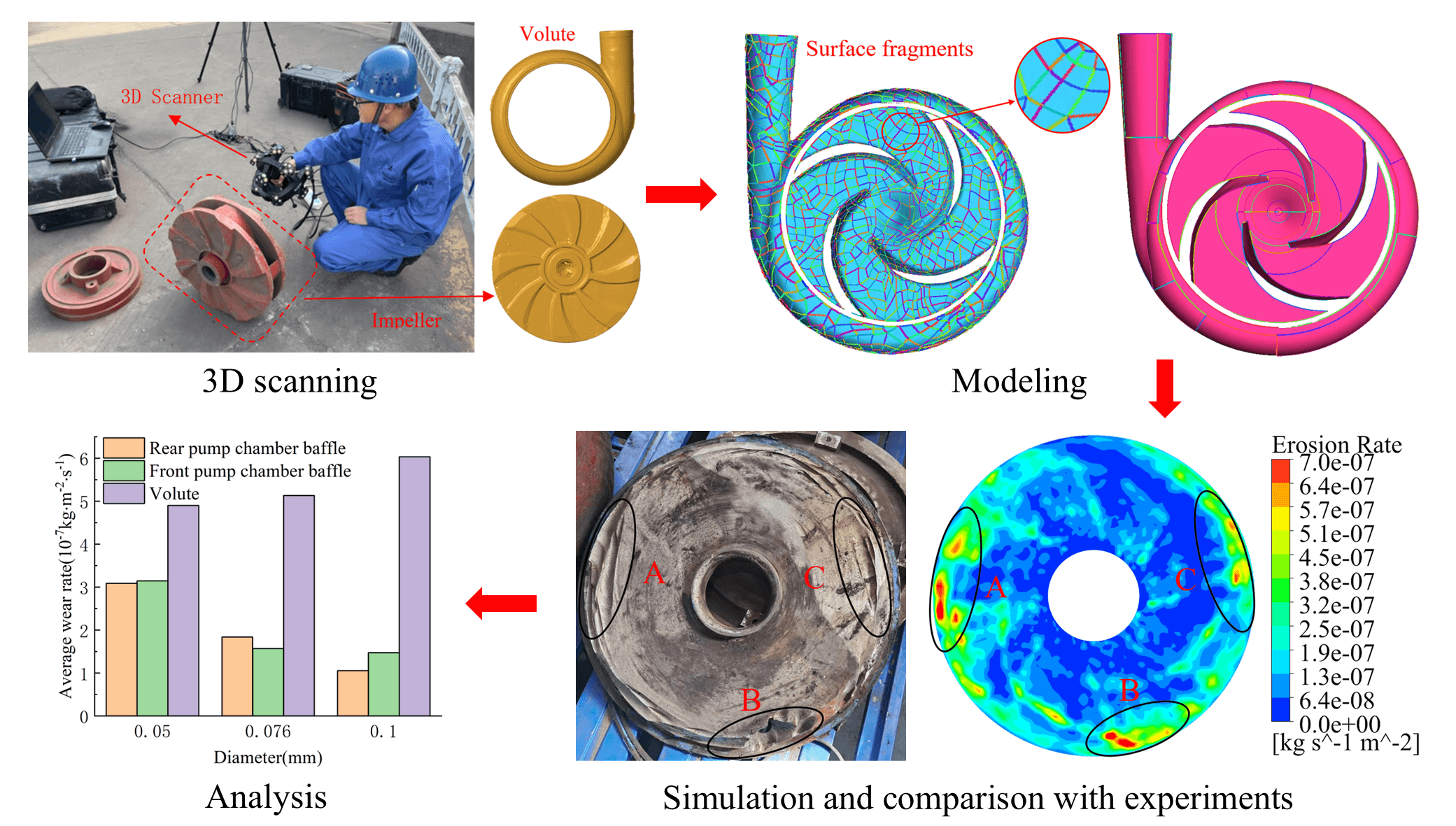
This study employed reverse modeling through optical measurement techniques to acquire and reconstruct the geometric data of the slurry pump. Additionally, the Euler-Lagrange method, combined with a generic erosion model, was utilized to conduct numerical simulations. These simulations investigated the effects of particle size and volume concentration on the erosion patterns of the slurry pump chamber baffle and volute.
2 Modeling and Numerical Calculations
2.1 Inverse Modeling of Slurry Pumps
The design parameters of the model are outlined in Table 1.
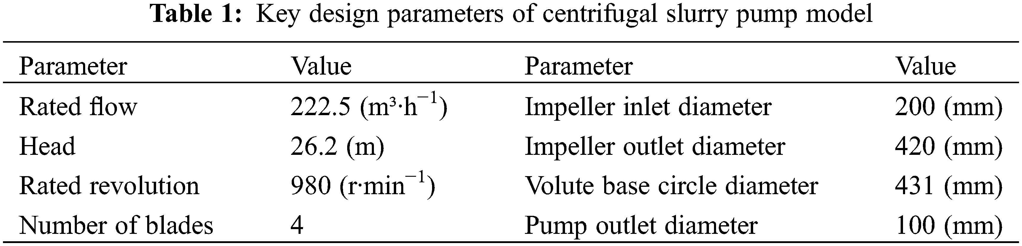
A Track Scan-Sharp 49 laser 3D scanner, with an accuracy of 0.025 mm, was utilized to capture and reconstruct the pump’s geometry. Fig. 1 illustrates the on-site scanning of the flow-through components. The process began with 3D scanning of the impeller, volute, and pump chamber baffle using a handheld device to obtain high-density spatial geometry point cloud data. This data underwent subsequent processing to eliminate outliers, noise, and extraneous information, resulting in precise 3D surface contours. Next, the spatial point cloud data was converted into a solid model to delineate the fluid domain, as shown in Fig. 2a. Finally, the fluid domains of the impeller and volute were inversely modeled to address surface fragmentation issues arising from the scanning transformation, making them suitable for CFD flow field calculations. Fig. 2b presents the fluid domain of the slurry pump model following the reverse modeling process.
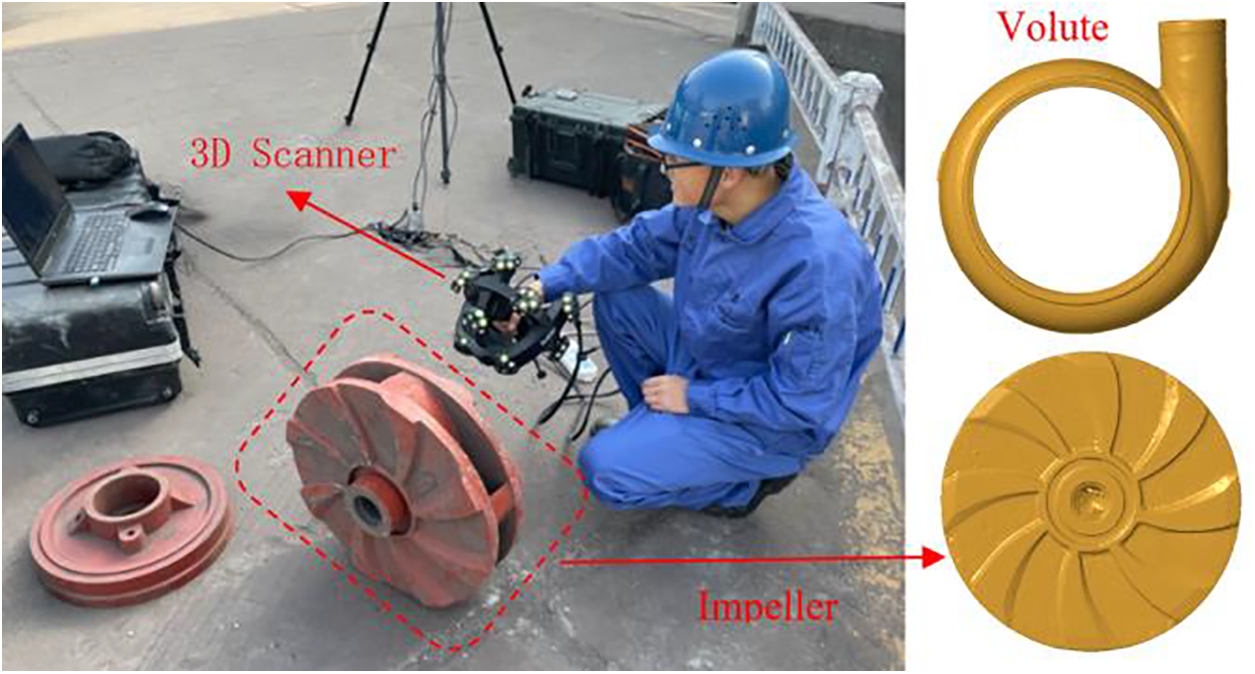
Figure 1: 3D scanning setup for high-precision geometry capture of pump components
Figure 2: Fluid domain representation of impeller and volute components
2.2 Mesh Generation and Mesh Independence Verification
The fluid domain derived from inverse modeling was discretized utilizing a hexahedral structure through ANSYS ICEM software. The mesh in the near-wall region was refined with a boundary layer to accurately capture the flow characteristics in this area. The computational domain is comprised of seven components: the inlet section, the front pump chamber baffle, the impeller front reinforcement plate, the impeller itself, the volute, the impeller rear reinforcement plate, and the rear pump chamber baffle. To satisfy the mesh quality requirements, the quality factor for each component is maintained at greater than 0.3 [22]. Fig. 3 illustrates the computational domain of the pump along with the meshing details.
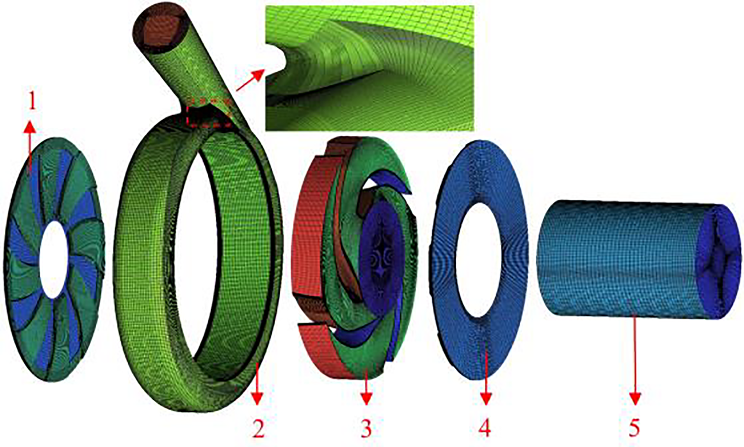
Figure 3: Computational domain and mesh structure of slurry pump components (1) Rear pump chamber baffle; (2) Volute; (3) Impeller; (4) Front pump chamber baffle; (5) Inlet section
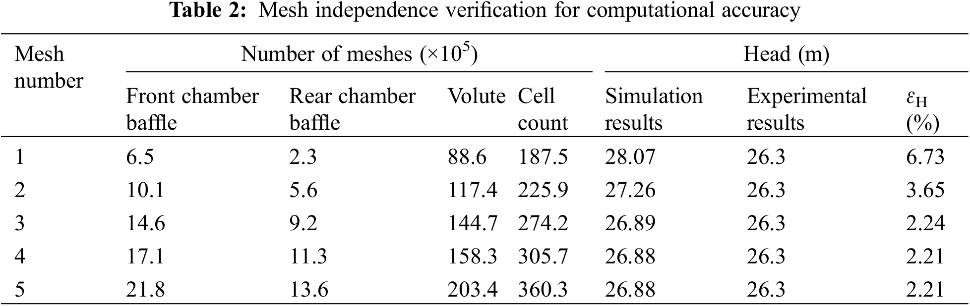
To assess the appropriateness of the employed mesh pattern, a mesh independence validation was conducted using five meshing schemes under identical operating conditions. The results of this validation are presented in Table 2. The simulation yielded a minimum head error ɛH of 2.21% compared to the experimental results when the total number of meshes reached 305.7 × 10⁵. Moreover, the error remained consistent as the number of meshes increased. Considering computational resources and efficiency [23–26], mesh 4 was selected for subsequent numerical simulations.
2.3 Numerical Calculation Settings
A steady 3D simulation was conducted to investigate the effects of gravity, assuming negligible mass transfer between the two phases. The Euler-Lagrange method was employed to analyze the solid-liquid two-phase flow within the slurry pump. The fluid phase was treated as a continuous medium governed by the Navier-Stokes equations, while the motion of solid particles was modeled as discrete phases, following Newton’s second law of motion. The solid particles were assumed to be spherical, with a density of 2650 kg/m3, and the liquid phase was characterized by a density of 998.2 kg/m3. At the inlet, the particles were assumed to have the same velocity as the fluid and were uniformly distributed across the inlet surface. The boundary conditions were established as follows: a “velocity inlet” boundary condition was applied at the pump inlet, with the velocity determined based on the pump’s flow rate, while an “outflow” boundary condition was specified for the pump outlet. To facilitate steady-state tracking, the wall boundary was designated as “reflect,” indicating that particles would rebound upon contact with the wall. Conversely, the outlet boundary was defined as “escape,” allowing particles to exit the flow field upon reaching the outlet. The impeller was modeled as a rotating domain, whereas all other domains were maintained in a stationary state. All walls were treated as no-slip boundaries. To enhance convergence, a pressure-velocity coupled algorithm was utilized, with the convergence accuracy set to 0.0001. Additionally, the monitored values of pressure and mass flow rate at the pump inlet and outlet must exhibit changes of less than 0.001% between consecutive iteration steps.
Simulation of solid-liquid two-phase flow in centrifugal pumps employed the Euler-Lagrange method. This approach incorporated multiple forces, including the drag, buoyancy, virtual mass, pressure gradient, and the Basset, Magnus, and Saffman lift forces. The primary aim of this methodology was to determine the changes in particle position and velocity within the computational domain [27–29].
The liquid phase was treated as an incompressible continuous-phase fluid, which was computed and described in motion within the Eulerian coordinate system. To account for solid-liquid interaction, an additional force
where
The governing equation of the solid phase is
where
The drag force
where
The Reynolds number of a particle can be defined as follows:
The buoyancy force
The erosion condition of the pump’s flow-through components was analyzed using the Generic erosion model available in Fluent [30,31]. This model defines the erosion rate of particles on surfaces as follows:
where
This study examined the erosion patterns within the solid-liquid two-phase flow field and overflow components under specific operational parameters, notably a particle volume concentration (Cv) of 5% and a particle diameter of 0.076 mm. The study observed the actual erosion effects on the front pump chamber baffle, rear pump chamber baffle, and volute during abnormal vibrations. A comparative analysis between the observed wear patterns and the numerical simulation results is presented in the following sections.
3.1 Erosion Characteristics of Pump Chamber
Fig. 4 presents a comparative analysis of the observed erosion condition and the simulation results for the rear pump chamber baffle. The edges of the rear pump chamber baffle exhibit distinctive circumferential grooving scratches, notably at positions A, B, and C.
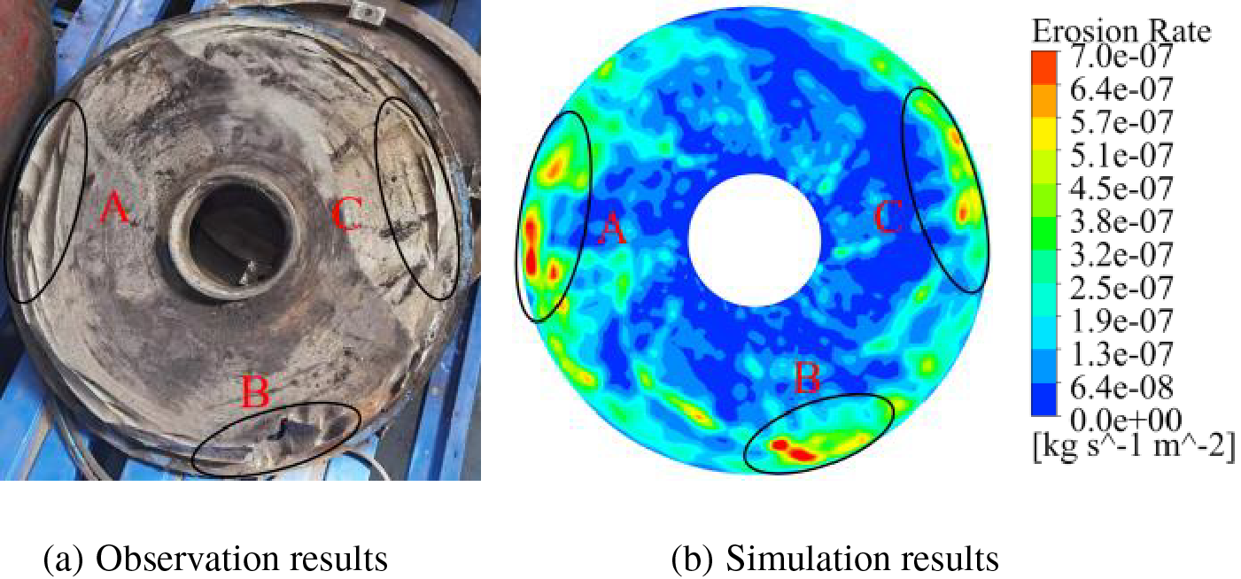
Figure 4: Comparison of numerical predictions with actual erosion on rear pump chamber baffle
During pump operation, the centrifugal force generated by the impeller propels fluid into the volute, creating a high-pressure zone. This pressure differential inevitably causes fluid leakage through the gap between the impeller and the pump chamber baffles. The leakage induces a circumferential flow due to impeller rotation, leading to particle impact and frictional wear in the rear pump chamber. At the rear chamber baffle edges, high-velocity fluid within the gap recirculates towards the volute through the clearance between the baffles and impeller, resulting in streak-like erosion along the baffle edges. As illustrated in Figs. 5 and 6, fluid within the impeller-volute clearance is particularly susceptible to extensive flow towards the initial volute section, where the pressure is lower due to the impeller’s circumferential force. This phenomenon contributes to significant erosion in zone A. Near zone B, the backflow vortex generated by SS intensifies repeated particle collisions with the rear pump chamber baffle, causing the most severe erosion (Fig. 4).
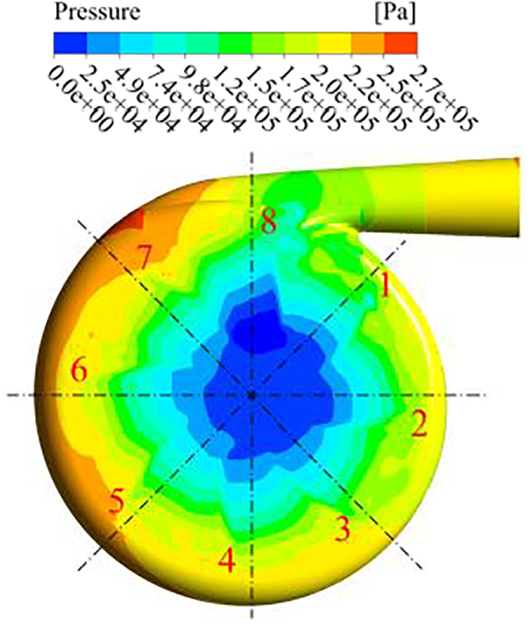
Figure 5: Rear pump chamber baffle pressure contour

Figure 6: Particle velocity and trajectory analysis at rear pump chamber baffle
Fig. 7 presents a comparative analysis of the actual erosion condition of the front pump chamber baffle alongside the simulation results. The data indicate that the erosion damage observed on the front pump chamber baffle is less severe than that on the rear pump chamber baffle (Fig. 4). The most significant damage is concentrated around the inner circumference of the baffle. Additionally, Figs. 8 and 9 illustrate the streamline and side pressure distributions for the front pump chamber baffle, respectively. As the fluid enters the gap between the volute and the impeller, it initially impacts the edge of the front pump chamber baffle. This interaction generates a substantial pressure gradient force due to the considerable pressure differential between the impeller outlet and inlet. Simultaneously, the fluid undergoes a pre-swirling effect at the impeller inlet. This phenomenon is depicted in Fig. 8, where the fluid spirals toward the impeller inlet within the gap between the pump chamber baffle and the impeller. Consequently, an arc-shaped erosion pattern extending from the edge of the front pump chamber baffle toward the impeller inlet is observed (Fig. 7).
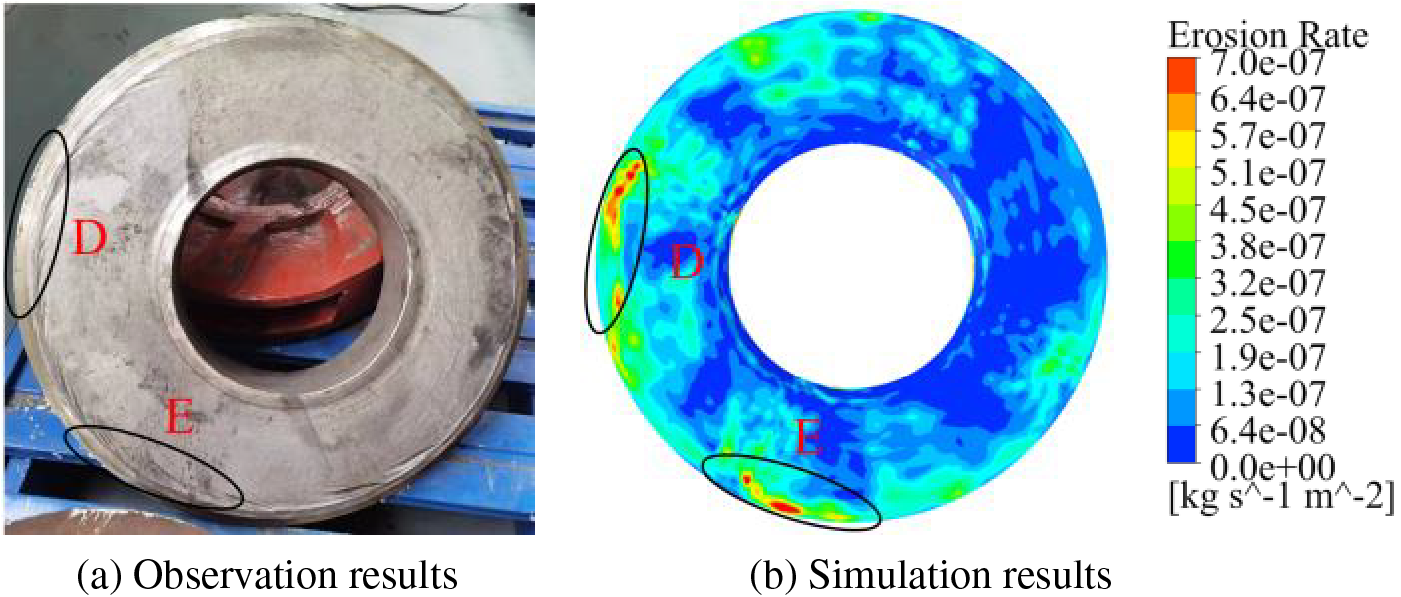
Figure 7: Comparison of numerical predictions with actual erosion on rear pump chamber baffle

Figure 8: Streamline distribution at front pump chamber baffle

Figure 9: Pressure distribution at front pump chamber baffle
3.2 Erosion Characteristics on Volute
Fig. 10 presents a comparative analysis of actual erosion and simulation results near the volute tongue. The data reveal that severe erosion on the volute is primarily concentrated on the side adjacent to the inlet, proximal to the back cover plate. This observation suggests a higher frequency of particle abrasion in this region. As particles and fluid enter the impeller at a specific velocity, the particles tend to maintain axial motion while being influenced by the impeller’s circumferential rotation. The resulting composite motion aligns more closely with the impeller’s back cover plate side, leading to increased particle collisions with the volute near the impeller’s outlet and back cover plate. This phenomenon intensifies erosion in this area. Additionally, the smaller cross-sectional area at the initial section of the volute positions its inner wall closer to the impeller’s outlet. Consequently, when particles and fluid enter the volute under the centrifugal force of the impeller, they directly impact and abrade the sidewall near the back cover plate, resulting in significant erosion at this location.
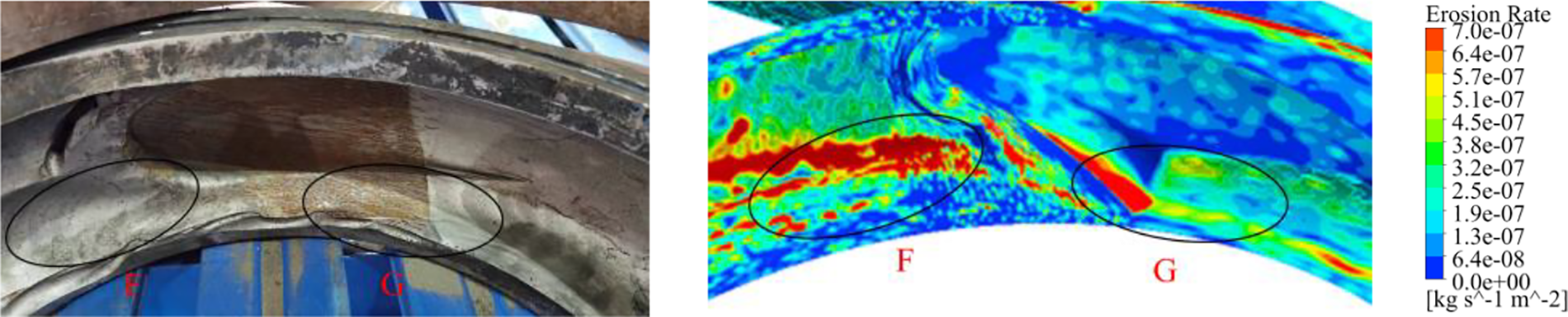
Figure 10: Comparison of actual erosion and simulation results near volute tongue region
3.3 Effect of Particle Concentration and Diameter on Erosion Characteristics
Existing literature suggested that particle concentration and size significantly influenced the erosion damage in slurry pumps [32–34]. This study examined the erosion characteristics of pump chamber baffles and volute under three particle volume concentrations: 5%, 7%, and 9%, with the particle size ranging from 0.1 to 0.05 mm.
Fig. 11 illustrates the numerical results for the average erosion rate of pump chamber baffles and the volute under various particle concentrations and diameters. The data reveal that the volute experiences the most substantial erosion damage, with an average erosion rate reaching up to 6.03 × 10⁻⁷ kg/(m2·s) when Cv is 9% and the particle diameter is 0.1 mm. For a constant Cv, the average erosion rate of the volute wall demonstrates a positive correlation with particle diameter. Moreover, under conditions of Cv = 9% and a particle diameter of 0.1 mm, the average erosion rates of the front and rear pump chamber baffles are marginally lower compared to those observed at the same particle diameter with Cv = 7%. In other scenarios, the average erosion rates of the front and rear pump chamber baffles increase as Cv rises for a fixed particle diameter. Across all conditions examined in this study, except for the scenario involving a particle diameter of 0.1 mm, the severity of erosion on the front and rear pump chamber baffles decreases as particle size increases at a constant particle concentration. Additionally, this trend of reduced average erosion rate is particularly evident when Cv is set at 9%.
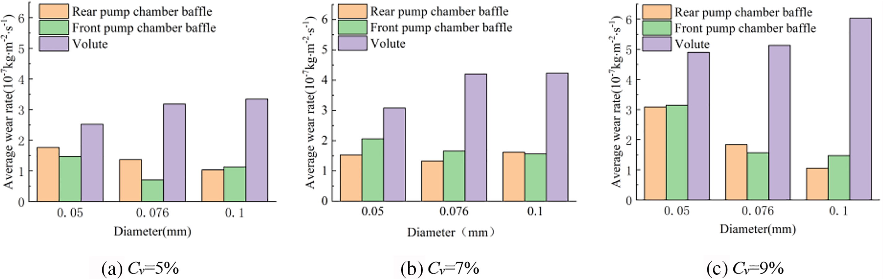
Figure 11: Average erosion rate of stationary domain surfaces with different particle concentrations and diameters
The distribution of erosion on the front and rear pump chamber baffles of the slurry pump, under varying particle concentrations and sizes, is depicted in Figs. 12 and 13. At a constant Cv, the central and peripheral regions of the front and rear pump chamber baffles exhibit varying degrees of erosion. The primary erosion areas are predominantly located at the outer edges of the pump chamber baffles. When the particle diameter is 0.05 mm, its density approximates that of water, facilitating improved fluid entrainment and increasing the probability of particles infiltrating the gap between the pump chamber baffles and the impeller. This condition results in a higher frequency of impacts and collisions with the pump chamber baffles, causing significant erosion and a widespread distribution along the outer edges of the baffles. Notably, except for the scenario where Cv = 5% and dp = 0.1 mm with localized severe erosion on the rear pump baffle, the overall erosion on the pump baffles tends to decrease as particle size increases, leading to a reduction in the erosion area across the remaining calculated cases. Furthermore, for a constant particle diameter, an increase in particle concentration from Cv = 5% to Cv = 9% results in a higher particle density within the fluid. This increase leads to a greater incidence of particles infiltrating the gap between the impeller and the baffles, significantly elevating the frequency of collisions and impacts with the pump chamber baffles. This thus intensifies the erosion on the pump chamber baffles and expands the extent of the erosion distribution.
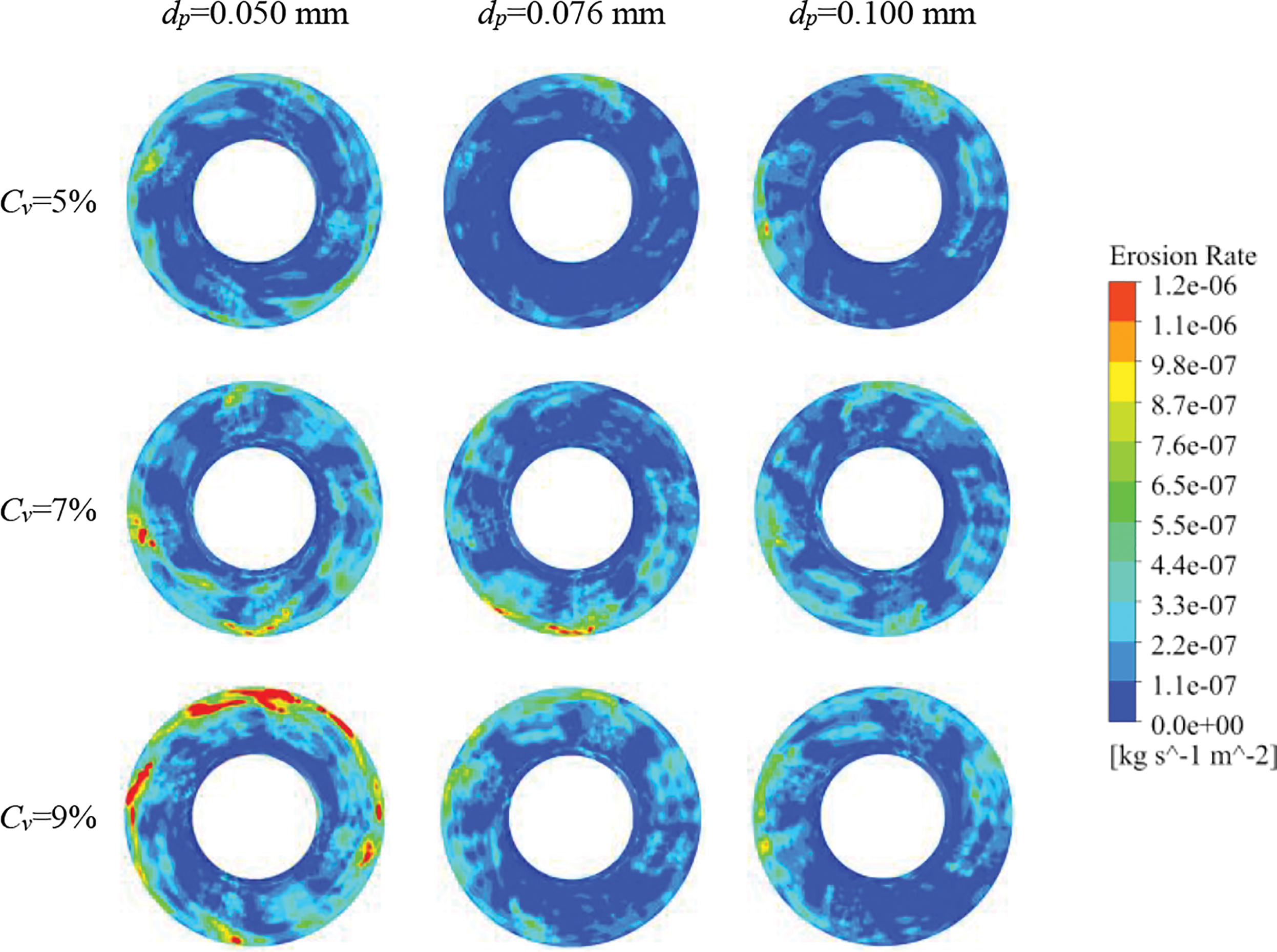
Figure 12: Erosion distribution on front pump chamber baffle under different particle diameters
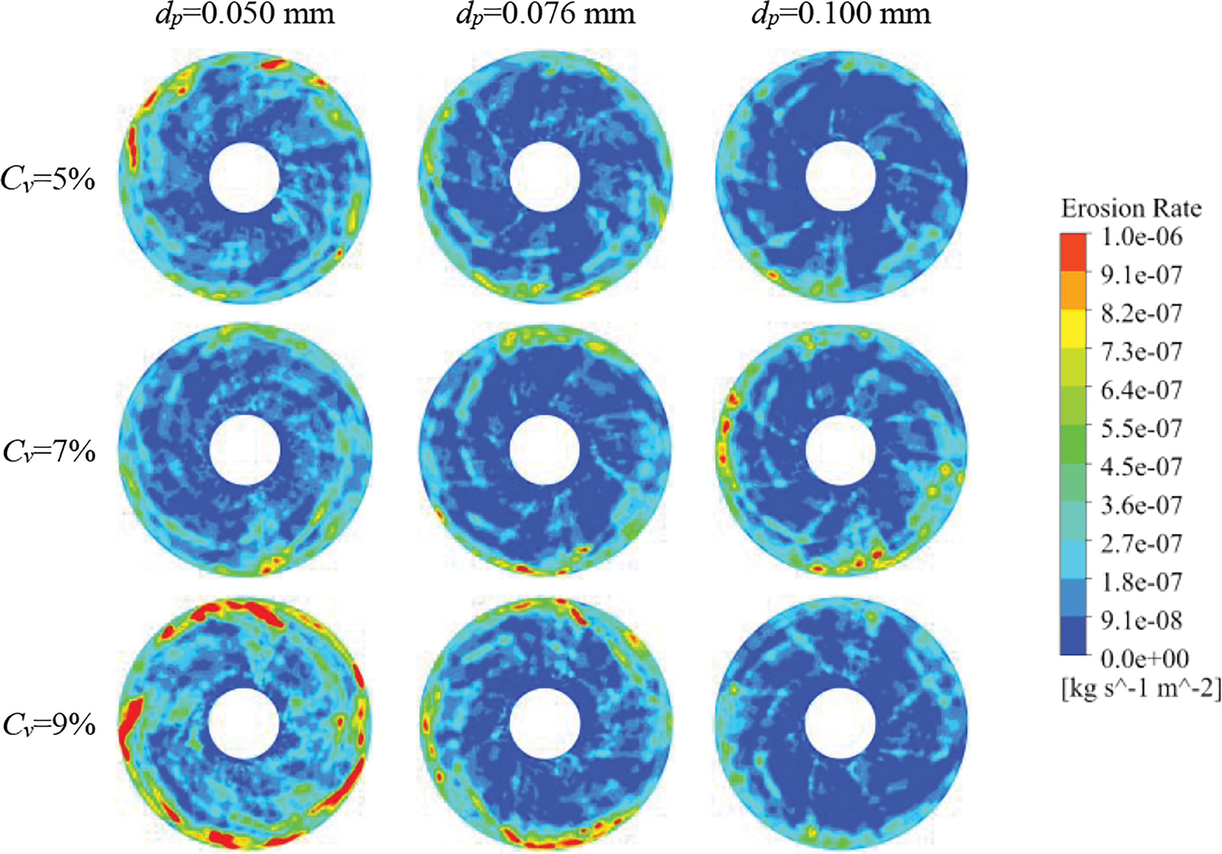
Figure 13: Erosion distribution on rear pump chamber baffle under different particle diameters
Fig. 14 illustrates the erosion distribution on the volute’s inner wall under various particle concentrations and sizes. Within the examined range of particle concentrations and sizes, the erosion damage on the volute’s inner wall shows no substantial variation across different operating conditions. However, the erosion extent at identical locations is not uniform. Specifically, at a constant Cv, the erosion distribution on the volute is more uniform when the particle size is 0.05 mm. In contrast, as the particle diameter increases to 0.1 mm, the localized erosion rate can reach up to 1.59 × 10⁻⁵ kg/(m2·s). This can be attributed to the superior fluid entrainment capability of smaller particles, resulting in lower collision energy with the volute. Consequently, the erosion distribution on the volute surface is more extensive and uniform. As particle size increases, particles gain greater kinetic energy due to centrifugal force and inertia, leading to a higher concentration of particles near the volute’s inner wall and, consequently, increased erosion on the volute surface. Furthermore, at a constant particle diameter, an increase in Cv results in a greater number of particles within the fluid, enhancing the frequency of collisions between particles and the volute wall. This, in turn, enlarges the erosion area and exacerbates the severity of localized erosion.

Figure 14: Volute erosion distribution under different particle diameters
Employing reverse modeling techniques, this study examined the erosion characteristics of slurry pump components under diverse particle inlet boundary conditions. The key findings are summarized as follows:
(1) The impeller inlet’s relative negative pressure induces an arc-shaped erosion pattern on the front pump chamber baffle, extending from its edge towards the inlet. Conversely, erosion on the rear pump chamber baffle primarily manifests at its outer edge, characterized by circumferential grooving scratches. This latter erosion pattern results from the circumferential flow generated by the rotation of the impeller back cover plate.
(2) Erosion intensity near the volute tongue is more pronounced on the back cover plate side compared to the front cover side, exhibiting a significantly higher average erosion rate than that observed on the front and rear pump chamber baffles. Under conditions of Cv = 9% and dp = 0.1 mm, the average erosion rate can reach up to 6.03 × 10⁻⁷ kg/(m2·s). The peripheral regions of the pump chamber baffle experience the most severe erosion, while wear near the baffle centers remains comparatively minimal.
(3) Increasing particle diameter while maintaining a constant volume concentration intensifies erosion near the volute tongue, expanding the erosion-affected area. Conversely, erosion on both the front and rear pump chamber baffles diminishes with larger particle sizes.
(4) Maintaining a constant particle size while increasing particle concentration results in more severe erosion and an expanded erosion area. However, the locations of erosion on the pump chamber baffles and volute remain predominantly consistent.
(5) This research offers valuable insights into erosion patterns across diverse pump flow passage components, establishing a foundation for addressing comparable engineering challenges in related domains. By incorporating real operational conditions, the findings enable precise erosion prediction in slurry pump components. This approach provides both theoretical and practical support for enhancing the safety, reliability, and service life of slurry pumps in industrial settings.
Acknowledgement: The authors would like to thank the respected reviewers for their valuable suggestions for improving the quality of the manuscript.
Funding Statement: The authors gratefully acknowledge the filnancial support of the National Natural Science Foundation of China (Grant No. 52369018), the Major Training Program of University Research and Innovation Platform of Gansu Provincial Department of Education (No. 2024CXPT-09), the Administration of Central Funds Guiding the Local Science and Technology Development, China (Grant No. 23ZYQA0320), the Double First-Class Key Program of Gansu Provincial Department of Education, Grant No. GCJ2022-38.
Author Contributions: The authors confirm contribution to the paper as follows: study conception and design: Zhengjing Shen; data collection: Yu Liu, Jilai Zeng, Wengang Yang, Jiangbo Wu; draft manuscript preparation: Fanqiang Kong. All authors reviewed the results and approved the final version of the manuscript.
Availability of Data and Materials: The internal flow field data and erosion data in this article were obtained through specific software. Data will be made available on request.
Ethics Approval: Not applicable.
Conflicts of Interest: The authors declare no conflicts of interest to report regarding the present study.
References
1. Mansour M, Kopparthy S, Thévenin D. Investigations on the effect of rotational speed on the transport of air-water two-phase flows by centrifugal pumps. Int J Heat Fluid Flow. 2022;94:108939. doi:10.1016/j.ijheatfluidflow.2022.108939. [Google Scholar] [CrossRef]
2. Huang S, Su X, Qiu G. Transient numerical simulation for solid-liquid flow in a centrifugal pump by DEM-CFD coupling. Eng Appl Comput Fluid Mech. 2015;9(1):411–8. [Google Scholar]
3. Tarodiya R, Gandhi BK. Hydraulic performance and erosive wear of centrifugal slurry pumps—A review. Powder Technol. 2017;305:27–38. doi:10.1016/j.powtec.2016.09.048. [Google Scholar] [CrossRef]
4. Walker CI, Robbie P. Comparison of some laboratory wear tests and field wear in slurry pumps. Wear. 2013;302(1–2):1026–34. [Google Scholar]
5. Kang C, Cao Q, Teng S, Liu H, Ding K. Wear characteristics of a centrifugal pump transporting solid-liquid mixture: an experimental and numerical study. Ain Shams Eng J. 2024;15(1):102277. doi:10.1016/j.asej.2023.102277. [Google Scholar] [CrossRef]
6. Gamal RH, Elyamin A, Bassily MA, Khalil KY, Gomaa MS. Effect of impeller blades number on the performance of a centrifugal pump. Alex Eng J. 2019;58(1):39–48. doi:10.1016/j.aej.2019.02.004. [Google Scholar] [CrossRef]
7. Tan M, Zhang K, Wu X, Liu H. Experimental study on large particle solid-liquid two-phase flow in a centrifugal pump. Transact Chin Soc Agricul Eng. 2021;37:62–67 (In Chinese). [Google Scholar]
8. Sangal S, Singhal MK, Saini RP. Hydro-abrasive erosion in hydro turbines: a review. Int J Green Energy. 2018;15(4):232–53. doi:10.1080/15435075.2018.1431546. [Google Scholar] [CrossRef]
9. Banka J, Rai AK. Erosion and flow visualization in centrifugal slurry pumps: a comprehensive review of recent developments and future outlook. Particulate Sci Technol. 2024;42(3):427–59. doi:10.1080/02726351.2023.2259336. [Google Scholar] [CrossRef]
10. Yin J, Yuan S, Luo Y, Shu H, Gong B. Vibration characteristics analysis for a centrifugal pump under different damage degrees of its impeller. J Vibrat Shock. 2019;38:44–49+72 (In Chinese). [Google Scholar]
11. Bandi S, Banka J, Kumar A, Rai AK. Effects of sediment properties on abrasive erosion of a centrifugal pump. Chem Eng Sci. 2023;277(6):118873. doi:10.1016/j.ces.2023.118873. [Google Scholar] [CrossRef]
12. Zhang Z, Li J, Guan T, Li Y, Zhang L. Study on optimization of sediment erosion performance for centrifugal pump impeller based on inverse design method. J Hydraul Eng. 2023;54(12):1452–36. [Google Scholar]
13. Qiao LF, Mo L, Mao LJ, Zhu L, Zeng X. Erosion wear characteristics and failure mechanism of the sulzer oil pump. J Appl Fluid Mech. 2023;17(2):424–41. [Google Scholar]
14. Wang H, Tan Z, Kuang S, Yu A. Numerical modeling and analysis of particle-fluid flow and wall erosion in centrifugal slurry pumps under different solid concentrations. Powder Technol. 2022;410:117861. doi:10.1016/j.powtec.2022.117861. [Google Scholar] [CrossRef]
15. Wang Y, Li G, Yuan X, Zhang G, Wu P, Liu HL. Influence of mixed sand on wear of centrifugal pump with semi-open impeller. J Drain Irrigat Mach Eng. 2021;39(8):764–9 (In Chinese). [Google Scholar]
16. Peng G, Huang X, Zhou L, Zhou G, Zhou H. Solid-liquid two-phase flow and wear analysis in a large-scale centrifugal slurry pump. Eng Fail Anal. 2020;114(12):104602. doi:10.1016/j.engfailanal.2020.104602. [Google Scholar] [CrossRef]
17. Shi W, Shi Y, Gao X, Zhang D, Lang T, Zhao T. Simulation and experiment on flow characteristics of large particles in vortex pump based on DEM CFD. Transact Chin Soc Agricul Mach. 2020;51(10):176–85 (In Chinese). doi:10.6041/j.issn.1000-1298.2020.10.020. [Google Scholar] [CrossRef]
18. Tarodiya R, Gandhi BK. Numerical investigation of erosive wear of a centrifugal slurry pump due to solid-liquid flow. J Tribol. 2021;143(10):101702. doi:10.1115/1.4049596. [Google Scholar] [CrossRef]
19. Noon AA, Kim MH. Erosion wear on centrifugal pump casing due to slurry flow. Wear. 2016;364–365(2010):103–11. doi:10.1016/j.wear.2016.07.005. [Google Scholar] [CrossRef]
20. Lai F, Wang F, Zhu X, Chang P, Li G. Erosion characteristics of centrifugal pumps based on E/CRC erosion model. J Harbin Eng Univ. 2021;42(5):719–28. [Google Scholar]
21. Shen Z, Chu W, Dong W. Effect of particle parameters on flow field and erosion wear characteristics of flow passage components in screw centrifugal pump. Transact Chin Soc Agricul Eng. 2018;34(6):58–66 (In Chinese). doi:10.11975/j.issn.1002-6819.2018.06.007. [Google Scholar] [CrossRef]
22. Liu B, Lu J, Feng J, Wang W, Zhu J, Ge ZG, et al. Influence of valve plate wake on the performance of centrifugal pump. Transact Chin Soc Agricul Eng. 2024;40(2):217–27 (In Chinese). doi:10.11975/j.issn.1002-6819.202308053. [Google Scholar] [CrossRef]
23. Shu X, Ren Y, Wu D, Zhu Z, Mou J. Energy loss and unsteady flow characteristics in a self-priming pump. J Hydraul Eng. 2019;50(8):1010–20 (In Chinese). [Google Scholar]
24. Tarodiya R, Gandhi BK. Numerical simulation of a centrifugal slurry pump handling solid-liquid mixture: Effect of solids on flow field and performance. Adv Powder Technol. 2019;30:2225–39. doi:10.1016/j.apt.2019.07.003. [Google Scholar] [CrossRef]
25. Zhou L, Bai L, Yang Y, Shi W, Lu W. Influence of diffuser vane number on submersible well pump performance. Transact Chin Soc Agricul Eng. 2016;47(10):78–84 (In Chinese). [Google Scholar]
26. Jafarzadeh B, Hajari A, Alishahi MM, Akbari MH. The flow simulation of a low-specific-speed high-speed centrifugal pump. Appl Math Model. 2011;35(1):242–9. doi:10.1016/j.apm.2010.05.021. [Google Scholar] [CrossRef]
27. Shen Z, Chu W, Li X, Dong W. Sediment erosion in the impeller of a double-suction centrifugal pump—A case study of the Jingtai Yellow River Irrigation Project, China. Wear. 2019;422–423(10):269–79. doi:10.1016/j.wear.2019.01.088. [Google Scholar] [CrossRef]
28. Wang K, Liu H, Wang L, Lu J. Effects of particle volume concentration on the leakage vortex and erosion characteristics of semi-open centrifugal pumps. Transact Chin Soc Agricul Eng. 2023;39(16):44–53. [Google Scholar]
29. Qi D, Song X, Shen Y, Zou X, Du L, Wang Z, et al. Numerical simulation and prediction of flow characteristics and wear in the impeller of a centrifugal pump. China Rur Wat Hydrop. 2023;(1):134–8+151. [Google Scholar]
30. Zhang Z, Li Y, Chen D. Investigation on unsteady erosion characteristics in impeller of double suction centrifugal pump. Transact Chin Soc Agricul Mach. 2022;53:140–8,191 (In Chinese). [Google Scholar]
31. Dong J, Qian Z, Thapa BS, Thapa B, Guo Z. Alternative design of double-suction centrifugal pump to reduce the effects of silt erosion. Energies. 2019;12(1):158. doi:10.3390/en12010158. [Google Scholar] [CrossRef]
32. Nguyen VB, Nguyen QB, Zhang YW, Lim CYH, Khoo BC. Effect of particle size on erosion characteristics. Wear. 2016;348–349(3):126–37. doi:10.1016/j.wear.2015.12.003. [Google Scholar] [CrossRef]
33. Haider G, Othayq M, Zhang J, Vieira RE, Shirazi S. A effect of particle size on erosion measurements and predictions in annular flow for an elbow. Wear. 2021;476(2):203579. doi:10.1016/j.wear.2020.203579. [Google Scholar] [CrossRef]
34. Uzi A, Levy A. On the relationship between erosion, energy dissipation and particle size. Wear. 2019;428–429(8):404–16. doi:10.1016/j.wear.2019.04.006. [Google Scholar] [CrossRef]
Cite This Article
 Copyright © 2025 The Author(s). Published by Tech Science Press.
This work is licensed under a Creative Commons Attribution 4.0 International License , which permits unrestricted use, distribution, and reproduction in any medium, provided the original work is properly cited.
 Downloads
 Citation Tools