
 Submit a Paper
 Propose a Special lssue
 Open Access
ARTICLE

Blade Cutting Influence on Centrifugal Pump Noise Reduction
1 Beijing Haiji Jiasheng Technology Co., Ltd., Beijing, 101300, China
2 Hanjiang Hydropower development Co., Ltd., Shiyan, 442000, China
3 Department of Mechanics and Engineering Science, College of Civil Engineering and Mechanics, Lanzhou University, Lanzhou, 730000, China
* Corresponding Author: Tianpeng Li. Email:
Fluid Dynamics & Materials Processing 2025, 21(3), 623-644. https://doi.org/10.32604/fdmp.2024.053862
Received 12 May 2024; Accepted 20 November 2024; Issue published 01 April 2025
 View Full Text
 Download PDF
Abstract
A centrifugal pump with a specific speed ns = 67 is considered in this study to investigate the impact of blade cutting (at the outlet edge) on the fluid-induced noise, while keeping all the other geometric parameters unchanged. The required unsteady numerical calculations are conducted by applying the RNG k-ε turbulence model with the volute dipole being used as the sound source. The results indicate that the internal pressure energy of the centrifugal pump essentially depends on the blade passing frequency and its low-frequency harmonic frequency. Moreover, the pressure pulsation distribution directly affects the noise caused by the centrifugal pump. The sound pressure inside and outside the centrifugal pump and the sound power at the blade passing frequency gradually decrease increasing cutting distance of the impeller blades. When the cutting percentage is 1.21%, that is, the clearance ratio between impeller blade and tongue is 8.57%, the comprehensive performance of the centrifugal pump is the best.Keywords
As a general machinery, centrifugal pump is broadly applied in national defense, military, industrial manufacture, and civilian fields. The research and optimization of high-performance equipment are closely related to national strategic security and the development of the national economy [1]. With the increasingly strict environmental standards and continuous improvement of customers’ requirements, the noise of centrifugal pumps has gradually become a key factor for ordinary industrial or civil equipment, and the noise mainly comes from two aspects: radiated noise resulting from mechanical vibration and fluid excitation [2]. Nowadays, mechanical noise can be effectively reduced through anti-vibration technology and vibration isolation materials. However, the flow-induced noise is relatively complex and accounts for a large proportion. For equipment that is running stably, flow-induced noise is a crucial factor affecting equipment noise pollution. It is generally believed that the complex vortices and strong, unsteady effects in the flow field are the main causes of noise generation [3,4]. For example, the gap vortex [5], the periodic shedding vortex at the tail of the blade, and the dynamic-static interference effect [6] are the main factors affecting the generation of noise. The dynamic-static interference between the flow-passing components will not only cause the flow field to be turbulent but also bring about the generation of noise [7]. The generation of flow-induced noise can impact the stable operation of the pump itself, and reduces the comfort of work [8]. Therefore, high-efficiency and low-noise impeller rotating machinery has gradually become a hot topic [9].
The noise that appeared in the operation of the centrifugal pump is an important criterion to judge its performance. Some researchers have done a great deal of research on the internal flow excitation noise of centrifugal pumps [10]. The developments of Arbey and others are widely used to explain the discrete vibration and noise caused by trailing edge vortex shedding [11,12]. “The noise reduction theoretical model of blade saw-tooth trailing edge” proposed by Howe is widely used in blade turbulent boundary noise [13]. The research results of many scholars show that the hydrodynamic noise of centrifugal pump is mainly associated with the dynamic-static interference between the impeller and volute [14–18], and the main research direction is to reduce the noise of intense pressure pulsation caused by such interference by changing geometric parameters. Cheng et al. [19] used a special blade cutting method to study the noise of centrifugal pump. Guo et al. [20] investigated the impact of the number of blades on flow-induced noise, the findings indicated that centrifugal pumps with an even number of blades have superior acoustic performance. Wei et al. [21] analyzed the noise performance of centrifugal pump by staggering the rotor and stator to form an X-shape. Jia et al. [22] studied the influence of different volute area ratios on internal flow characteristic and noise inside the pump; the results showed that a proper volute area ratio can obviously improve the turbulence inside the pump, thereby reducing pressure pulsation and achieving noise reduction.
Although many literatures have studied the fluid-induced noise by experiment or calculation, there is little in-depth study on the noise in low specific speed centrifugal pumps. Because the impeller passage of low specific speed centrifugal pump is elongated and narrow, which easily leads to the separation of the internal flow field, secondary flow and “jet-wake”, and the research on its pressure pulsation and noise characteristics are scarce, especially the development law of noise reduction in low specific speed centrifugal pump is still lacking. In the present research, a centrifugal pump with a specific speed of 67 is taken as the original model, and RNG k-ε turbulence model and boundary element method are adopted to determine the internal field noise. Additionally, the finite element method coupled with the acoustic boundary element method is adopted to analyze the external field noise, and then its flow field and internal sound field are verified by experiments. Finally, the performance characteristics of centrifugal pumps under various cutting schemes are researched, which provides some theoretical support for further noise reduction.
2 Theory of Numerical Computation
The basic governing equation of fluid motion is Navier-Stokes equation. The continuity equation and momentum equation of incompressible fluid are, respectively [23]:
where, ρ is the density of incompressible fluid; t presents time; p refers to pressure exerted on the fluid; ui is the velocity component; xi is the Cartesian coordinate system;
According to the above equation, after the governing equation is treated with time average, the pulsation velocity term is added to the governing equation to reflect the influence of the pulsation velocity on the average motion (Reynolds stress). Nevertheless, for the increase of Reynolds stress, the governing equation is not closed. Hence, it should establish the association between Reynolds stress and the average motion, that is the so-called turbulence model. In this study, the RNG k-ε turbulence model is mainly used, and its expressions are Eqs. (3) and (4) [24]:
where,
Because of the great difference between the flow scale and the sound scale, it is hard to use the fluid-sound coupling to solve the flow-induced noise of the pump directly. Generally, the acoustic analogy method is used to characterize the sound source in the pump. The acoustic analogy method is first proposed by Lighthill, it is assumed that the sound source exists independently in the flow field, and the sound wave is not interfered by the fluid, the sound radiation equation of the moving fluid is deduced according to the N-S equation. Curl uses the Gilhoff method to consider the effect of solid obstructed surfaces in the fluid. Ffowcs Williams and Hawkings extend the result of Curl to the boundary of moving solid and put forward FW-H equation [25]:
where, ρ0 is fluid density without disturbance; p0 is pressure exerted on the fluid without disturbance; c0 is the sound speed; Tij = ρuiuj + (p’ − c2 0ρ‘)−τij is called the Lighthill stress tensor; τij is the viscosity tensor.
In the actual calculation of fluid, it is often necessary to further simplify. Because of the characteristics of high Reynolds number and low Mach number of the flow in the pump, it can be considered that the influence of monopole and quadrupole in the flow field is small and can be ignored. Taking the dipole sound source as the main noise source, the centrifugal pump is mainly formed by the pressure fluctuation on the volute surface and blade surface, from which the dipole sound source on the volute surface and blade surface is extracted, the sound pressure in the far field can be approximately expressed as:
In the formula, r represents the position vector of the source point; Pij represents the fluid pressure on the boundary and constitutes the surface dipole source.
The time domain fluctuation of the pressure on the volute surface and blade surface is obtained by CFD, and it is introduced into the volute surface and blade surface of internal acoustic model. The frequency-domain pressure fluctuation is obtained by Fourier transform, that is, the intensity of dipole sound source on volute surface and blade surface is obtained. Fig. 1 is the flow chart of the centrifugal pump.
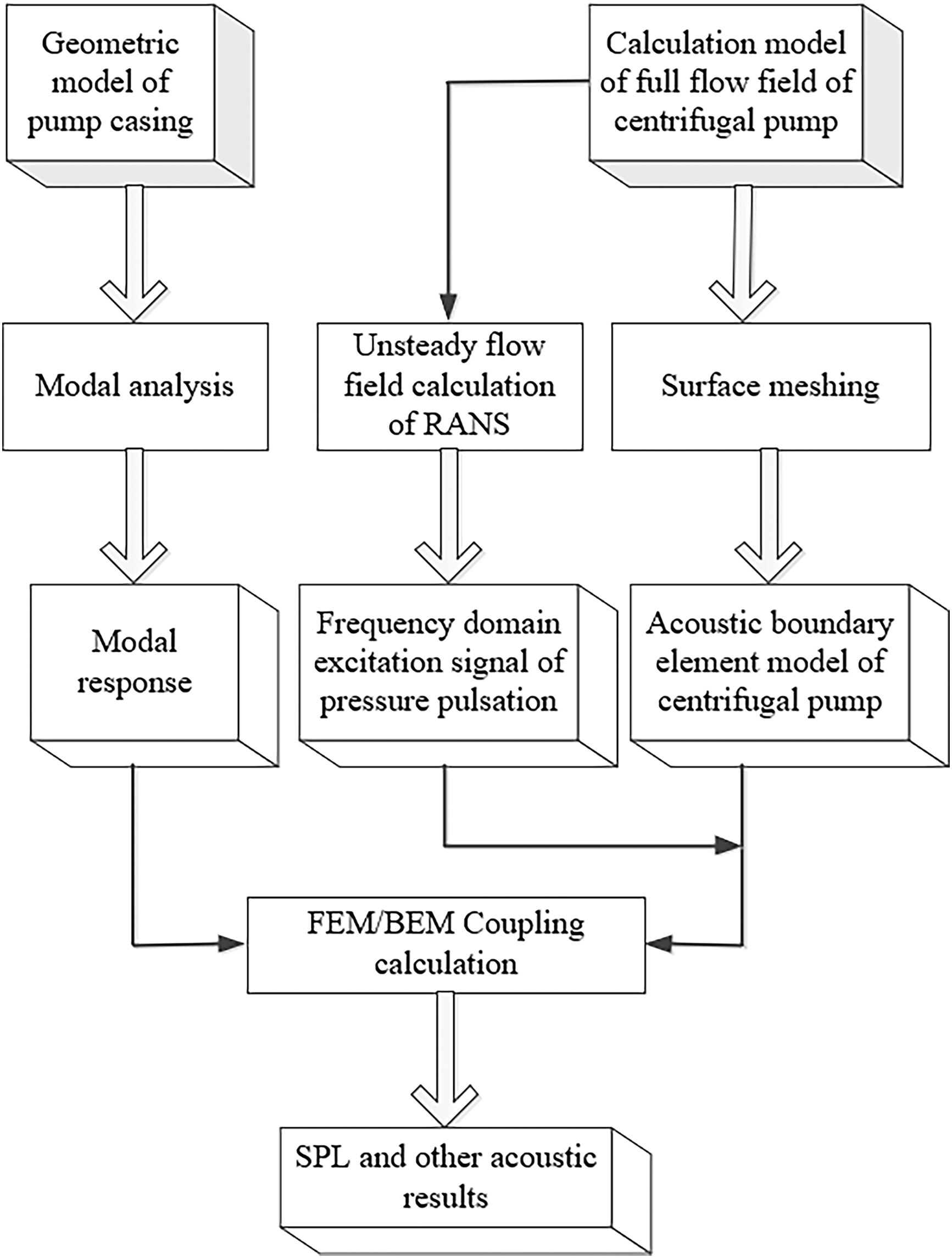
Figure 1: Flow chart
3 Computational Model and Simulation Analysis Method
In present research, a centrifugal pump with specific speed of 67
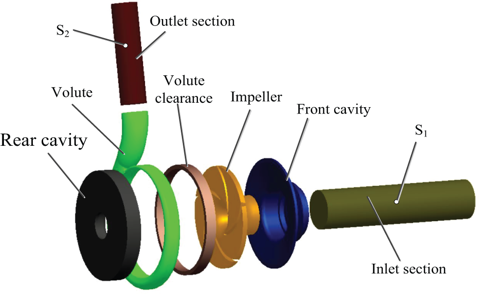
Figure 2: Computational fluid domain model
When designing a centrifugal pump, it is necessary to choose the appropriate clearance between impeller and tongue. The smaller clearance will cause greater dynamic-static interference, resulting in larger vibration and noise. Although the larger clearance can reduce the non-uniformity of the impeller outlet flow, when the clearance is too larger, because of the rotational liquid circulations at the clearance, it will consume energy, thus reducing the head and efficiency of the pump and narrowing the high-efficiency zone of the pump [26].
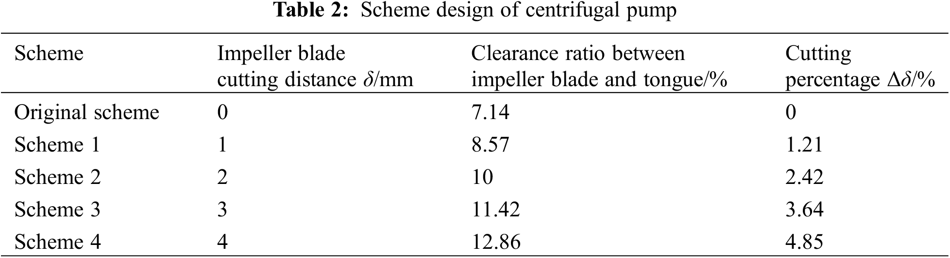
The cutting method of traditional impeller can lessen the effect of dynamic-static interference by increasing the clearance between the impeller and the volute tongue appropriately and then reducing the flow-induced noise of the centrifugal pump, but at the cost of changing the hydraulic performance of the pump. Therefore, this study will retain the front and rear cavity and only cut the impeller blade outlet for research so as to study the impact of the change of clearance between the impeller blade and the volute tongue on the performance and flow-induced noise of the model pump. This cutting method can effectively control the backflow at the impeller outlet, and reduce the trend of backflow in the outlet area, making the outlet flow tend to be uniform and enhancing the working stability of the pump. Research shows that the head of only cutting the blade without cutting the cavity is nearly 5% higher than that of cutting the cavity and blade at the same time [27], however it also brings some disadvantages, for example, this method requires a very precise cutting technology, and the manufacturing cost is relatively higher. The scheme of blade cutting is shown in the Fig. 3, δ is cutting distance, b2 is the outlet width of blade, D2 is outlet diameter of impeller, and the cutting percentage Δδ is defined as the ratio of the cutting distance δ at the blade outlet to the outlet diameter D2 of the impeller, that is, Δδ = 2δ/D2 × 100%, the specific cutting scheme is shown in Table 2.
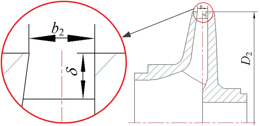
Figure 3: Schematic diagram of blade outlet cutting
3.3 Theoretical Analysis of Cutting Scheme
Fig. 4 shows velocity triangle diagram at the impeller outlet, and the relationship between the three velocities are as follows:
where,
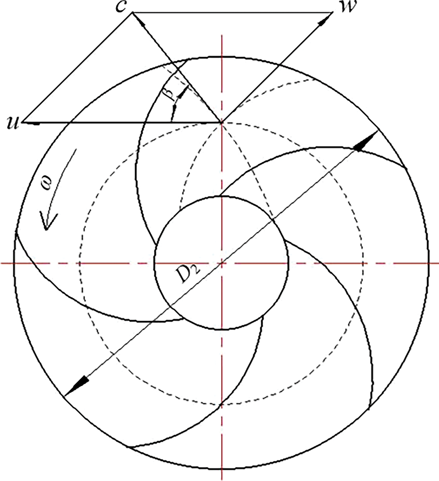
Figure 4: Velocity triangle at the impeller outlet
When cutting the outlet edge of blade, the outlet diameter of the blade is decreasing, which results in a decrease in circumferential velocity according to the Eqs. (7) and (8). In accordance with conservation of energy, part of the kinetic energy caused by the rotation of the impeller will be transformed into pressure energy, and the kinetic energy will gradually decrease with the increase of cutting distance. According to theoretical analysis, the head performance of the centrifugal pump will decrease when the cutting distance increases gradually. Therefore, it is very necessary to weaken the noise when cutting the blade outlet edge without sacrificing the head performance of the centrifugal pump.
3.4 Grid Generation and Independence Verification
Due to the complex structure of the centrifugal pump, and there are literatures showing that the use of unstructured grid and the selection of the RNG k-ε turbulence model can also predict the changes of the flow field and sound field in the pump, this study will use this method to calculate the subsequent flow field [28–30]. Unstructured grid is divided in the present research, and the regional grid with complex structure is locally encrypted, that is, the leading edge of the impeller blade and the volute tongue are encrypted as necessary. The grid generation is shown in Fig. 5a. Because the RNG k-ε turbulence model adopts the wall function method, the selection of the y+ value is also related to the Reynolds number; therefore, for the flow of low Reynolds number inside the centrifugal pump, the surface y+ value should be kept within 300 as much as possible. The surface y+ value of the impeller blade is exhibited in Fig. 5b. It is concluded that the y+ values on the surface of the impeller blades are mainly concentrated between 50~150, which fully meets effect of the RNG k-ε turbulence model on the quality of grid. It can be used for grid independence verification in the future, as shown in Fig. 5c, when the grid number increases, the head is also increasing, when the grid number increased to a certain number, the range of head variation is within 1%, so the total grid number is decided to be 2.6673 × 10⁶.
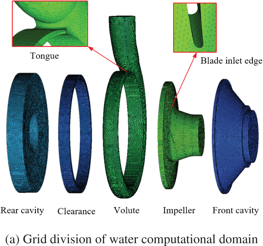
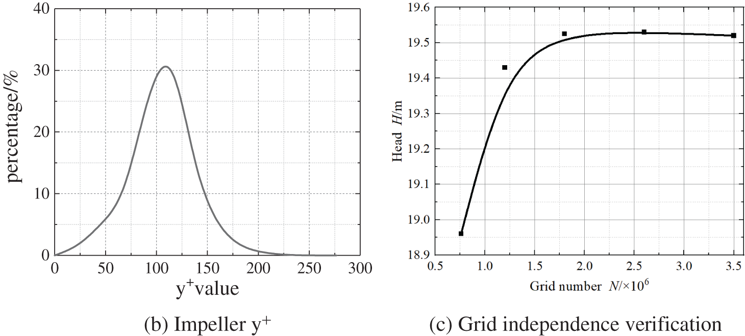
Figure 5: Computational model of fluid domain
3.5 Setting of Boundary Condition and Transient Time Step Verification
In the present research, RNG k-ε turbulence model is adopted, the inlet boundary is set as the pressure inlet, the outlet boundary is set as the mass flow outlet, the impeller as the rotating domain, other components as the stationary domain, and the solid wall surface as the non-slip boundary condition. The turbulent viscosity term is calculated by the high-precision second-order scheme, and the SIMPLE algorithm is applied for steady calculation with a convergence accuracy of 10−5. After that, the transient calculation is performed.
In transient calculation, the time step should be verified firstly [31]. Generally, the smaller the time step, the higher the precision of the calculation result. However, under this condition, the more time and memory of the computer will be occupied, which will greatly waste computing resources. Therefore, it is very necessary to select a reasonable time step. In this study, the time steps are verified under the design condition, and the corresponding time steps are 5.747 × 10⁻⁵ s, 1.149 × 10⁻⁴ s, 1.724 × 10⁻⁴ s, 2.299 × 10⁻⁴ s and 2.874 × 10⁻⁴ s when the impeller rotates 1°, 2°, 3°, 4°, 5°and 6°, respectively. Fig. 6 exhibits the changes of the instantaneous head under different time steps; the trends of the instantaneous head are generally consistent. With decreases in the time step, the fluctuation of the instantaneous head is also decreasing. Considering the influence of computing resources and time, this study uses the impeller rotation of 3° as a time step to calculate the transient flow field.
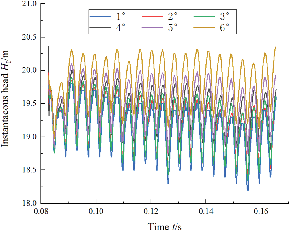
Figure 6: Time step verification
Wang et al. [32] analyzed the internal sound field information of the blade rotating dipole and volute fixed dipole sound sources obtained by calculating the unsteady flow field, the results showed that the volute fixed dipole sound source had a greater influence on the noise of centrifugal pump than the blade rotating dipole sound source. Therefore, the volute dipole boundary condition can be used as the acoustic boundary condition, the inlet and outlet of the centrifugal pump can be set as the full sound absorption property, and the direct boundary element method is used for calculation to obtain the response solution on the boundary element. The boundary condition of the volute dipole excited internal field noise is shown in Fig. 7.
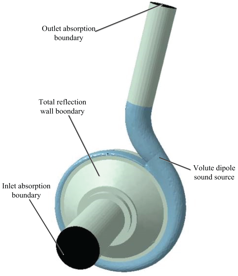
Figure 7: Boundary conditions of volute dipole sound source
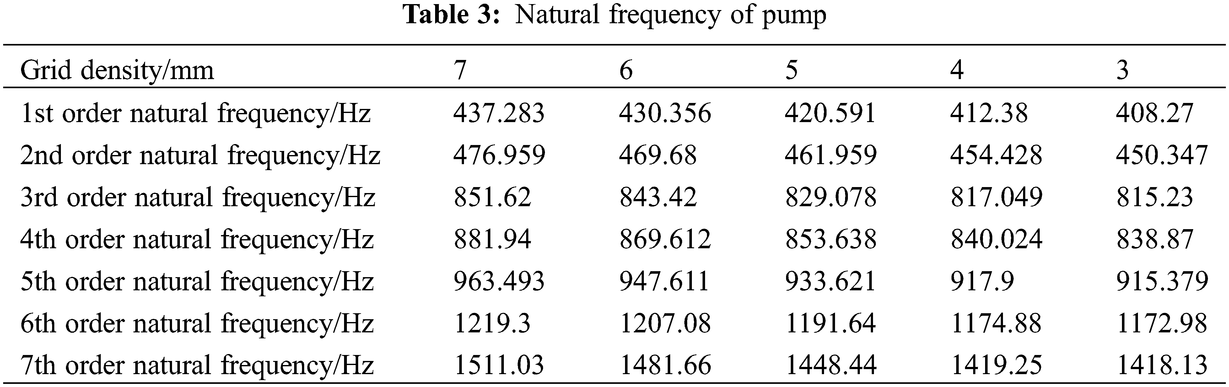
Vibration is an inherent characteristic of elastic structure, and modal analysis is often used to evaluate the vibration characteristic of the structure. In this study, the material of the pump body is cast iron, the elastic modulus E = 200 Gpa, the density ρ = 7800 Kg/m3, and the Poisson’s ratio μ = 0.3. When modeling the centrifugal pump body, the small hole bolt and other parts are not considered, only the main part of the pump body is considered, and the final mesh division is shown in Fig. 8. Taking into consideration that the number of grids will influence the precision of the results, the solid domain grid is verified. The verification results are shown in Table 3, as the grid density decreases, the front seven-order natural frequency is continuously decreasing. When the grid density is 4 mm, if grid density continues to decrease, it is found that the relative errors of the first seven-order natural frequency all are within 1%, so this study uses a grid density of 4 mm and finally determines the number of solid domain grids to be 3.168 × 10⁶.
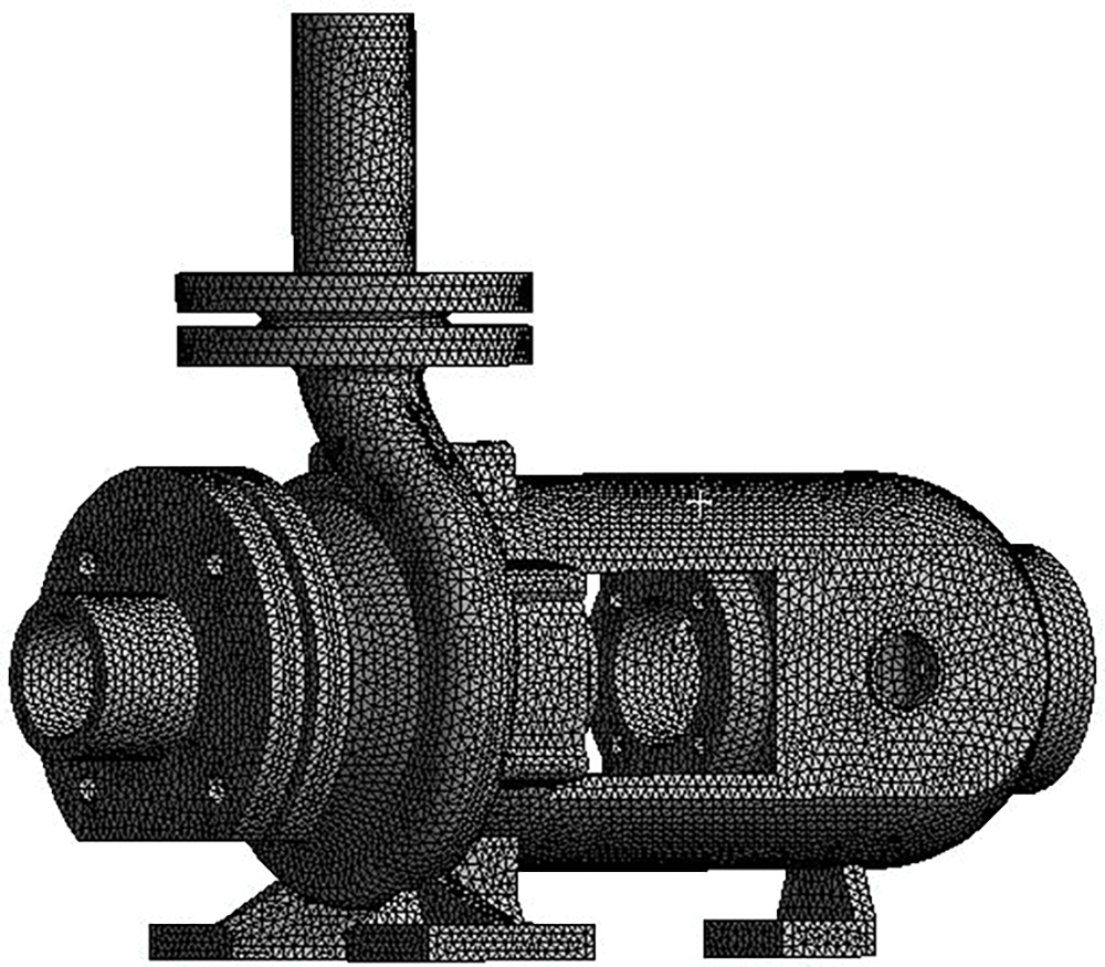
Figure 8: Solid domain grid
The natural frequencies of the front seven order modes of centrifugal pump are exhibited in Fig. 9, It can be obtained from figure that the realization of centrifugal pump body mainly occurs in the inlet and outlet areas, especially in the outlet area. It is inferred from the first mode that the pump body swings left and right, while the second mode swings back and forth. Considering the first seven modes, the most obvious deformation area of pump body is at the outlet connection of pump body, and at the same time, the joints of various components are also obvious deformation areas, because the alternating stress easily generated in the connection areas of components.
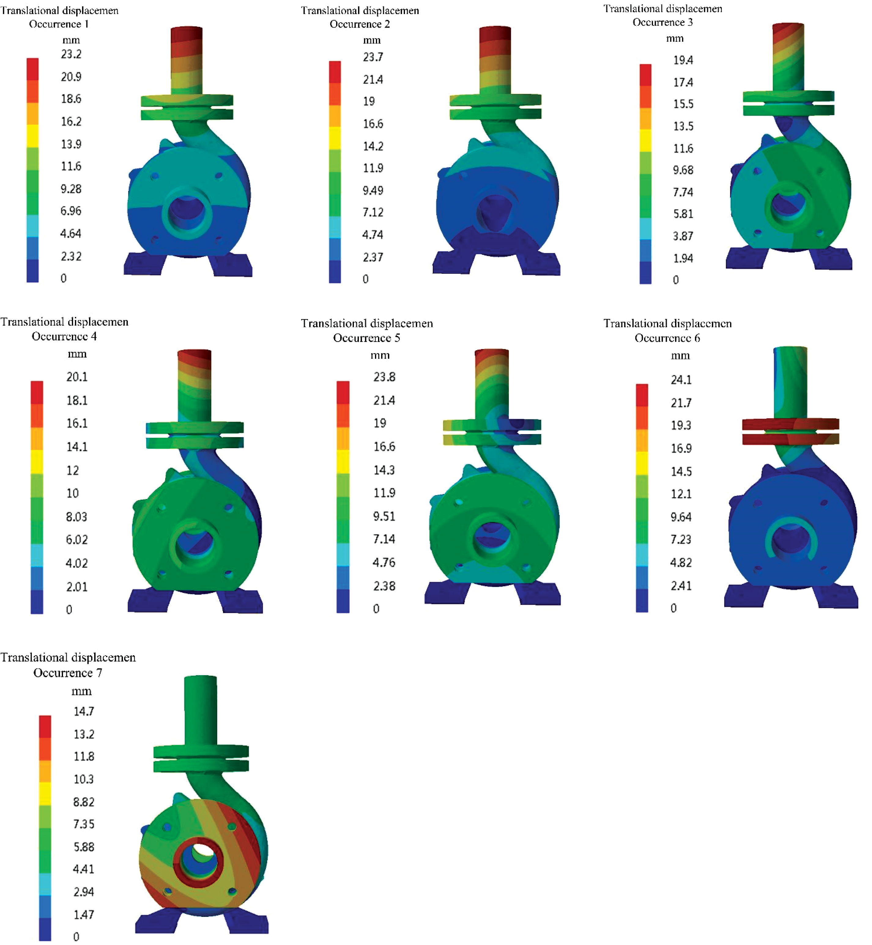
Figure 9: Modal anysis of centrifugal pump body
To ensure the feasibility of the flow field calculation and sound field calculation, the experimental setup constructed is exhibited in Fig. 10. The physical model of the impeller used in this experiment is exhibited in Fig. 11. The specific specifications and parameters of the instrument are exhibited in Table 4.
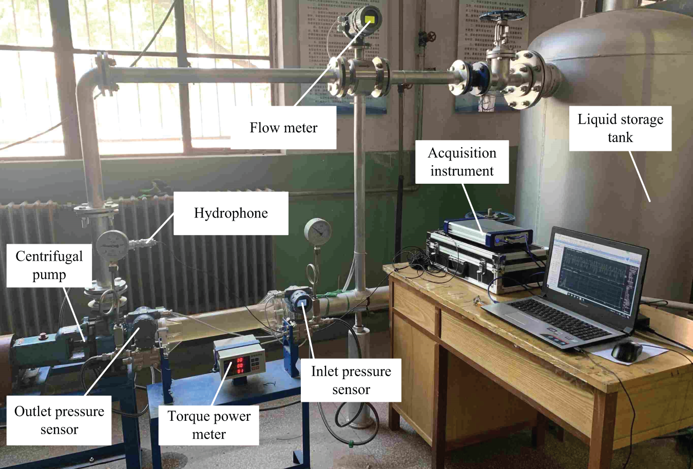
Figure 10: Experiment apparatus
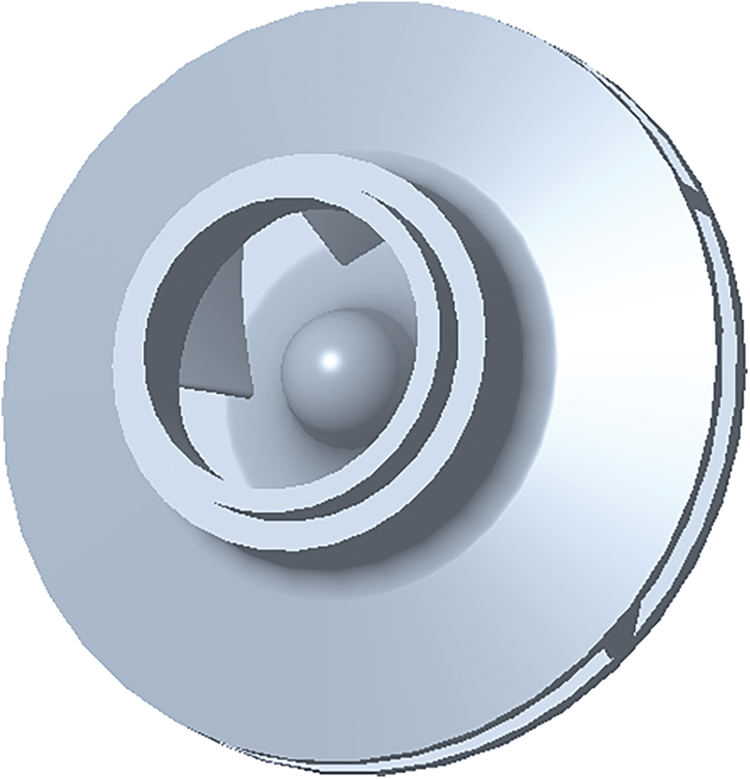
Figure 11: The physical model of the impeller
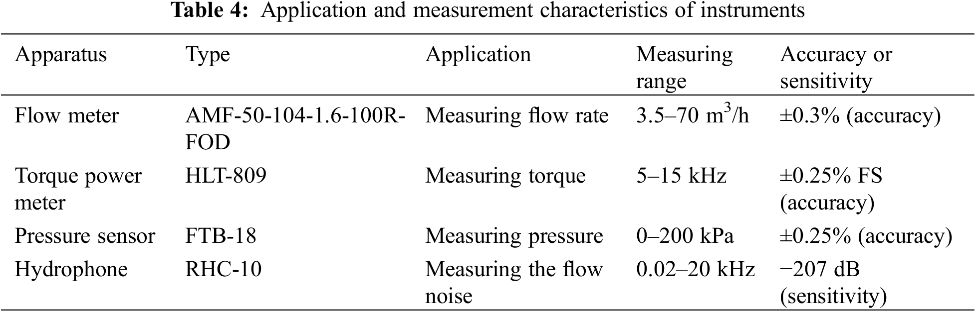
Fig. 12 shows the results of external characteristics for calculation and test; according to the figure that, the trends of head and efficiency determined by the calculation and test are basically consistent, and the head varies greatly under small flow rates, and the relative error between them is the largest, reaching 4.7% at the flow rate of 0.6 Qd, because the flow is extremely unstable, resulting in slight vibration. The relative error of the efficiency under the design flow rate is 2.3%; under the non-design flow rates, the relative error is 5%, which is larger compared to the design flow rate. In a word, the turbulence model used in this study is true and reliable and has certain accuracy in the subsequent flow field calculation.
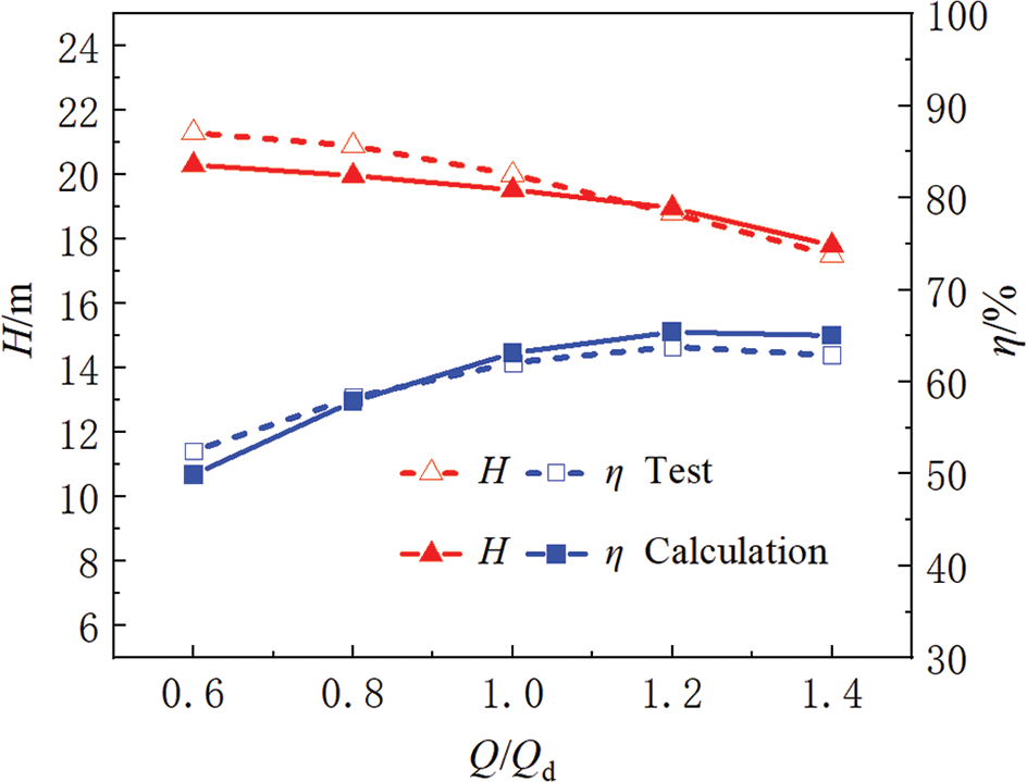
Figure 12: Calculation and test results of external characteristics
Because the external field noise of the centrifugal pump is caused by the rotation of motor, vibration of the pump body, pipeline and environment, these external noises are inevitable, and the external field noise affects the internal field noise. In order to make the difference between the experimental noise and the calculated noise as small as possible, the inlet and outlet liquid storage tanks are filled with water to prevent noise caused by turbulent water inside the tanks, at the same time, starting the motor while disconnecting it from the pump, the sound pressure value measured by the outlet hydrophone of the centrifugal pump is much lower compared to the noise measured at the outlet when the pump is working normally. Therefore, the noise detected at the outlet is mainly due to the noise caused by the pump when it is working. In order to prevent interference from other noise, the test is carried out at night, and other equipment is not working during the test.
Fig. 13 shows the results of the internal sound field for numerical calculation and test; the calculated values of sound pressure level within 2000 Hz are less than the experimental values, and the coincidence degree between them is higher in the low-frequency band. At the blade passing frequency and its frequency doubling, the maximum sound pressure level appears at the blade passing frequency, the relative error between the calculated value and the tested value is 9.5%, the relative error at two blade passing frequency is 6.3%, and the maximum relative error at three blade passing frequency is 9.7%. Because the maximum error is within the allowable range, it is feasible to determine the noise of the centrifugal pump through this method. This error can be explained that the effects of the internal flow field (cavitation, backflow, etc.), external field noise and pipeline resonance are not taken into account when calculating the internal sound field noise.
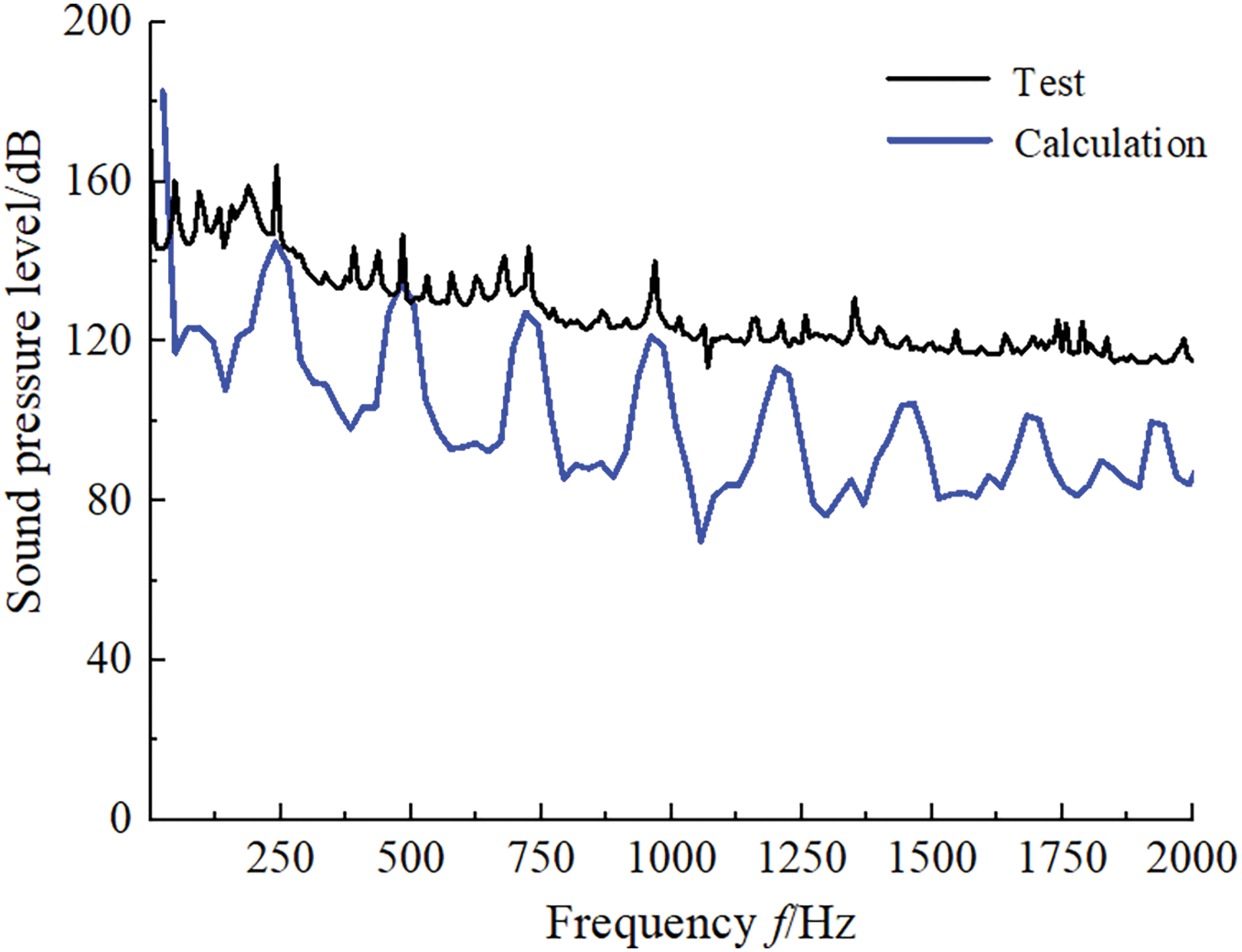
Figure 13: Calculation and test results of internal sound field
6.1 The Performance of Centrifugal Pump
Fig. 14 shows the performance curves of centrifugal pump under different schemes. The trends of numerical calculation results under different schemes are basically consistent, but with the increase of cutting amount, the head loss is the largest under scheme 4 (cutting distance is 4 mm). As shown in Fig. 14b, Within the working range of 0.6 Qd~1.0 Qd, the efficiency of the centrifugal pump does not change significantly under different schemes. However, with the working range of 1.0 Qd~1.4 Qd, the efficiency changes greatly, and the efficiency is the highest under scheme 1 (cutting distance is 1 mm).
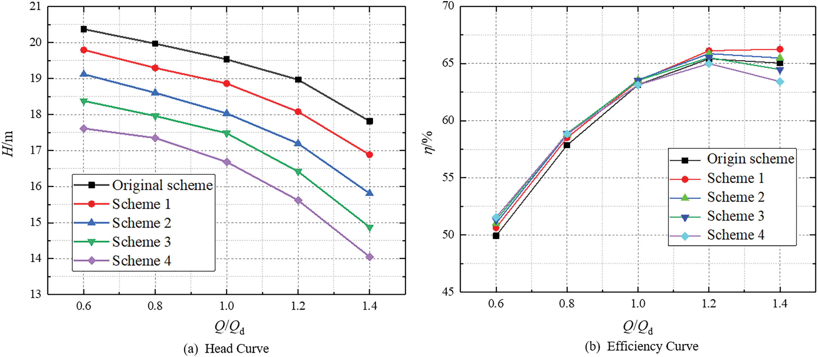
Figure 14: Performance curves of centrifugal pump
6.2 The Pressure Fluctuation in Volute of Centrifugal Pump
The frequency domain analysis of pressure pulsation data can determine the location and frequency domain characteristics of the main noise sources in the pump from the perspective of flow field, laying the foundation for acoustic analysis. So 12 monitoring points P0, P1 to P11 are selected in the middle section of volute to monitor the pressure of each monitoring point, as indicated in Fig. 15. For the convenience of analysis, the pressure pulsation coefficient Cp is defined as:
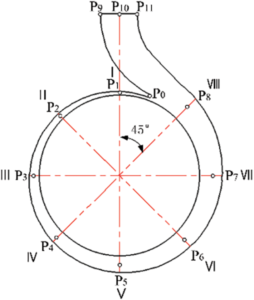
Figure 15: Distribution of monitoring points
In which, p refers the absolute pressure of a certain instantaneous monitoring point,
The pressure pulsation analysis results of monitoring points under various schemes are shown in Fig. 16. According to Fig. 16, the pressure pulsation peak value appears at the blade passing frequency, and the peak value is negatively related to the frequency. The pressure pulsation of monitoring point P0, P1, P2 inside the volute are larger, because when the fluid flows out of the flow passage of the high-speed rotating impeller, it constantly impacts the volute tongue and the I and II sections of the narrow flow passage. In addition, the larger pressure pulsation of P9, P10, P11 near the volute outlet is mainly resulting from the disturbance of the volute tongue. The smaller tongue clearance will block the flow of liquid, and the liquid accumulates continuously near the tongue area P0, merging with the mainstream liquid flowing from section VIII to form two streams of liquid, which impacts the volute outlet, thus forming a higher-pressure pulsation at the volute outlet. The pressure pulsation of all monitoring points decreases significantly when the cutting distance increases and the decrease of monitoring point P0 at the blade passing frequency are 6.45%, 8.14%, 14.96%, 11.65%, respectively. It shows that the cutting blade outlet can diminish the pressure pulsation effectively, and the greater the cutting distance is, the more the decrease of pressure pulsation is, but when the cutting distance exceeds 3 mm, the pressure fluctuation at the volute tongue P0 has a rising trend relative to cutting distance of 3 mm, if the fluid flows out of the impeller outlet, a large vortex will be generated, thus there is an obvious secondary flow at the impeller outlet, leading to a group of vortices in the opposite direction near the impeller outlet.
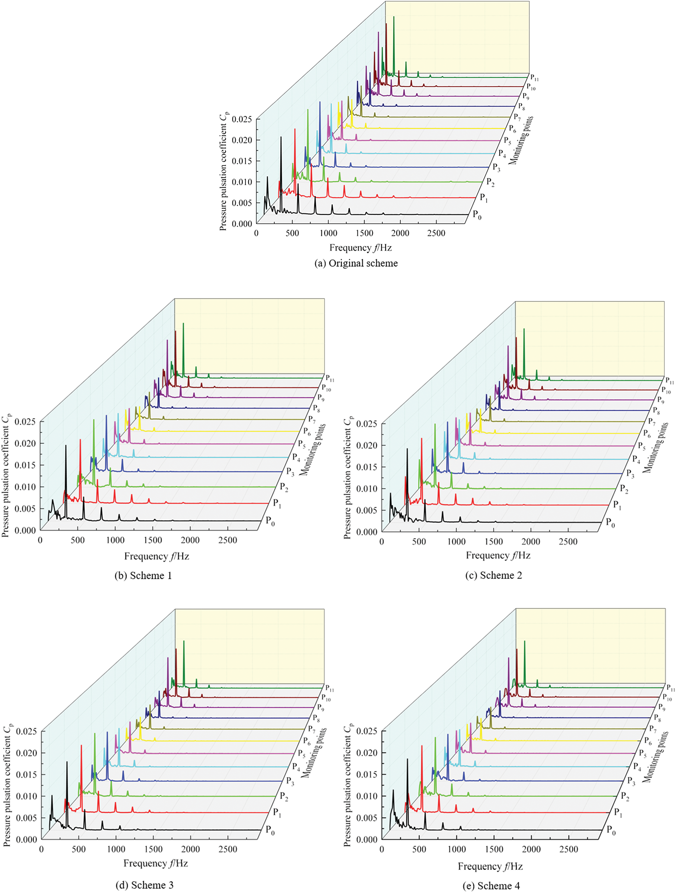
Figure 16: Pressure pulsation coefficient of monitoring points
For the purpose of further analyzing the influence of different schemes on the pressure pulsation distribution of its pump casing, the pressure of the pump casing at blade passing frequency for each scheme are shown in Fig. 17. When the cutting distance increases, the pressure of pump casing decreases gradually, and the maximum values of all schemes appear at the volute tongue and the outlet, which are consistent with the previous discussion. The pressure decreases rapidly when the cutting distance increases from 0 to 1 mm. Although the pressure reduces continuously when the cutting distance from 1 to 4 mm, compared with the cutting distance of 1 mm, the pressure decreases slightly, which shows that cutting blades can efficiently reduce the pressure pulsation. The tongue and outlet of the volute are the main parts that cause the noise of the centrifugal pump. When the cutting distance is 1 mm, the effect of pressure reduction is most obvious. With the continuous increase of cutting distance, the pressure at the blade passing frequency decreases continuously, but the pressure reduction is no longer obvious.
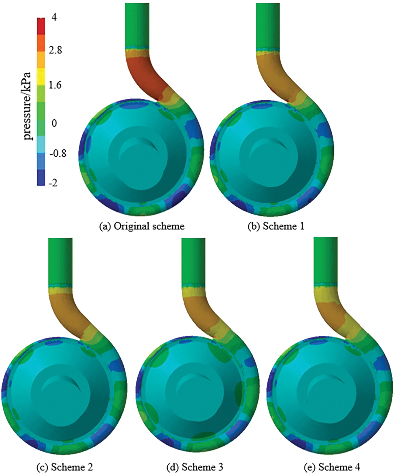
Figure 17: The distribution of pressure at blade passing frequency on pump casing
6.3 Noise Analysis of Centrifugal Pump
Fig. 18 shows the distribution of sound pressure level at blade passing frequency under different schemes, the noise source mainly occurs at the volute tongue and outlet, and the sound pressure is lower in other parts, which is similar to the results gained in Fig. 17. It indicates that the distribution of the pressure is closely related to the internal sound pressure level of centrifugal pump. In comparison to the original scheme, the sound pressure of each section in the volute passage changes significantly, and when the cutting distance increases, the internal sound pressure shows a downward trend obviously. The area of low sound pressure near the tongue has increased, and the decrease of sound pressure is the largest under scheme 4. Moreover, the area of low sound pressure under scheme 4 has gradually extended to the inlet section.
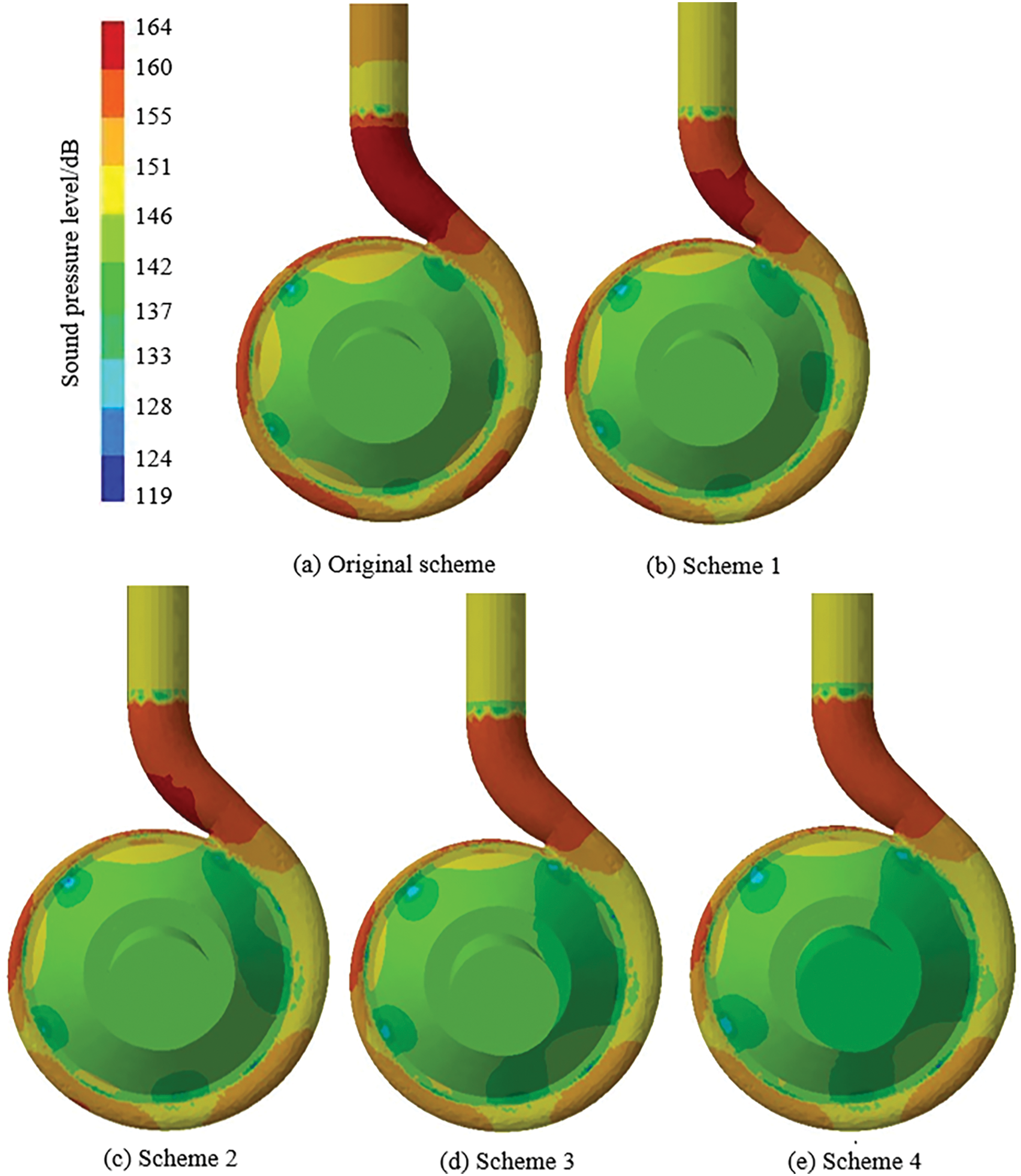
Figure 18: The sound pressure level at blade passing frequency
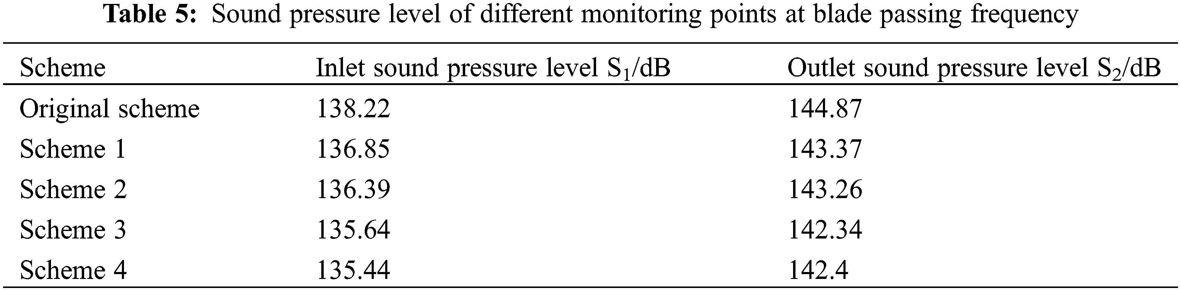
Table 5 shows the sound pressure level of the monitoring point S1 and S2 at blade passing frequency, the sound pressure of point S1 is slightly smaller than the point S2, which is mainly related to the higher pressure at the outlet. In comparison to the original scheme, the sound pressure at the inlet and outlet monitoring point have been reduced by 1%, 1.34%, 1.9%, 2.05% and 1.05%, 1.12%, 1.78%, 1.73%, respectively. It shows that cutting distance will directly affect noise of the centrifugal pump. Generally speaking, the greater the cutting distance is, the more pronounced the reduction range will be.
For the purpose of measuring the impact of the external sound pressure level of the centrifugal pump, it is important to monitor the area around the centrifugal pump, and the monitoring point is positioned at the central plane of the impeller 1000 mm, and 36 monitoring points are set up in the plane, which are uniformly arranged along the circumferential direction, as can be obtained from Fig. 19.
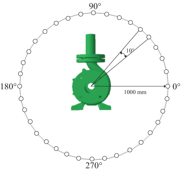
Figure 19: External directional field distribution of monitoring point
It is known from Fig. 20 that the change of the radiated noise distribution curve in the same plane is basically the same, the maximum sound pressure of all schemes are mainly concentrated in the direction of 150°. The maximum sound pressure under different schemes is 85.28, 82.95, 83.1, 82.12 and 82.88 dB, respectively, because the fluid near the volute tongue will have a strong impact when it flows, and the fluid near the tongue will radiate noise outward under the action of the impact force. At the same time, the directional sound pressure reduces with larger cutting distance, it shows that blade cutting can significantly reduce the sound pressure.
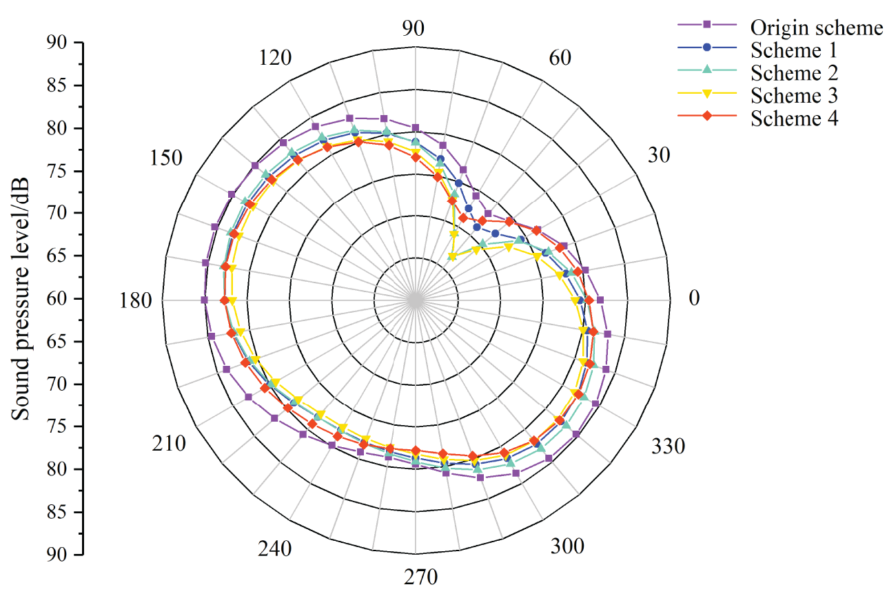
Figure 20: Directional distribution of radited noise at blade passing frequency
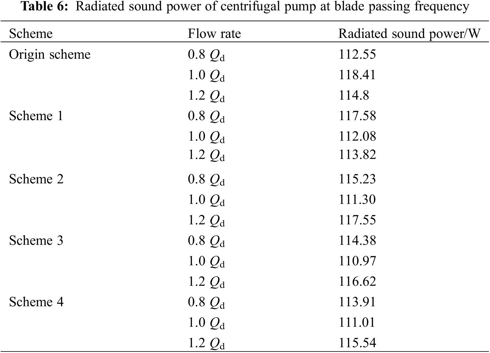
Table 6 shows the radiated sound power of centrifugal pump at blade passing frequency, under the flow rate 1.0 Qd, the decrease of the sound power is proportional to the cutting distance, that is, the greater the cutting distance, the greater the sound power reduction, and the change of sound power is more complex under non-design flow rates of 0.8 Qd and 1.2 Qd. When the cutting distance increases gradually, the sound power of the centrifugal pump increases first and subsequently decreases under non-design flow rates. However, the greater the cutting distance, the smaller the difference of radiated sound power under different flow rates, especially in scheme 4. The radiated sound power of the original scheme under 1.0 Qd is much larger than that of the non-design flow rates of 0.8 Qd and 1.2 Qd. The numerical comparison of sound power values under different schemes shows that the scheme 4 is the best.
In the present study, the flow field and sound field of the model pump are studied by cutting only the outlet edge of the blade. By analyzing the influence of blades under different schemes on the sound field of low specific speed centrifugal pump, combined with the dynamic-static interference in the flow field, the specific mechanism of noise reduction is explained, and the following conclusions are obtained:
(1) The size of the time step will affect the calculation result of the transient head. As the time step decreases, the change trend of the transient head becomes more stable. When the time step corresponds to impeller rotation angle of 3°, it is the critical value that can obviously enhance the accuracy of unsteady calculation. When the rotation angle of the impeller is less than 3°, the improvement of the unsteady calculation accuracy decreases.
(2) Cutting only the blades can ensure that the centrifugal pump has good hydraulic performance on the basis of effectively reducing the pressure pulsation and volute noise level.
(3) Cutting only the blades reduces the sound field inside and outside the centrifugal pump significantly, and the directivity of the sound pressure level all appears at the volute tongue. Considering that the performance of the centrifugal pump will be significantly affected when the cutting distance is larger, the centrifugal pump has the best overall performance when the optimal cutting percentage is 1.21% (the clearance ratio between the impeller blade and tongue is 8.57%).
Acknowledgement: None.
Funding Statement: The authors received no specific funding for this study.
Author Contributions: Conceptualization, Methodology, Investigation, Writing—Original Draft, Writing—Review and Editing, Tianpeng Li; Formal Analysis, Supervision, Conceptualization, Methodology, Formal Analysis, Yujun Duan; Formal Analysis, Validation, Qianghu Ji. All authors reviewed the results and approved the final version of the manuscript.
Availability of Data and Materials: The datasets generated and/or analyzed during the current study are available from the corresponding author on reasonable request.
Ethics Approval: Not applicable.
Conflicts of Interest: The authors declare no conflicts of interest to report regarding the present study.
References
1. Namazizadeh M, Gevari MT, Mojaddam M, Vajdi M. Optimization of the splitter blade configuration and geometry of a centrifugal pump impeller using design of experiment. J Appl Fluid Mech. 2020;13(1):89–101. [Google Scholar]
2. Birajdar R, Patil R, Khanzode K. Vibration and noise in centrifugal pumps-sources and diagnosis methods. In: 3rd International Conference on Integrity, Reliability and Failure, 2009; Porto, Portugal; p. 20–4. [Google Scholar]
3. Gangipamula R, Ranjan P, Patil RS. Flow-induced noise sources and reduction methods in centrifugal pumps: a literature review. Phys Fluids. 2022;34(8):081302. [Google Scholar]
4. Daryan H, Hussian F, Hickey JP. Sound generation mechanism of compressible vortex reconnection. J Fluid Mech. 2020;933:A34. [Google Scholar]
5. Dreyer M, Decaix J, Münch-Alligné C, Farhat M. Mind the gap: a new insight into the tip leakage vortex using stereo-PIV. Exp Fluids. 2014;55:1–13. [Google Scholar]
6. Hu FF, Chen T, Wu DZ, Wang LQ. Experimental study on flow-induced vibration and noise of the mixed flow pump with guide vane. J Eng Thermophys-Rus. 2013;34(5):874–7. [Google Scholar]
7. Langthjem MA, Olhoff N. A numerical study of flow-induced noise in a two-dimensional centrifugal pump. Part II. Hydroacoustics J Fluid Struct. 2004;19(3):369–86. doi:10.1016/j.jfluidstructs.2004.01.002. [Google Scholar] [CrossRef]
8. Guo C, Gao M, He S. A review of the flow-induced noise study for centrifugal pumps. Appl Sci. 2020;10(3):1022. doi:10.3390/app10031022. [Google Scholar] [CrossRef]
9. Wu CS, Yang J, Yang S, Wu P, Huang B, Wu DZ. A review of fluid-induced excitations in centrifugal pumps. Mathematics. 2023;11(4):1026. doi:10.3390/math11041026. [Google Scholar] [CrossRef]
10. Jiang AH, Zhang ZY, Zhang Y, Hua HX. Summary and prospect of research on centrifugal pump noise. Vibration Shock. 2011;30(2):77–84. [Google Scholar]
11. Arbey H, Bataille J. Noise generated by airfoil profiles placed in a uniform laminar flow. J Fluid Mech. 1983;134:33–47. doi:10.1017/S0022112083003201. [Google Scholar] [CrossRef]
12. Desquesnes G, Terracol M, Sagaut P. Numerical investigation of the tone noise mechanism over laminar airfoils. J Fluid Mech. 2007;591:155–82. doi:10.1017/S0022112007007896. [Google Scholar] [CrossRef]
13. Howe MS. Noise produced by a saw-tooth trailing edge. J Acoust Soc Am. 1991;90(1):482–7. doi:10.1121/1.401273. [Google Scholar] [CrossRef]
14. Gangipamula R, Ranjan P, Patil RS. Comparative studies on air borne noise and flow induced noise of a double suction centrifugal pump. Appl Acoust. 2023;202:109148. doi:10.1016/j.apacoust.2022.109148. [Google Scholar] [CrossRef]
15. Li GP, Sun LH, Wang ZY, An CG, Guo C, Cheng S, et al. Investigation on the changing characteristics of flow-induced noise in a centrifugal pump. Fluid Dyn Mater Proc. 2021;17:989–1001. doi:10.32604/fdmp.2021.016507. [Google Scholar] [CrossRef]
16. Cheng XR, Wang P, Zhang SY. Correlation research between turbulent pressure pulsation and internal sound field characteristics of centrifugal pump. J Therm Sci. 2021;30:100–10. doi:10.1007/s11630-020-1253-y. [Google Scholar] [CrossRef]
17. Dong R, Chu S, Katz J. Effect of modification to tongue and impeller geometry on unsteady flow, pressure fluctuations, and noise in a centrifugal pump. J Fluid Eng-T ASME. 1997;119(3):506–15. doi:10.1115/1.2841152. [Google Scholar] [CrossRef]
18. Shim HS, Kim KY. Relationship between flow instability and performance of a centrifugal pump with a volute. J Fluid Eng. 2020;142(11):111208. doi:10.1115/1.4047805. [Google Scholar] [CrossRef]
19. Cheng XR, Li TP, Wang P. Study on the influence of blade outlet cutting on hydraulic noise of centrifugal pump with low specific speed. Adv Mech Eng. 2020;12(9):1–12. doi:10.1177/1687814020960630. [Google Scholar] [CrossRef]
20. Guo C, Lv F, Gao M, Wei W, Cheng S. Investigation on the influence of number of blades on flow-induced noise optimization design of a centrifugal pump. J Mech Sci Technol. 2022;36(10):5107–16. doi:10.1007/s12206-022-0923-y. [Google Scholar] [CrossRef]
21. Wei ZC, Li N, Xiao RF, Tao R, Yang W, Hu HL. Reduction of flow-induce noise of a high-speed centrifugal pump by applying blade leaning on guide van. J Phys: Conf Series. 2022;2217(1):012035. [Google Scholar]
22. Jia XQ, Li YP, Zhang J, Yan CS, Lin Z, Zhu ZC. Research on the effects of volute area ratios on centrifugal pump internal flow and noise. Phys Fluids. 2024;36(7). doi:10.1063/5.0212150. [Google Scholar] [CrossRef]
23. Ohashi H. Vibration and oscillation of hydraulic machiner (monograph). Aldershot: Cambridge University Press; 1991. [Google Scholar]
24. Yakhot V, Thangam S, Gatski TB, Orszag SA, Speziale CG. Development of turbulence models for shear flows by a double expansion technique. Phys Fluids A: Fluid Dyn. 1992;4(7):1510–20. doi:10.1063/1.858424. [Google Scholar] [CrossRef]
25. Ffowcs Williams JE, Hawkings DL. Sound generation by turbulence and surfaces in arbitrary motion. Philoso Trans Royal Society London. Series A, Math Phys Sci. 1969;264(1151):321–42. doi:10.1098/rsta.1969.0031. [Google Scholar] [CrossRef]
26. Si QR. Investigation on hydraulic design of centrifugal pumps with low noise and mechanism of rotor-stator interaction (Ph.D. Thesis). Jiangsu University: China; 2014. [Google Scholar]
27. Fan CP, Yan XL, Ma HZ. Effect of impeller turning method on pump performance. General Mach. 2009;7:78–80. [Google Scholar]
28. Zhao CS, Chai K. Simulation study on the flow-induced vibration and noise in marine centrifugal pumps. J Vib Control. 2024;30(11–12):2549–67. doi:10.1177/10775463231180017. [Google Scholar] [CrossRef]
29. Wang YQ, Ding ZW. Influence of blade number on flow-induced noise of centrifugal pump based on CFD/CA. Vacuum. 2020;172:109058. doi:10.1016/j.vacuum.2019.109058. [Google Scholar] [CrossRef]
30. Dai C, Dong L, Xia B, Kong FY. Noise reduction in centrifugal pump as turbine: influence of leaning blade or tongue. J Vibroeng. 2016;18(4):2667–82. doi:10.21595/jve. [Google Scholar] [CrossRef]
31. Ferna’ndez J, Barrio RL, Blanco E, Parrondo J, Marcos A. Experimental and numerical investigation of a centrifugal pump working as a turbine. In: ASME 2009 Fluids Engineering Division Summer Meeting, 2009; p. 471–9. doi:10.1115/FEDSM2009-78524. [Google Scholar] [CrossRef]
32. Wang WB, Xiang Y, Li ZX. Analysis of flow noise characteristics of marine vertical centrifugal pump. Ship Eng. 2024;46(3):22–30. [Google Scholar]
Cite This Article
 Copyright © 2025 The Author(s). Published by Tech Science Press.
This work is licensed under a Creative Commons Attribution 4.0 International License , which permits unrestricted use, distribution, and reproduction in any medium, provided the original work is properly cited.
 Downloads
 Citation Tools