 Open Access
ARTICLE
A Study on the Performances and Parameter-Dependence of Water-Alternating-Gas Flooding for Conglomerate Reservoirs
1 CNPC Advisory Center, CNPC, Beijing, 100724, China
2 Fengcheng Oilfield Operation Area of PetroChina, Xinjiang Oilfield Company, PetroChina, Karamay, 834000, China
3 State Key Laboratory of Enhanced Oil Recovery, PetroChina, Beijing, 100083, China
4 Research Institute of Petroleum Exploration and Development, PetroChina, Beijing, 100083, China
5 Polytechnic Institute, Hebei Normal University, Shijiazhuang, 050000, China
6 Hebei Provincial Key Laboratory of Information Fusion and Intelligent Control, Shijiazhuang, 050000, China
* Corresponding Author: Hao Kang. Email:
(This article belongs to the Special Issue: Fluid and Thermal Dynamics in the Development of Unconventional Resources II)
Fluid Dynamics & Materials Processing 2025, 21(2), 293-308. https://doi.org/10.32604/fdmp.2025.058989
Received 25 September 2024; Accepted 16 December 2024; Issue published 06 March 2025
Abstract
To address the water sensitivity of conglomerate reservoirs, a series of core sensitivity tests were conducted to evaluate the effects of varying ionic content. These findings serve as a foundation for improving reservoir fluid dynamics and optimizing the concentration of anti-swelling agents in water flooding operations. The experiments revealed a marked disparity in response between cores with differing permeabilities. In Core No. 5, characterized by low permeability, a 0.5% anti-swelling agent achieved only a modest 7.47% reduction in water sensitivity. Conversely, in the higher-permeability Core No. 8, a 5% anti-swelling agent significantly reduced the water sensitivity index by 44.84% while enhancing permeability. Further, two displacement strategies—gas flooding following water flooding and water flooding after gas injection—were tested to assess the potential of CO2 water-alternating-gas (WAG) displacement. CO2 injection after water flooding in Core No. 5 increased oil recovery by 9.24%, though gas channeling, evidenced by a sharp rise in the gas-liquid ratio, emerged as a critical concern. In Core No. 8, water flooding following gas injection failed to improve recovery, likely due to pronounced water sensitivity, reduced permeability, and the formation of dominant flow channels under high displacement pressure, which limited sweep efficiency.Keywords
Oil and gas form the bedrock of economic growth and human sustenance, intricately linked to the pillars of energy security and the welfare of populations [1,2]. In today’s rapidly evolving landscape, the metamorphosis of energy sources is gaining momentum, characterized by heightened efficiency, environmental purity, and a broad spectrum of diversified options [3,4]. Concurrently, a complex interplay unfolds: the indispensable nature of conventional fossil fuels clashes with the unstoppable tide of energy transition; international collaborations in energy deepen alongside the intensifying rivalry of global energy politics. Within this intricate web of advancements and tensions, safeguarding oil and gas security has ascended to a paramount position, embodying a comprehensive, foundational, and strategic cornerstone for both economic vitality and societal progress. It stands as a linchpin issue, intricately entwined with the overarching narrative of development and survival on a global scale [5–7].
In order to ensure a stable supply of oil and gas resources, oil and gas field development workers have carried out a lot of exploration around new methods and technologies to enhance oil recovery. Based on the research of scholars and the successful application of Toe to Heel Air Injection (THAI) technology, Li et al. [8] analyzed the principle of THAI technology and pointed out its advantages. The effects of technological parameters such as ignition temperature, gas injection intensity, injection pressure and well pattern are discussed, which lays a foundation for the parameter optimization design of THAI technology in heavy oil recovery. Liu et al. [9] discussed eight effective oil displacement methods, such as the physicochemical method, microbial technology, gas flooding and thermal oil recovery, and systematically described the principles and requirements of key technologies for reservoir exploitation. The field application in Bashkortostan Oilfield has been analyzed accordingly in detail to prove the effectiveness of the tertiary oil recovery technology. Akhlaghi et al. [10] used a 2-D Hele-Shaw physical model packed sands to conduct visual experiments of CO2 injection; the influence of CO2 injection rate and absolute permeability are studied in detail. Chen et al. [11] developed a pragmatic method for optimizing the production-injection parameters in a field-scale project using water-alternating-gas (WAG). Sensitivity analysis of WAG parameters, including injection rates, WAG ratios, cycle times for injectors, and bottomhole pressures (BHPs) for producers on oil recovery, is conducted, and a field case demonstrates the successful application of this technique. Mahdavi et al. [12] experimentally studied the effect of water flooding and Carbonated Water Injection (CWI) on oil recovery in the vertically oriented pore and core scales. Water flooding, secondary and tertiary CWI, and CO2 water alternating gas (CO2-WAG) processes were simulated by CMG compositional software. Results show that CWI proved to be effective under Newfoundland’s typical reservoir conditions, especially when replacing water flooding. To solve the problem of bottom water coning in the production of sandstone reservoirs with bottom water, Zhu et al. [13] designed a new method to enhance oil recovery, that is, the method of water extraction to eliminate coning. Then, the application scope, application time and economic risk are studied deeply by using reservoir numerical simulation technology, and through the analysis of examples, it is proved that this method has better economic benefits in improving oil recovery in the middle and late stages of sandstone bottom water reservoir development. With the expansion and gradual deepening of the application scale of enhanced oil recovery (EOR) technology, the traditional enhanced oil recovery technology is facing more and more challenges. Wang et al. [14] systematically summarized the research progress of new EOR technologies from three aspects of new materials, new fields and new methods. On this basis, three core directions for exploring a new generation of EOR technologies in the future are proposed: “low cost, green and low carbon, and revolutionary breakthrough”. Based on the thermochemical reaction between a gas-producing aqueous solution and a low concentration of active acid, Huang et al. [15] proposed the in-situ generation of CO2 for oil displacement. The main advantage of this technology is to overcome the negative impact and constraints of CO2 flooding on the environment. Li et al. [16] illustrated the principle of a new technology to improve the fluidity of oil near the wellbore by introducing alternating current and using a downhole oscillator to generate oscillation and evaluated the application of this technology in heavy oil fields in Brazil, Texas and Venezuela. Wang et al. [17] conducted an experimental study on the Daqing Xingshugang Oilfield to evaluate the effectiveness of enhanced oil recovery (EOR) methods following strong ASP (Alkali-Surfactant-Polymer) flooding. Their findings indicate that high-concentration polymer flooding post-ASP flooding significantly improves oil production. Taking into account the reservoir characteristics, equipment pressure resistance, and a comprehensive assessment of economic and technical viability, they concluded that the alkali-free binary compound system holds greater potential for application.
As a special type of oil and gas reservoir, conglomerate reservoir is facing many challenges in exploration, development and engineering. Firstly, there are great differences in the depositional models of different conglomerate depositional bodies, such as alluvial fan and fluvial facies, as well as the hydrocarbon accumulation models of oil and gas reservoirs, so it is necessary to carry out in-depth research on the hydrocarbon generation mechanism of source rocks, the characterization of conglomerate depositional system and the prediction of dominant reservoirs [18–20]. Secondly, as water injection technology advances, its efficacy diminishes year by year, highlighting the urgent need to address challenges in developing efficient production techniques for conglomerate reservoirs. This urgency is amplified by the necessity to meticulously characterize the intricate pore structures of reservoirs with varying physical properties and at different stages of development. Furthermore, devising precise analyses of seepage patterns and implementing high-efficiency extraction methods tailored to the pronounced heterogeneity of these reservoirs are imperative tasks that demand immediate attention [21–23]. Thirdly, conglomerate reservoirs are highly heterogeneous, with low drilling rates, long drilling cycles and large differences in reservoir stimulation effect in the later stage. Future studies should, therefore focus on the evaluation of mechanical properties of mid-deep conglomerates and the research on efficient and low-cost hydraulic fracturing technology in conglomerate reservoir [24–26].
Based on the historical field production data and related experimental tests of the reservoir, the target conglomerate formation is of obvious water sensitivity, velocity sensitivity and salt sensitivity [27]. The inherent characteristics of reservoirs contribute to a decline in permeability during water flooding, which directly hampers the injection efficiency of wells and severely impacts oil production negatively. To address these challenges, initial steps involve conducting water sensitivity tests on conglomerate cores to assess their responsiveness under varying ionic concentrations. Following this, two distinct core displacement experiments are executed: gas flooding subsequent to water flooding and vice versa, utilizing CO2 as the gas medium for Water-Alternating-Gas (WAG) displacement studies. The overarching goal of this research is to furnish the oilfield with insights that facilitate more precise adjustments to production strategies, thereby ensuring sustained and stable output.
The cores taken from the field are labeled, the original fluid in the core is washed out, porosity and permeability are tested, and drying is carried out.
The parameters of cores used in these tests are as shown in Table 1 below.

2.2 Water Sensitivity Analysis Experiment of Conglomerate Cores
According to China’s petroleum and natural gas industry standard “SYT 5358-2010 Reservoir sensitivity flow experimental evaluation method”, No. 5 and No. 8 cores are selected for the water sensitivity test, and the experimental device is shown in Fig. 1.
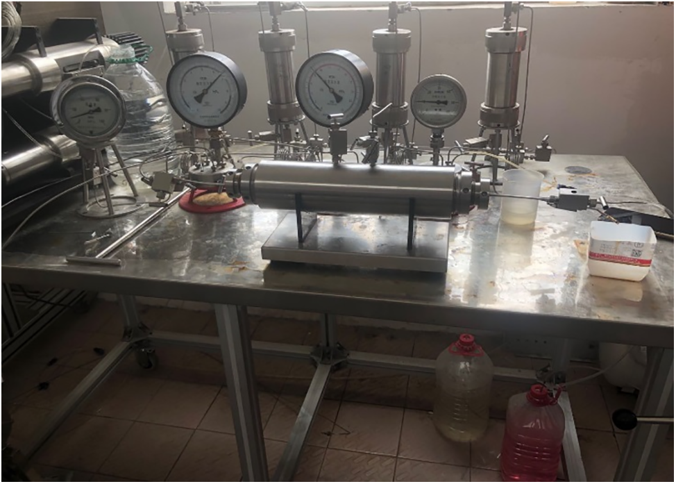
Figure 1: Water sensitivity test device of conglomerate cores
The water sensitivity of the rock sample is evaluated by the water sensitivity index, and the calculation method of the water sensitivity index is as follows:
The water sensitivity experiment was conducted on No. 8 and No. 5 cores treated with epoxy resin glue. The experimental setup involves maintaining a confining pressure that is consistently 2 MPa higher than the displacement pressure. Formation water, an anti-swelling agent solution, 50% concentration formation water, and deionized water are injected in sequence. Core permeability changes are then measured. By comparing these results under different water qualities, the core’s response to varying water conditions can be better understood.
Formation water, formation water of 50% salinity, 0.5% solution of anti-swelling agent and deionized water were injected into core No. 5 successively, and the test results are shown in Table 2 and Fig. 2, respectively. It can be seen from the results that formation water is injected when the injection pore volume is less than 1 PV. When the injection volume is 1 to 1.5 PV, formation water with salinity of 50% is injected. When the injection volume is 1.5 to 2.5 PV, 0.5% anti-swelling agent solution is injected. Then, the deionized water is injected until the cumulative injection pore volume was approximately 5.5 PV. In the formation water injection stage, with the increase of the cumulative injection pore volume, the water sensitivity index shows a gradually increasing trend. Specifically, when the cumulative injection pore volume is 0.5 and 1 PV, the corresponding water sensitivity index is 21.45% and 23.44%, respectively. This means that the water sensitivity of the core is enhanced with the increase of the cumulative water injection. At the injection stage of 50% concentration formation water, the water sensitivity index also shows a trend of continuous increase with the increase of cumulative injection. Specifically, when the cumulative injection pore volume is 1.5 PV, the corresponding water sensitivity index increases by 52.11%. This means that the injection of 50% concentration of formation water further enhances the water sensitivity of the core. When 0.5% anti-swelling agent solution was injected, the water sensitivity index showed a certain downward trend with the increase of the cumulative water injection. The corresponding water sensitivity indexes are 47.32% and 44.64% when the cumulative injection volume are 2 and 2.5 PV, respectively. During the subsequent stage of injecting deionized water, the water sensitivity index progressively increases as the cumulative injection volume rises. Specifically, the water sensitivity indices are 67.88%, 79.77%, 84.14%, 86.32%, and 86.46% corresponding to cumulative injection pore volumes of 3, 3.5, 4, 4.5, and 5.5 PV, respectively. Overall, after an intermediate injection of a 0.5% anti-swelling agent solution, there is a slight recovery in permeability, but it significantly decreases again following the continued injection of deionized water.

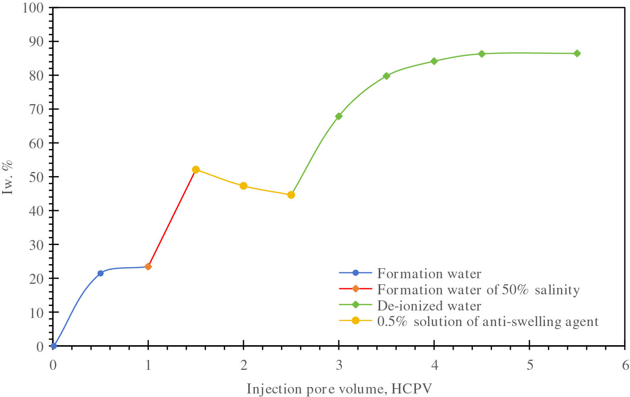
Figure 2: Water sensitivity test results of core No. 5
Formation water, formation water of 50% salinity, deionized water and 5% anti-swelling agent solution were successively injected into No. 8 core, and the test results are shown in Table 3 and Fig. 3, respectively. It can be seen from the test results that formation water is injected when the injection pore volume is within 19.43 PV. When the injection pore volume increases from 19.43 to 41.16 PV, the formation water of 50% salinity is injected. Deionized water is injected at pore volumes between 41.16 to 57.15 PV. Then 5% anti-swelling agent solution was injected until the cumulative injection pore volume was nearly 92 PV. In the formation water injection stage, with the increase of the injection, the water sensitivity index shows a generally increasing trend. Specifically, the corresponding water sensitivity indices are 9.51% and 14.69% when the cumulative injection pore volume are 4.59 and 19.43 PV, respectively. This means that the sensitivity of the core to water is enhanced with the increase of the cumulative injection. During the injection phase involving formation water with 50% salinity, the water sensitivity index exhibits a consistent upward trend as the cumulative injection volume escalates. Specifically, for cumulative injection pore volumes ranging from 20.05 to 41.16 PV, the water sensitivity index rises by 14.82% and 35.56%, respectively. This indicates that injecting formation water with a 50% salinity level exacerbates the core’s water sensitivity. In the subsequent stage of deionized water injection, the water sensitivity index demonstrates a rapid increase. For cumulative injection pore volumes of 42.28, 43.08, 44.4, 56.69, and 57.15 PV, the corresponding water sensitivity indices are 77.33%, 83.6%, 84.87%, 90.55%, and 91.43%, respectively. When 5% anti-swelling agent solution is gradually injected, the water sensitivity index shows a gradually decreasing trend, and when the cumulative injection pore volumes are 57.86, 81.36 and 91.63 PV, the corresponding water sensitivity indexes are 65.35%, 53.76% and 44.84%, respectively. From the view of overall trend, after the injection of deionized water, the core permeability is greatly reduced, the displacement rate is slowed down, and the water sensitivity index reaches more than 90%. After the injection of anti-swelling agent solution, the displacement rate is significantly improved, and the permeability is restored.

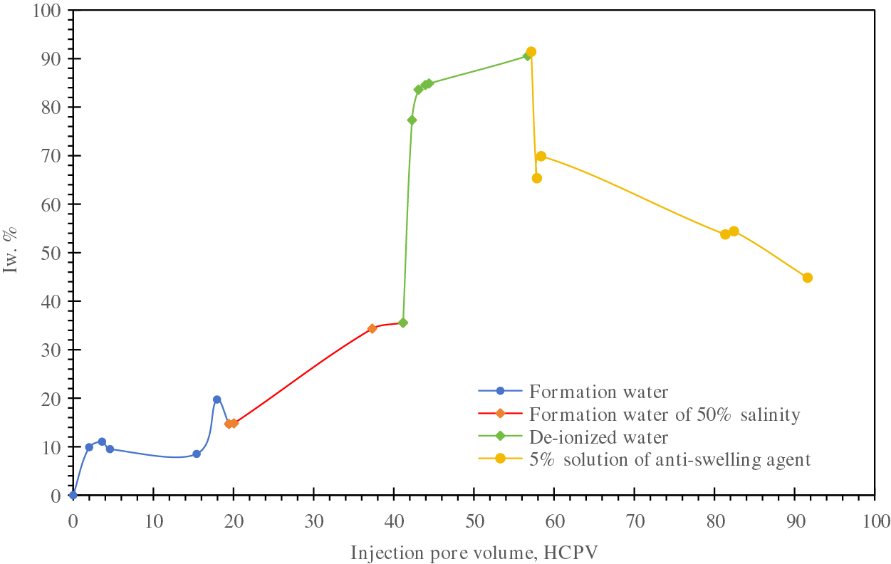
Figure 3: Water sensitivity test results of core No. 8
By comparing the experimental results of No. 5 core and No. 8 core, it can be seen that the water-sensitive expansion of No. 5 core has begun to occur after the injection of formation water, although the water-sensitive index has been alleviated after the injection of 0.5% anti-swelling agent solution, the effect is not obvious, and the water-sensitive degree is close to 90% after injection of deionized water, so it can be judged that the water sensitivity of the core is very strong, and 0.5% anti-swelling agent has almost no effect. The permeability of core No. 8 is relatively high, but after injecting deionized water, the water sensitivity index also rises to nearly 90%, indicating an extremely strong water sensitivity in this reservoir formation. Following the addition of a 5% anti-swelling agent solution, permeability begins to increase, eventually reducing the water sensitivity index to below 50% and demonstrating excellent anti-swelling effectiveness.
2.3 Evaluation Experiment of Core Displacement Effect
The experimental process is designed according to the Technical Specification for Screening of Enhanced Oil Recovery Methods (Petroleum and Natural Gas Industry Standard of the People’s Republic of China SYT 6575-2003), which are necessary to analyze the flow mechanism and dynamics of reservoir fluids and thus affect the development effect of reservoirs, as shown in Fig. 4. The specific experimental scheme is shown in Table 4.
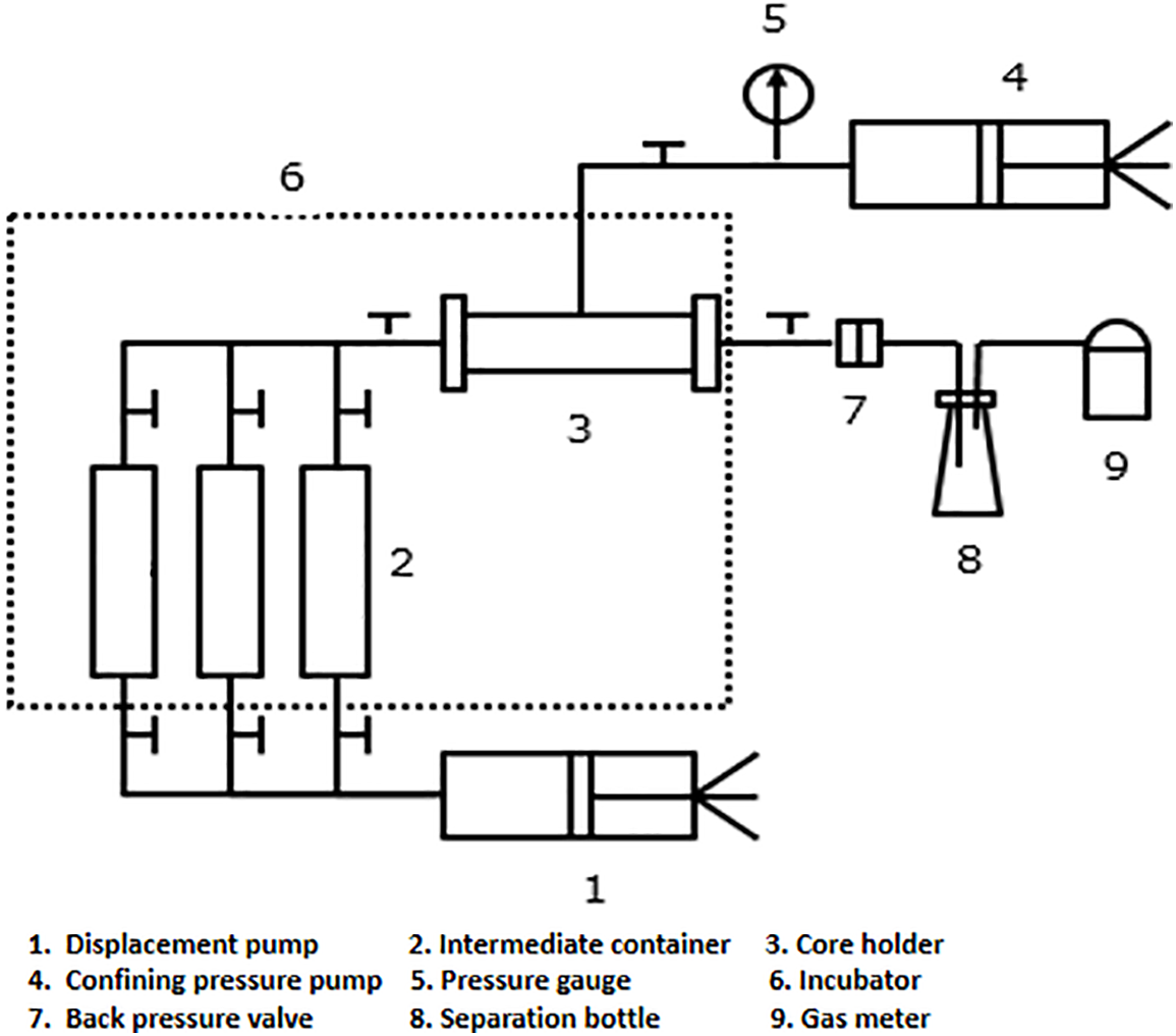
Figure 4: Flow chart of core displacement experiment

In order to evaluate the water sensitivity of the core and the effect of depressurization and augmented injection of the injected solution, the change of displacement resistance during the displacement process is calculated according to Formula (2) below:
In the formula above:
2.3.1 Effect Evaluation of Water Flooding Followed by CO2 Flooding
After drying, vacuuming and aging treatment, the displacement experiment was carried out on the No. 5 core. Firstly, a water flooding experiment was carried out on core No. 5, which was saturated with oil at a pressure of 8 MPa. Then, the core was taken out to measure the wet weight, calculate the saturated oil volume, adjust the confining pressure and injection pressure, and keep the confining pressure higher than the injection pressure by 2 MPa. Finally, the injection water containing 2% anti-swelling agent was injected until the water cut at the outlet was 98% or no fluid flowed out at the outlet end, and the final recovery was calculated. After that, the CO2 displacement experiment is carried out by adjusting the back pressure to 25 MPa.
The experimental results of No. 5 core in the water flooding stage are shown in Table 5 and Fig. 5. The results show that the oil recovery increases from 0.0% to 44.79% with the increase of injection pore volume from 0.0 to 0.88 PV. This indicates that the injected water containing 2% anti-swelling agent can effectively drive the oil and gas in the core to move to the outlet, thus significantly improving the oil recovery. When the initial injection volume is small (about 0.00–0.25 PV), the oil recovery increases rapidly, which may be related to the fact that the oil that is easy to flow in the core is first exploited. With the further increase of the injection volume, the increasing rate of the oil recovery gradually slows down because the remaining oil may be more in the tiny pores of the reservoir, which is difficult to be displaced. At the same time, with reference to the water cut of produced liquid, the stage of significant increase in oil recovery mainly happened before the water breakthrough, and after the water breakthrough, the growth rate of oil recovery slows down. In general, the increase in injection volume plays a positive role in improving the oil recovery; the final recovery reaches to about 45%, and the final water cut reaches more than 90%.

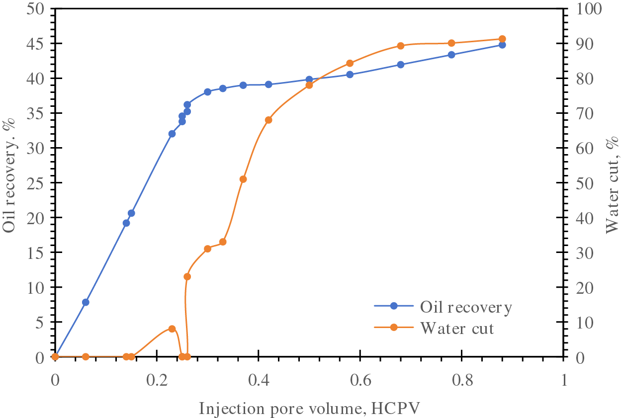
Figure 5: Change of recovery and water cut of No. 5 core in water flooding stage
The displacement resistance of the experimental core during water flooding is calculated, as shown in Fig. 6. The points on the line represent the logarithmic values of the displacement resistance. As illustrated, when the injection volume reaches 0.14 to 0.37 PV, the displacement resistance exhibits a sharp increasing trend. This increase is attributed to the water sensitivity effect caused by the injection of formation water, which leads to a decrease in core percolation capacity and a gradual rise in displacement pressure difference.
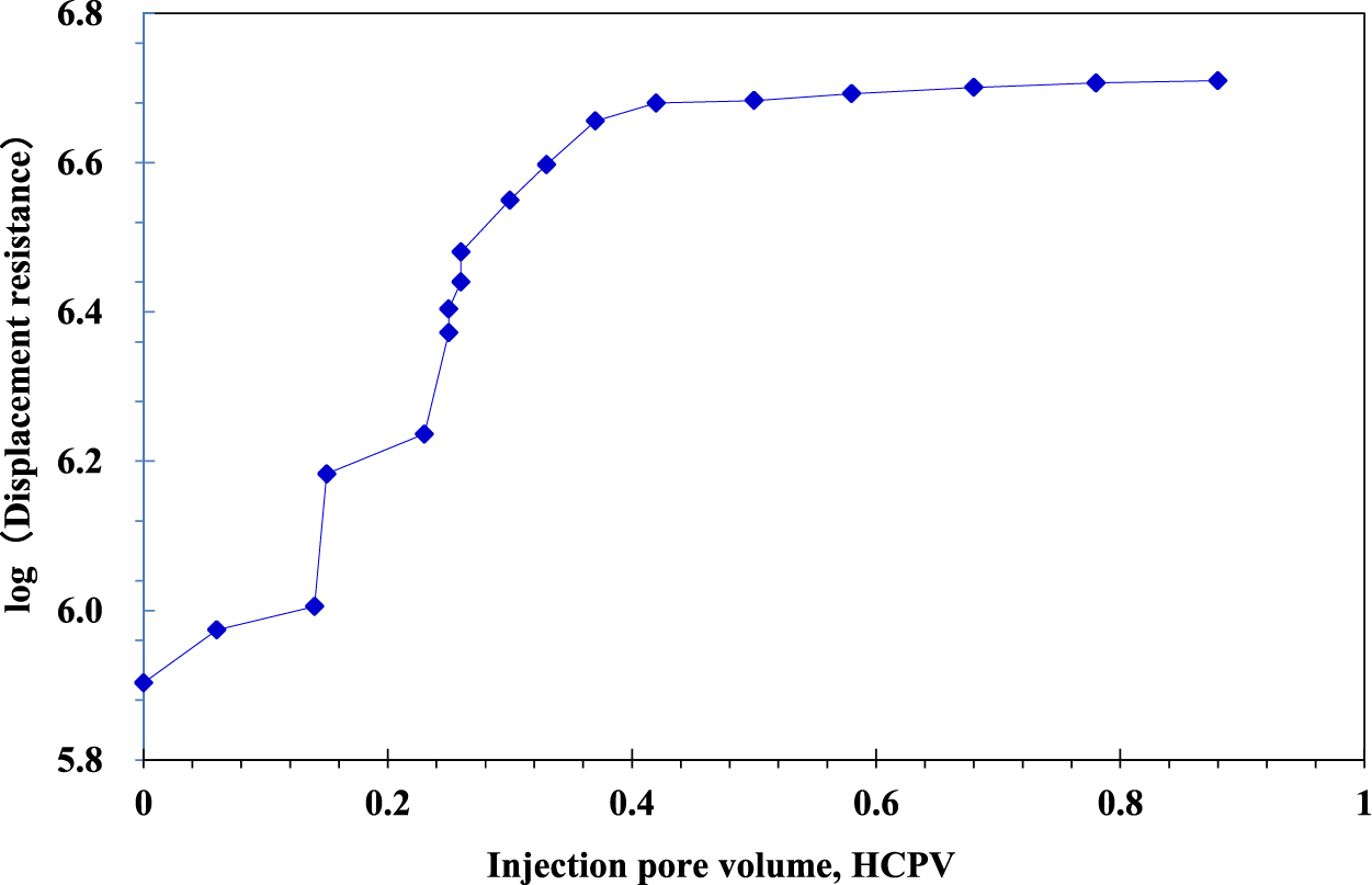
Figure 6: Displacement resistance change of No. 5 core in water flooding stage
The No. 5 core is converted to CO2 flooding after water flooding, and oil continues to be produced. The experimental results are shown in Table 6 and Fig. 7. Specifically, the stage recovery increases rapidly to 4.69% as the gas injection pore volume increases to about 4.16 PV. At this stage, with the increase of gas injection volume, the recovery is significantly improved, indicating that the injected fluid can efficiently push the oil in the core to the core outlet. However, from the aspect of the gas-liquid ratio, when the injection pore volume is 0.13 PV, the gas-liquid ratio has reached to 20.83, indicating that the gas has reached the outlet through the core, and the gas-liquid ratio continues to rise rapidly with the continuous injection of gas. This also suggests that enough attention should be paid to the prevention of gas channeling when gas flooding development is conducted to further enhance oil recovery. However, with the increase of the injection gas volume, there is still oil flowing out from the outlet. When the injection pore volume reaches 93.20 PV, the recovery factor is increased by about 10% compared with that in the water flooding stage. This also shows that gas flooding after water flooding can further improve the recovery of the reservoir, and CO2 flooding can be carried out after water flooding to enhance oil recovery.

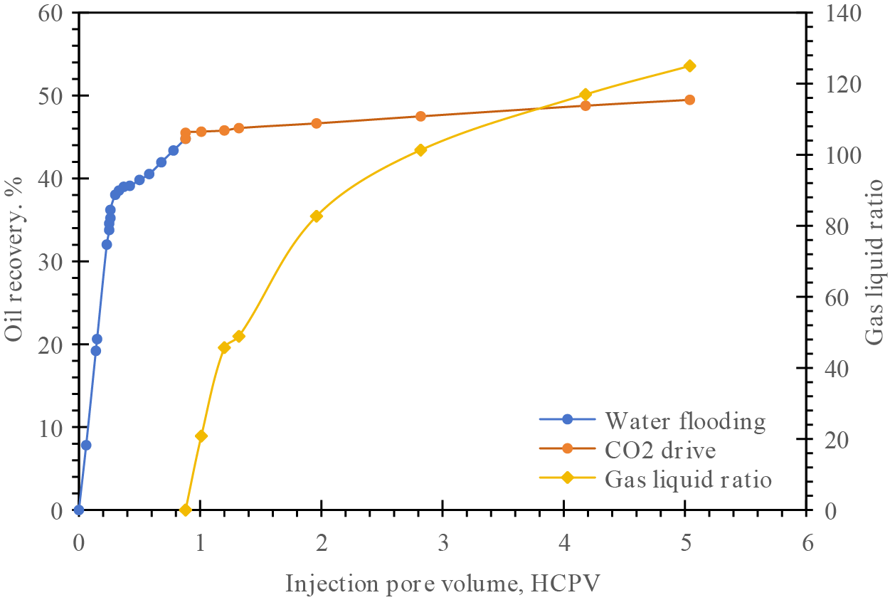
Figure 7: Gas flooding recovery and gas-liquid ratio of gas flooding stage in core No. 5
2.3.2 Effect Evaluation of CO2 Flooding Followed by Water Flooding
After drying, vacuuming, and aging treatments, a displacement experiment was conducted on core No. 8. The back pressure at the outlet end was set to 25 MPa. The displacement pressure was gradually increased until continuous gas outflow was observed. Subsequently, changes in oil production, gas output, outlet pressure, and inlet pressure were recorded over time. The relationship between cumulative oil production and cumulative injection volume, along with changes in the gas-oil ratio, were calculated. Following the gas injection, a water injection displacement experiment was performed. The back pressure valve was connected, the back pressure was adjusted to 25 MPa, and the system was switched to water injection to measure the final oil recovery.
As that can be seen from Table 7 and Fig. 8, during the gas flooding stage, the cumulative recovery and the gas-liquid ratio show a certain growth trend with the increase of the injection pore volume. Specifically, in the initial stage, that is, when the injection pore volume is 5.77 PV, the recovery percent is 10%. With the increase of injection pore volume, the recovery increases gradually. When the injection pore volume is 29.3 PV, the recovery reaches 19%. When the injection pore volume is more than 105.98 PV, the recovery is basically stable between 33% and 38%, and then the injection pore volume continues to increase, but the increasing rate of the recovery slows down until the injection pore volume reaches about 1388 PV, the cumulative recovery is basically close to and maintained at about 60%. In the aspect of produced gas-liquid ratio, at the beginning, when the injection pore volume is 5.77 PV, the gas-liquid ratio is 34; with the increase of the injection pore volume, the gas-liquid ratio gradually increases, when the injection pore volume is 29.3 PV, the gas-liquid ratio is 221. The injection pore volume continues to increase, and the gas-liquid ratio continues to increase, reaching 450 at the injection pore volume of 105.98 PV; the subsequent results show that the growth rate of the gas-liquid ratio seems to slow down and finally stabilizes at the level of about 9000. To sum up, with the increase of gas injection pore volume, the oil recovery increases gradually at the beginning and tends to be stable after a certain range, while the gas-liquid ratio continues to rise, but the growth rate gradually slows down in the later period.

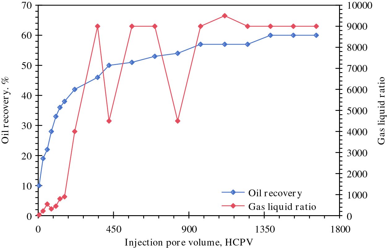
Figure 8: Change of recovery and gas-liquid ratio in gas flooding stage of No. 8 core
The displacement resistance of the core during gas flooding is calculated, as shown in Fig. 9. The results demonstrate that the gas flooding resistance decreases as the injection volume increases. This reduction occurs because water sensitivity is not a concern during gas injection, allowing the gas flow channels to become smoother with the outflow of oil.
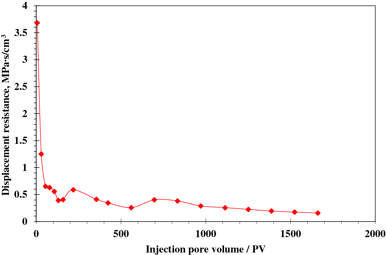
Figure 9: Variation of gas displacement resistance in No. 8 core
After water flooding is switched to gas flooding in No. 8 core, only water and gas are produced, even though there is a pressure difference of 25 MPa between the inlet and outlet, and the recovery is not further improved. On the one hand, it is considered that the recovery of the gas flooding stage has been very high, on the other hand, it shows that the mainstream channel has been formed in the core, and the water injected subsequently flows out directly from the channel, which can not improve oil production. After taking out the core from the holder, it is found that the core has obvious cracks, which indicates that obvious fluid channeling has formed during the experiment (Fig. 10).

Figure 10: Physical image of No. 8 core after water flooding
Generally speaking, the effectiveness of water flooding following gas flooding is poor. Analysis indicates that, on the one hand, the residual oil remaining after gas flooding is minimal within the core. On the other hand, due to strong water sensitivity, the permeability of the core significantly decreases as water enters. This results in ineffective water flooding and may even cause core rupture due to substantial pressure differences.
To address the significant water sensitivity issue in a conglomerate reservoir located in Northwest China and enhance the performance of injection wells, a core water sensitivity test was conducted. This experiment aimed to assess the water-induced reactions at varying ion concentrations, thereby informing the selection of an appropriate anti-swelling agent and determining its optimal concentration. Subsequently, a core displacement experiment employing CO2 and water as the displacing fluids was performed to investigate the effectiveness of WAG (water-alternating-gas) displacement techniques. The results show that the No. 5 core swells after injection of formation water, and the effect is not obvious after injection of 0.5% anti-swelling agent. After the injection of deionized water, the water sensitivity index of No. 5 core reaches nearly 90%, showing a very strong water sensitivity. The permeability of No. 8 core is relatively high, and the water sensitivity index increases to nearly 90% after injecting deionized water and decreases to less than 50% after adding 5% anti-swelling agent; the effect is remarkable. In the follow-up experiments, CO2 flooding is performed after water flooding in the No. 5 core, and when the gas injection pore volume reaches 93.20 PV, the oil recovery is increased by about 10% compared with that in the water flooding stage. This also shows that gas flooding after water flooding can further improve the recovery of the reservoir, and CO2 flooding can be conducted after water flooding to enhance oil recovery. Water flooding did not further improve the recovery after gas flooding in No. 8 core, which is most likely due to the permeability decrease caused by the strong water sensitivity of formation, and the core fracture appeared due to the large displacement pressure difference in the experiment, forming a fluid channeling channel. It is proposed that CO2 flooding could be a viable option to boost oil recovery during the present development phase. However, if WAG (water-alternating-gas) injection is considered, a comprehensive assessment of the risks associated with gas channeling and reservoir water sensitivity damage is imperative. Additionally, meticulous optimization of the timing for water and gas injections, as well as the determination of appropriate slug sizes, is crucial.
Acknowledgement: The authors acknowledge the contributions of CNPC Advisory Center, State Key Laboratory of Enhanced Oil Recovery and Research Institute of Petroleum Exploration and Development, PetroChina, Hebei Normal University, and Xinjiang Oilfield Company that aided the efforts of the authors.
Funding Statement: The authors received no specific funding for this study.
Author Contributions: Study conception and design: Haishui Han, Jian Tan, Hao Kang; data collection: Junshi Li, Hao Kang; analysis and interpretation of results: Changhong Zhao, Ruoyu Liu, Qun Zhang; draft manuscript preparation: Zemin Ji, Hao Kang. All authors reviewed the results and approved the final version of the manuscript.
Availability of Data and Materials: The data that support the findings of this study are available from the corresponding author upon reasonable request.
Ethics Approval: Not applicable.
Conflicts of Interest: The authors declare no conflicts of interest to report regarding the present study.
References
1. Szymczak P. CNPC, Sinopec drill ultra deep in search of energy security. J Pet Technol. 2023;75(7):20–5. doi:10.2118/0723-0020-JPT. [Google Scholar] [CrossRef]
2. Mukherjee S. Technology focus: EOR operations (June 2023). J Pet Technol. 2023;75(6):77–8. doi:10.2118/0623-0077-JPT. [Google Scholar] [CrossRef]
3. Alnuaim S. Energy, environment, and social development: the technology arm of sustainability. J Pet Technol. 2019;71(3):10–1. doi:10.2118/0319-0010-JPT. [Google Scholar] [CrossRef]
4. Feder J. Transforming natural resource management for a sustainable planet. J Pet Technol. 2019;71(8):76–8. doi:10.2118/0819-0076-JPT. [Google Scholar] [CrossRef]
5. Ferrari A. Guest Editorial: the unavoidable truth: the world’s growing need for oil. J Pet Technol. 2024;76(6):10–1. doi:10.2118/0624-0010-JPT. [Google Scholar] [CrossRef]
6. Gillick S, Babaei M. In-situ hydrogen production from natural gas wells with subsurface carbon retention. SPE J. 2024;29(4):2119–29. doi:10.2118/219449-PA. [Google Scholar] [CrossRef]
7. Adebayo A, Rezk M, AlYousef Z, Badmus S, Babu R. A study of CO2 storage in bimodal carbonate aquifer rocks: challenges and enhancement through foaming. SPE J. 2024;29(11):6312–31. doi:10.2118/223103-PA. [Google Scholar] [CrossRef]
8. Li W, Wu X, Liu P. Toe to heel air injection new method of EOR. J Southwest Pet Univ (Sci Technol Ed). 2008;30(1):78–80. [Google Scholar]
9. Liu Y, Chen S. Application of new techniques for increasing oil recovery in oilfields in Bashkortostan. Energy Conserv Pet Petrochem Ind. 2003;19(5):8–10. [Google Scholar]
10. Akhlaghi N, Kharrat R, Mahdavi S. Gas assisted gravity drainage by CO2 injection. Energ Source Part A. 2012;34(17):1619–27. doi:10.1080/15567036.2011.598906. [Google Scholar] [CrossRef]
11. Chen S, Li H, Yang D, Tontiwachwuthikul P. Optimal parametric design for water-alternating-gas (WAG) process in a CO2-miscible flooding reservoir. J Can Pet Technol. 2010;49(10):75–82. doi:10.2118/141650-PA. [Google Scholar] [CrossRef]
12. Mahdavi S, James L. High pressure and high-temperature study of CO2 saturated-water injection for improving oil displacement; mechanistic and application study. Fuel. 2020;262:116442. doi:10.1016/j.fuel.2019.116442. [Google Scholar] [CrossRef]
13. Zhu Z, Song W. A new improved recovery method for complicated sandstone reservoir with bottom water. Xinjiang Pet Geol. 2001;22(2):144–6. [Google Scholar]
14. Wang R, Lun Z, Lv C, Wang Y, Tang Y, Wang X. Research status and development trends of worldwide new technologies for enhanced oil recovery. Pet Geol Recov Effic. 2021;28(5):81–6. [Google Scholar]
15. Huang A, Tian F, Jin X, Feng S, Zhou R. In-situ generation of carbon dioxide: new way to increase oil recovery. Energy Conserv Pet Petrochem Ind. 2002;18(7):5–7. [Google Scholar]
16. Li C, Ji P. EOR by electro-acoustic reservoir stimulation: a new approach. Energy Conserv Pet Petrochem Ind. 2003;19(4):1–3. [Google Scholar]
17. Wang Z, Lu X, Jiang X, Zhang Y, Song R. Experimental method about enhancing oil recovery after alkaline/surfactant/polymer flooding: take Xingshugang oilfield in Daqing as research object. J Petrochem Univ. 2016;29(2):65–70. [Google Scholar]
18. Gao W, Li Y, Kong D, Luan H, Chen X, Qi H, et al. Effect of grain size distribution on pore size distribution characteristics in a conglomerate reservoir from an alluvial fan via artificial rock approach. SPE J. 2023;28(6):3063–78. doi:10.2118/217426-PA. [Google Scholar] [CrossRef]
19. Olszowska D, Gallardo-Giozza G, Domenico C, Torres-Verdín C. Angle-Dependent ultrasonic wave reflection for estimating high-resolution elastic properties of complex rock samples. Petrophysics. 2023;64(3):402–19. doi:10.30632/PJV64N3-2023a6. [Google Scholar] [CrossRef]
20. Craddock P, Srivastava P, Datir H, Rose D, Zhou T, Mosse L, et al. Enhanced mineral quantification and uncertainty analysis from downhole spectroscopy logs using variational autoencoders. Petrophysics. 2021;62(6):614–29. [Google Scholar]
21. Wang Y, Qu Z, Zhang J, Qian C, Ding M, Kang Y, et al. Influence of distribution patterns of high-permeability zones on polymer crossflow in conglomerate oil reservoirs. Pet Geol Recov Eff. 2019;26(6):92–9. doi:10.13673/j.cnki.cn37-1359/te.2019.06.012. [Google Scholar] [CrossRef]
22. Carrizo N, Santiago E, Saldungaray P. An integrated petrophysical characterization of a siliciclastic tight gas reservoir in Neuquén Basin, Western Argentina. Petrophysics. 2021;62(6):711–36. doi:10.30632/SPWLA-2021-0044. [Google Scholar] [CrossRef]
23. Gao F, Xiao L. A method to identify pore fluids in heterogeneous conglomerate reservoirs using a nuclear magnetic resonance log with oil-based mud invasion. SPE J. 2024;29(8):4043–53. doi:10.2118/219764-PA. [Google Scholar] [CrossRef]
24. Wei Y, Lu X, Xu J. A systematical review of the largest alkali-surfactant-polymer flood project in the world: from laboratory to pilots and field application. SPE J. 2024;29(8):4147–65. doi:10.2118/215058-PA. [Google Scholar] [CrossRef]
25. Hong Y, Wu T. Fracturing improvement technology of Triassic low permeability conglomerate reservoir in Mabei oilfield. Pet Geol Eng. 2022;36(3):104–8. [Google Scholar]
26. Emami-Meybodi H, Ma M, Zhang F, Rui Z, Rezaeyan A, Ghanizadeh A, et al. Cyclic gas injection in low-permeability oil reservoirs: progress in modeling and experiments. SPE J. 2024;29(11):6217–50. doi:10.2118/223116-PA. [Google Scholar] [CrossRef]
27. Xu H, Ma H, Yin X, Zhao X, Liu X, Lai N. Study on formation damage with water flooding for ultra-low permeability reservoir in Xinjiang Oilfield. Lithol Reserv. 2013;25(2):100–6. [Google Scholar]
Cite This Article
 Copyright © 2025 The Author(s). Published by Tech Science Press.
This work is licensed under a Creative Commons Attribution 4.0 International License , which permits unrestricted use, distribution, and reproduction in any medium, provided the original work is properly cited.


 Submit a Paper
 Propose a Special lssue
 View Full Text
 Download PDF
 Downloads
 Citation Tools