
 Submit a Paper
 Propose a Special lssue
 Open Access
ARTICLE

Effects of Fuel Injection and Ignition on the Direct-Start Process of a Gasoline Direct Injection (GDI) Engine
1 Department of Mechanical and Electrical Engineering, Yantai Institute of Technology, Yantai, 264000, China
2 Key Laboratory for Power Machinery and Engineering of Ministry of Education, Shanghai Jiao Tong University, Shanghai, 200240, China
3 Aviation Piston Engine Team, Beijing Power Machinery Institute, Beijing, 100074, China
* Corresponding Author: Lei Shi. Email:
Fluid Dynamics & Materials Processing 2025, 21(2), 405-426. https://doi.org/10.32604/fdmp.2024.056396
Received 22 July 2024; Accepted 11 October 2024; Issue published 06 March 2025
 View Full Text
 Download PDF
Abstract
During the highly transient process of the direct-start in a four-cylinder GDI engine, each cylinder exhibits specific characteristics in terms of in-cylinder conditions and energy demands, necessitating different control for each cylinder. However, recent studies have paid insufficient attention to cylinders other than the first starting cylinder. This paper proposes a comprehensive control strategy based on experimental data from the direct-start process of the second, third, and fourth cylinders, aiming to enhance the characteristics of combustion and emission performance through the optimization of injection timing, equivalence ratio, and ignition timing. The research findings indicate that the second cylinder should inject fuel approximately 10 ms after the first cylinder ignites to mix thoroughly the fuel with air. The ignition timing of the second cylinder should be close to the highest point of the piston movement to minimize hindrance to the piston compression process. The third and fourth cylinders should adopt a delayed injection timing strategy to prevent the escape of injected fuel caused by low engine speed. The optimal ignition timing for the third cylinder is 20°CA BTDC, while the fourth cylinder should be ignited earlier due to its stronger airflow and faster formation of a mixture that can be ignited. As the fuel injection quantity increases, the power output of the three cylinders enhances, but at the same time, emissions also increase. Therefore, their optimal equivalence ratios are determined as 1.2, 1.4, and 1.2, respectively, striking a balance between combustion and emission performances.Keywords
In cities with insufficient transportation infrastructure, vehicle idling is very common due to traffic congestion [1]. During idling, the engine suffers from insufficient intake, increased throttle power loss, and incomplete fuel combustion, leading to negative impacts on engine efficiency and emissions [2–8]. Research has shown that compared to continuous idling, restarting the engine after shutting off for more than 7 s can reduce fuel consumption and avoid the generation of a significant amount of pollutants during idle conditions [9]. Therefore, start-stop technology has gained popularity in recent years. By implementing stop-start technology, the vehicles can shut down the engine when the engine is idle and subsequently reactivate it according to the driver’s request. Tests conducted on vehicles equipped with start-stop systems have demonstrated fuel economy improvements of 5.3% in the city cycle and approximately 4.0% in the highway drive cycle [10]. Moreover, start-stop technology also contributes to emission reduction such as NOx [11,12]. The existing stop-start systems typically employ motor-driven starting methods, using an auxiliary motor as the power output source for starting the engine after shutdown [13,14].
Direct-start is another strategy for achieving start-stop technology. Typically applied in GDI engines, the start-up methods can be categorized into forward direct start and reverse direct start. In the forward direct start process, the expansion cylinder is ignited first, compressing the mixture in the compression cylinder, followed by the ignition of the compression cylinder, which pushes the crankshaft to continue rotating forward, thus completing the start process. The reverse direct start process usually selects the cylinder that is on the compression stroke when the engine is stopped as the starting cylinder (also known as the first cylinder), injecting fuel into the starting cylinder, igniting the mixture, and pushing the crankshaft to rotate in reverse to start the engine [15–20]. Current research on forward direct start is limited. Compared to reverse direct start, it requires overcoming additional mechanical resistance from engine accessories like water pumps and oil pumps. Sun et al. [21] studied the compression cylinder in forward direct start and found that when the ignition timing of the compression cylinder remains close to the top dead center (TDC) of compression, the engine can achieve improved dynamic performance. This paper focuses on the reverse direct start process and will hereafter simply refer to it as a direct start. Relevant research mainly focuses on the control strategy of the first cylinder in the four-cylinder GDI engine. Kramer et al. [22] measured the oxygen content in the first cylinder during the direct-start process using a gas sampling valve (GSV) and improved the oxygen concentration in the cylinder by controlling the throttle valve, idle speed, and valve timing. Kulzer et al. [23] conducted research on the success rate of the direct-start process under different engine initial temperature conditions. Zhong et al. [24] studied the effects of the initial piston position, coolant temperature, and fuel injection pressure on the combustion and power performance of the first cylinder. Xie et al. [25] studied the start performance of the first and second cylinders of a four-cylinder engine and found that the best time to ignite the mixture in the second cylinder is close to the moment when the crankshaft changes the direction of rotation.
The working conditions of each cylinder in the direct-start process exhibit significant differences, necessitating separate adjustment and control of fuel injection and ignition parameters for each cylinder; and develop an overall control strategy ultimately. However, there are currently few research reports on the overall control of this process, so there is not enough data and complete research results to provide to engine manufacturers, which will directly lead to an increase in the uncontrollability of the direct-start process, i.e., leading to possible insufficient and unstable in-cylinder combustion. When the direct start is employed, the combustion in the first cylinder is imperative since it generates the vast majority of the energy for the engine [23,26]. However, the lack of fuel-air movement leads to poor mixture preparation, thus hampers the combustion. The fluid-dynamic aspects, such as inadequate airflow patterns and insufficient mixing of fuel during the direct-start process, must be considered. In particular, the incomplete development of swirl and tumble motions at low engine speeds complicates mixture formation, necessitating the use of high-pressure injections to promote atomization and ensure a homogeneous air-fuel mixture. Additionally, low in-cylinder temperatures can hinder fuel evaporation, leading to stratified mixtures that challenge stable ignition and combustion. It has been demonstrated that the enrichment of fuel and multiple injection strategies can effectively solve this issue [27–29]. Thereafter, the initiated combustion in the first cylinder rotates the crankshaft reversely while compressing the mixture in the second cylinder, which helps to obtain the forward rotation ability through the combustion. The power generated by combustion requires to be able to push the piston to the TDC. As the third cylinder enters the expansion stroke, due to the complete compression process and sufficient air volume in the cylinder, the third cylinder can output more power, driving the engine to run smoothly. The fourth cylinder undergoes a complete air change process, with a high engine speed during the intake process, resulting in stronger airflow movement in the cylinder. The starting process of the third and fourth cylinders approaches the normal working process of the engine compared with the second cylinder. Because part of the gas from the first cylinder is discharged into the intake port and the throttle opening is small, the pressure in the intake pipe is very high; thus the air volume in the cylinder prior to the ignition of the third and fourth cylinders is greater than the air intake volume of the single cylinder at idle speed.
It should be noted that the low speed and the lack of ventilation of the second cylinder can also result in poor mixing. In the second cylinder, inadequate fuel atomization and poor mixing are compounded by insufficient air movement, particularly during low-speed direct starts. This can lead to incomplete combustion and increased hydrocarbons (HC) emissions. Addressing these challenges requires an optimized injection strategy that enhances mixture formation and compensates for the limited air movement within the cylinder. Therefore, the crucial factor ensuring a successful direct start lies in not only the combustion improvement of the first cylinder but also the second cylinder to generate the required energy to propel the piston through TDC [25]. Additionally, precise control of fuel injection and ignition parameters is required for the third and fourth cylinders due to their unique operating conditions in order to achieve optimal performance. This paper aims to develop an overall fuel injection strategy for the direct-start process by analyzing the combustion, motion, and HC emissions characteristics of the second, third, and fourth cylinders. The research findings will contribute to the optimization of control parameters for all four cylinders in the direct start process.
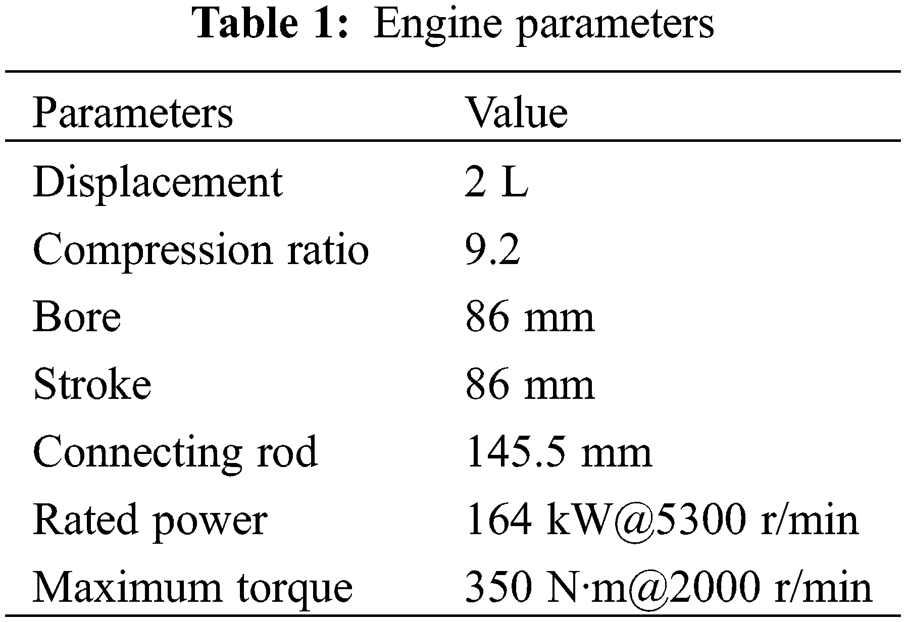
Fig. 1 illustrates the schematic diagram of the engine test bed. The engine utilized in this experiment is a four-cylinder, inline, direct-injection gasoline engine. Table 1 displays the parameters of the engine.
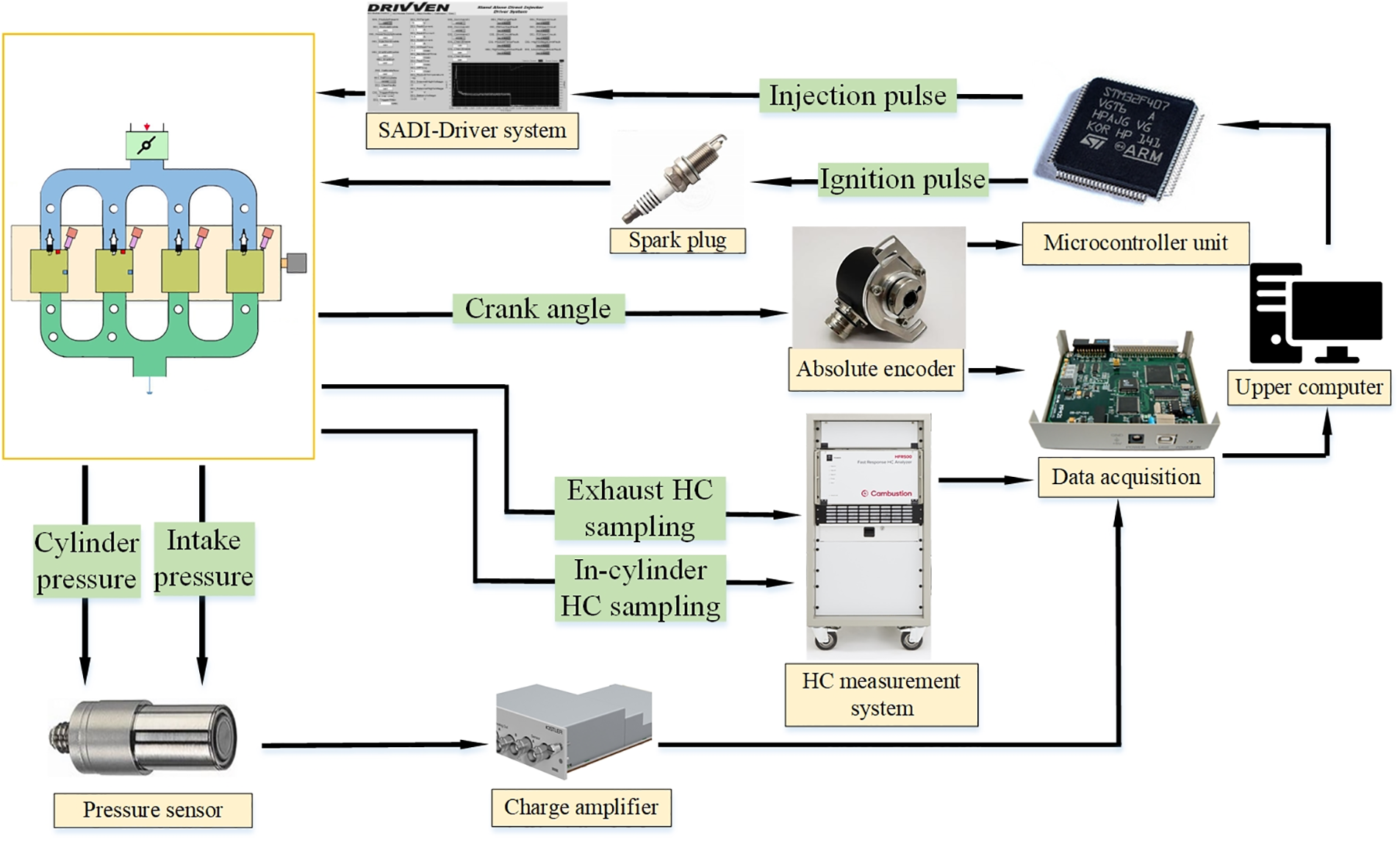
Figure 1: The schematic diagram of the engine test bench
Pressure sensors are installed in the cylinders and intake manifold to measure pressure variations. The crankshaft angle is detected by a single-turn absolute encoder. Considering that the crankshaft requires two complete rotations per cycle, the encoder is connected to a transmission mechanism with a gear ratio of 1:2 to ensure that the encoder signal corresponds to the 720-degree crankshaft angle signal. The HFR500 flame ionization detector has two sampling channels, which are used for in-cylinder sampling and exhaust sampling of hydrocarbons (HC) separately. Since the HFR500 uses propane as the reference for calibration, the measured value is the concentration value of C3. Since HFR500 uses propane as a calibration reference, for all hydrocarbons measured, the measured value is represented in terms of C3 concentration. For in-cylinder sampling, a numeric conversion is required to analyze the fuel concentration in the mixture. The air-fuel ratio of the in-cylinder mixture can be calculated using the following formula:
The PPM denotes the concentration of the C3 detected by the HFR500 detector. Mair and MC3H8 correspond to the molecular mass of the air and propane. The stoichiometric concentration of propane in the air is approximately 42,000 ppm, which can be further calculated to obtain the equivalence ratio of the mixture.
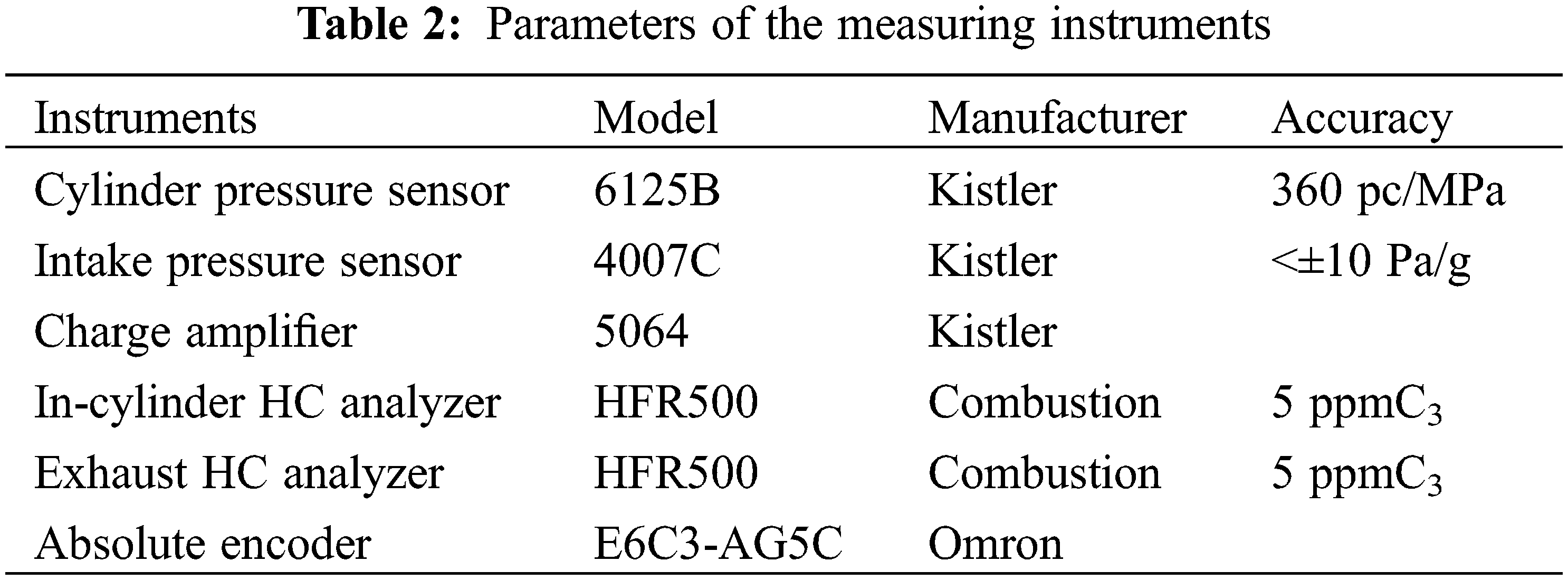
The electronic control system has been designed as follows. The traditional engine control unit (ECU) controls engine starting based on parameters such as engine speed during reverse drag starting [30]. However, in the case of direct starting, fuel injection; and ignition control need to be based on the crankshaft angle position and other engine states before starting. Furthermore, precise control within each engine cycle is required. Therefore, a microcontroller unit (MCU) is utilized for controlling the direct starting process instead of direct control by the ECU. The MCU adopts the STM32 core and the control program is written in the C language. The SADI driver system is employed to boost the coil current of the fuel injectors. The MP421 acquisition module is used for data acquisition from the measuring instruments. Table 2 lists the parameters of the measuring instruments.
The firing sequence in the direct-start process differs slightly from the conventional engine firing sequence, as it undergoes a reverse rotation process. Table 3 presents the working process of each cylinder in the direct-start process. In a typical four-stroke engine, the firing sequence is 1-3-4-2. However, in the case of the direct-start process, the earliest ignited cylinder is the one in the compression stroke at the time of engine shutdown. Therefore, the actual firing sequence for the direct-start process is 1-2-3-4 when the starting cylinder is the first cylinder. To achieve optimal combustion and emission performance in the first cylinder, the starting position for the first cylinder is set at 80°CA before the top dead center (BTDC), and the ignition timing is set at 70 ms after fuel injection, according to the recommendation of Reference [31]. Other experimental conditions include pressurizing the fuel in the high-pressure oil circuit using 99.9% high-purity nitrogen to achieve an injection pressure of 3–4 MPa, maintaining the fuel temperature inside the injectors at approximately 30–40 degrees Celsius, and keeping the coolant temperature between 60–90 degrees Celsius.
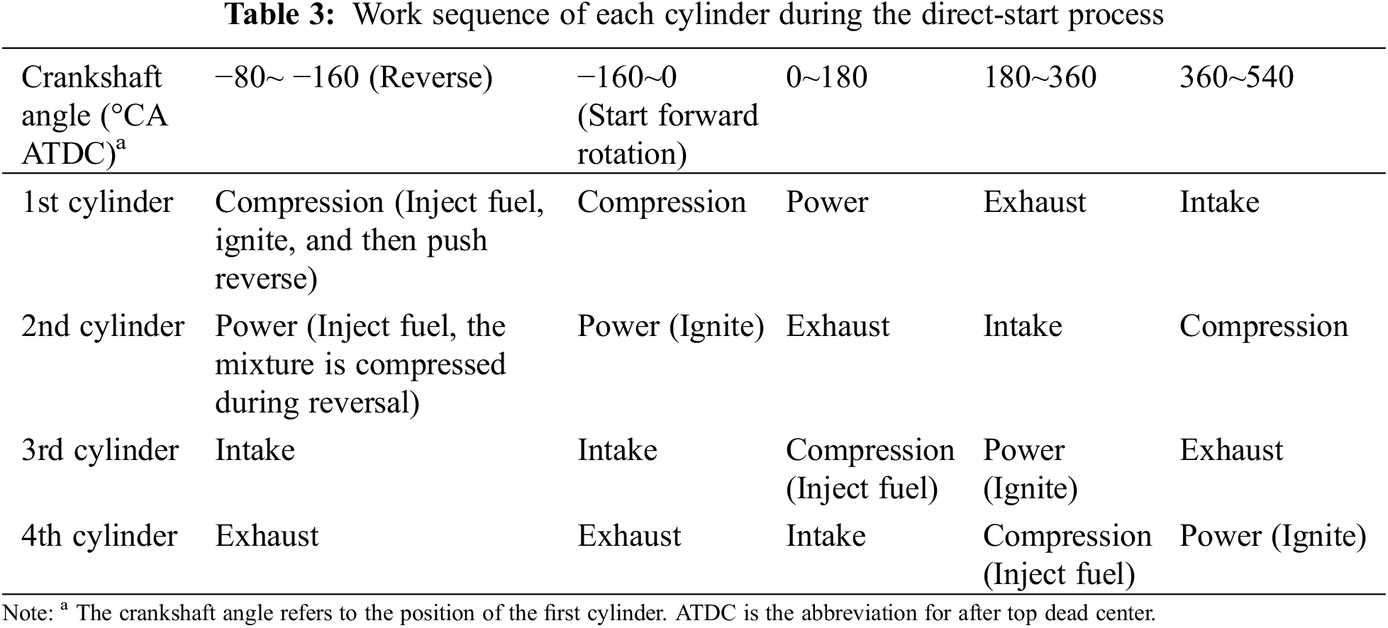
Table 4 presents the experimental cases. In Cases 1 to 3, the Fuel Equivalence Ratio and Ignition Timing are kept constant while varying the Injection Timing. Case 1 investigates the Injection Timing of the second cylinder, with an experimental range of 10–60 ms after the start of ignition of the first cylinder (ASOIG) and a step size of 10 ms. Case 2 focuses on the Injection Timing of the third cylinder, with a range of 100–250°CA BTDC and a step size of 50°. Case 3 examines the Injection Timing of the fourth cylinder, ranging from 100–300°CA BTDC with a 50° step size.
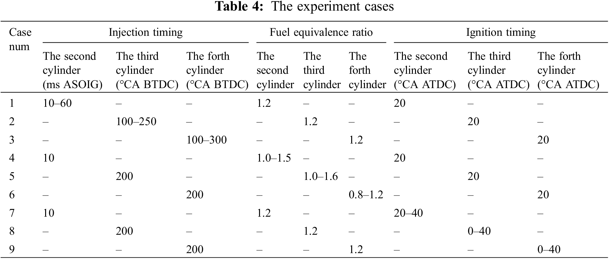
In Cases 4 to 6, the Injection Timing and Ignition Timing remain constant while the Fuel Equivalence Ratio is varied. Case 4 explores the Fuel Equivalence Ratio for the second cylinder, with experimental points at 1.0, 1.2, and 1.5. Case 5 investigates the third cylinder’s Fuel Equivalence Ratio, with a range of 1.0–1.6 and a step size of 0.2. Case 6 studies the Fuel Equivalence Ratio of the fourth cylinder, with a range of 0.8–1.2 and a step size of 0.1.
In Cases 7 to 9, the Injection Timing and Fuel Equivalence Ratio are held constant while varying the Ignition Timing. Case 7 examines the Ignition Timing for the second cylinder, with a range of 20–40°CA ATDC and a step size of 10°. Case 8 focuses on the Ignition Timing of the third cylinder, ranging from 0–40°CA ATDC with a 10° step size. Case 9 investigates the Ignition Timing of the fourth cylinder, within a range of 0–40°CA ATDC and a step size of 10°. The experimental results and analyses will be discussed in detail in subsequent sections.
3.1 Effects of the Injection Timing on Cylinders’ Start Performance
3.1.1 Effects of the Injection Timing on the Mixture Concentration in the Second Cylinder
Due to the low reverse rotation speed and the lack of a ventilation process in the second cylinder, the gas movement is weak, and it requires a considerable duration for the injected fuel to achieve a state of relative homogeneity within the mixture. The concentration of the mixture is greatly affected by the injection timing, so the effect of injection timing on the concentration of the mixture in the second cylinder is studied first. In addition, as shown in Table 3, since the second cylinder undergoes a reverse-to-forward rotational process, the change in crankshaft angle is not a monotonically increasing process. Therefore, the time after ASOIG is designated for analyzing the cylinder pressure and heat release rate. In contrast, for the third and fourth cylinders, which have undergone a complete compression process, the engine working process is represented using the crankshaft angle, as commonly employed in the analysis.
The injection of fuel with a theoretical stoichiometric ratio of 1.0 at different injection timing into the second cylinder resulted in the variation of the mixture concentration around the spark plug shown in Fig. 2. The results confirm that the formation of the mixture after fuel injection takes a considerable amount of time due to weak gas movement. For instance, considering that the equivalence ratio when gasoline reaches the lean burn limit is 0.6 [32], when fuel injection adopts 10 ms ASOIG, the fuel-air mixture requires approximately 40 ms to prepare for combustion, corresponding to the piston being positioned at 40°CA after the top dead center (ATDC). Comparing the effects of different injection timings, it can be observed that later injection timing mitigates the delay in detecting the mixture concentration in the vicinity of the spark plug. This finding can be attributed to the following explanation. With an earlier injection timing, the limited gas flow within the cylinder enables fuel penetration, and it takes a longer time for the injected fuel to form a concentrated mixture near the spark plug. In addition, due to insufficient development of swirl and tumble patterns within the cylinder, achieving uniform distribution of the mixture becomes more challenging. The quality of fuel atomization directly impacts the evaporation rate and mixing efficiency with air, which is particularly problematic under low-speed start conditions. With the delay of fuel injection timing, the engine has started to reverse and the gas flow in the cylinder is enhanced. In addition, the gradually decreasing cylinder volume during reverse rotation enhances the guiding effect of the cylinder wall on the injected fuel beams, leading to the formation of stronger tumble and eddy currents in the cylinder, which is also the reason for the shortened delay time. However, when the injection delay expands beyond 50 ms ASOIG, the mixture reaches the ignitable concentration until the engine reversal speed drops to zero, which will unfavorably hinder the efficient use of combustion energy after the engine rotates forward. From the results of earlier injections, it can be seen that the ASOIG of 10 ms favors higher mixture concentrations, and a shorter time interval between first-cylinder ignition and second-cylinder injection allows them to adjust ignition timing more flexibly. Therefore, the injection timing of the second cylinder should be set to 10 ms ASOIG. It should also be noticed that when the theoretical equivalence ratio is 1.0, as illustrated in Fig. 3, the maximum equivalence ratio of the reacting mixture near the spark plug can only reach about 0.7 under an earlier fuel injection timing. This insufficient atomization will lead to impeded fuel evaporation during cold start conditions, resulting in stratified mixtures. In cases of ignition delay and flame propagation, it may lead to incomplete combustion or combustion failure. As a result, the fuel injection should be enriched to ensure the reliability of the ignition and movement of the second cylinder.
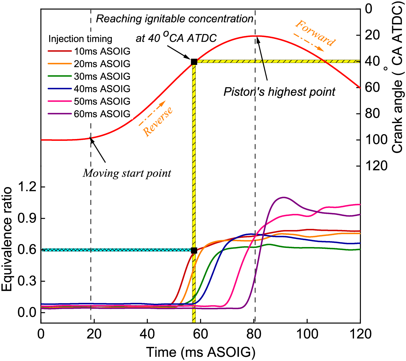
Figure 2: The concentration of the mixture of the second cylinder with varying injection timings
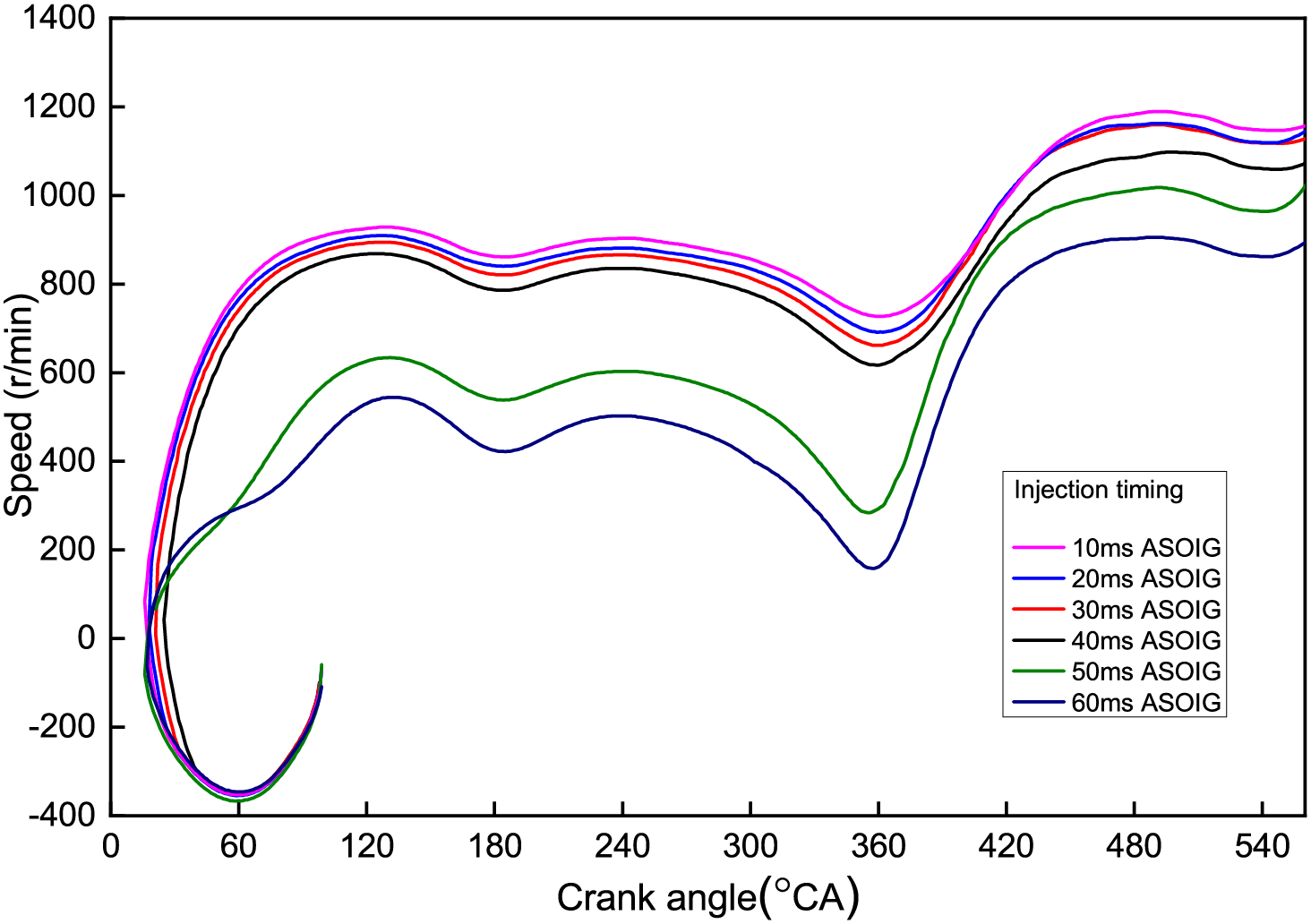
Figure 3: Engine speed of direct-start process with different injection timings for the second cylinder
Fig. 3 depicts the relationship between crankshaft rotation and engine speed during the direct start process of the second cylinder under various fuel injection timings (The third cylinder adopts a fuel injection timing of 200°CA BTDC, an ignition timing of 20°CA BTDC, and an equivalence ratio of 1.0). Within the 10–40 ms range, as the fuel injection is delayed, there is a slight decline in engine speed. However, when injection surpasses 50 ms, due to the delayed heat release and work generation in the second cylinder, the engine’s dynamic performance is severely impacted. Concurrently, the engine speed during the third cylinder’s compression stroke, corresponding to 180–360°CA BTDC, is lower than that during the fourth cylinder’s compression stroke, corresponding to 360–540°CA BTDC, indicating a marked difference in the operational conditions of the third and fourth cylinders.
3.1.2 Effects of the Injection Timing on the Third and Fourth Cylinders’ Start Performance
In the experiment of studying the effect of injection timing on the third and fourth cylinders, the equivalent ratio of fuel injection for the third and fourth cylinders is set to 1.2, and the ignition timing is set to 20°CA BTDC. Fig. 4 shows that the combustion deteriorates under the earlier injection timing, and the peak values of cylinder pressure and heat release rate drop sharply. In contrast, using a later injection timing can achieve better combustion performance. For the third and fourth cylinders, due to different intake conditions, optimization of the injection timing needs to consider the strength of the intake flow and the degree of fuel atomization to ensure better mixing with the air and the formation of a homogeneous combustible mixture. The case with 100°CA BTDC holds the shortest ignition delay for both cylinders, which can be explained as follows. The intake valve happens to be closed at this time; thus, the fuel that has been injected can effectively blend with the air due to the presence of turbulence, resulting in an increase in the concentration of the ignited mixture, leading to relatively optimal combustion. When the injection timing is too early (250°CA BTDC and 300°CA BTDC), due to the slower piston movement and the smaller cylinder volume, a portion of the injected fuel is expelled into the intake manifold. Additionally, the relatively homogeneous mixture formed is pushed into the intake manifold during the early compression stroke, owing to the delayed closing of the intake valve, which affects the total in-cylinder mixture and makes it difficult to ignite. When the injection timing is near the bottom (at 150°CA BTDC and 200°CA BTDC), the intake valve remains open. Although the instantaneous speed of the piston is small, the pressure in the intake manifold surpasses that within the cylinder. Due to intake inertia, the airflow continues to move towards the lower part of the cylinder. Under these conditions, the gas concentration in the lower part of the cylinder is significant and finds it challenging to disperse to the upper part, which affects combustion performance.
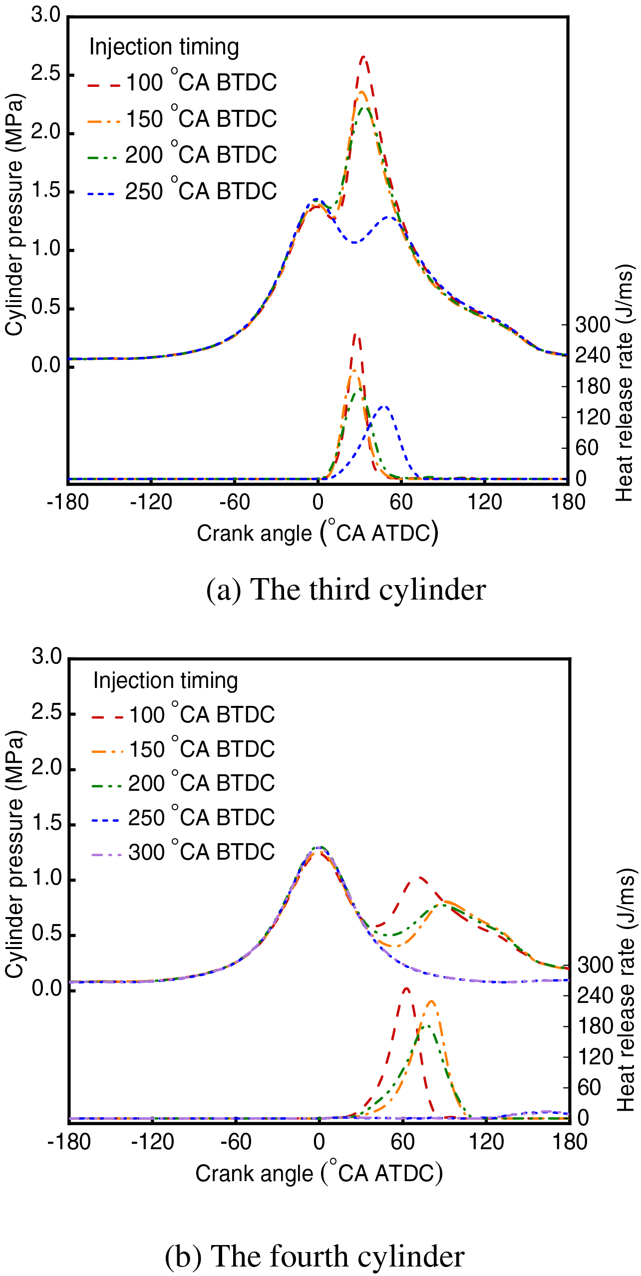
Figure 4: Heat release rate and cylinder pressure of the third and fourth cylinders with different injection timings
Fig. 5 plots the third and fourth cylinders’ top speed at which the engine can accelerate and the maximum rotational speed of the engine with different injection timings. The late fuel injection stage can obtain the highest maximum acceleration and engine speed, and the work capacity is the strongest at this time. While for the early fuel injection affected by the misfire, the movement mainly depends on the inertia generated by the combustion work of the previous ignition cylinder. For late fuel injection near the bottom dead center, due to the comparable word capacity combustion in the late fuel injection strategy, there is no significant difference in maximum acceleration speed and engine speed.
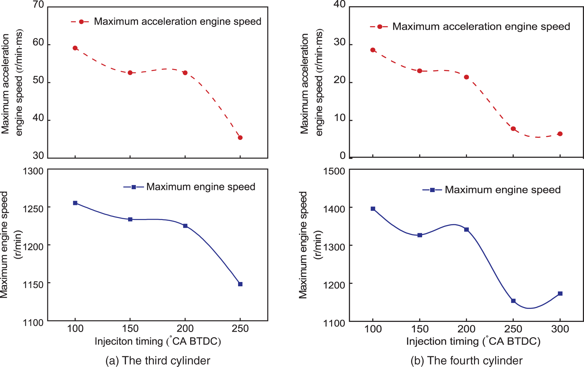
Figure 5: Maximum acceleration engine speed and the maximum engine speed of the third and fourth cylinders with different injection timings
In order to enhance the combustion efficiency and increase the power output of the engine, the intake valves of the third and fourth cylinders should be closed before fuel injection when the injected fuel can be better mixed with the air to increase the work capacity of combustion and produce a better sports effect.
3.2 Effects of the Fuel Equivalence Ratio on Cylinders’ Start Performance
3.2.1 Effects of the Equivalence Ratio on the Second Cylinder’s Start Performance
Due to weak gas movement in the second cylinder, a large amount of fuel adheres to the cylinder wall. Therefore, it is crucial to enrich the fuel injection so that the desired mixture concentration is achieved for ignition. The equivalence ratio mentioned here is obtained based on the actual fuel injection quantity and the amount of air within the cylinder, which surpasses the equivalence ratio of the mixture actually present within the cylinder to achieve better combustion performance. Due to the low temperature during cold starts, fuel evaporation efficiency is poor, so it is necessary to appropriately increase the air-fuel ratio to ensure that the fuel can evaporate fully and form a uniform mixture. This not only helps with ignition but also reduces localized incomplete combustion caused by fuel adhering to the cylinder wall.
Fig. 6 depicts the rate of thermal energy release and the variation in pressure within the cylinder for different equivalence ratios when the injection timing is 10 ms ASOIG. As expected, a higher equivalence ratio induces a faster growth of the two parameters due to the more intense combustion. However, while the equivalence ratio has reached 1.2 or higher, similar combustion performances are achieved even for the sensitive peak value of the heat release rate. At a concentration ratio of 1.2, the rate is approximately 205 J/ms, while at a concentration ratio of 1.5, it is approximately 220 J/ms. This indicates that while higher equivalence ratios lead to faster and more intense combustion, the benefits diminish after reaching a certain point.
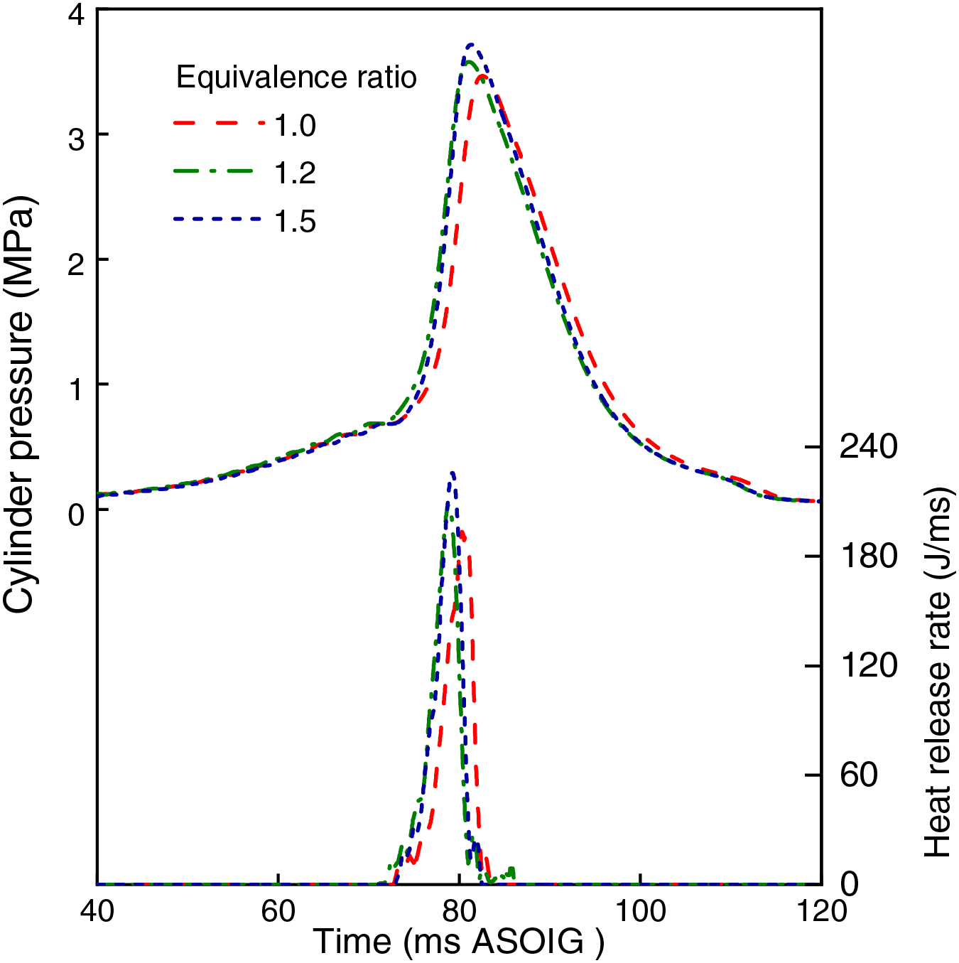
Figure 6: Heat release rate and cylinder pressure of the second cylinder with different equivalence ratios
Similarly, the cylinder pressure increases with a higher equivalence ratio. As the fuel-air mixture becomes richer, the combustion process generates more energy, leading to higher peak pressures in the cylinder. However, like the heat release rate, the increase in cylinder pressure becomes less significant beyond an equivalence ratio of 1.2.
For the motion characteristics, as the equivalence ratio increases, the piston’s highest point lowers, thus indicating the earlier start point of the engine’s forward rotation. The reason lies that under the larger equivalence ratio, the ignition delay is shorter, which contributes to advancing the heat release starting point and increasing the pressure in the cylinder. The caused intense combustion will further impede the piston’s upward movement.
Fig. 7a illustrates the variation in hydrocarbon (HC) emission concentrations with crank angle at equivalence ratios of 1.0, 1.2, and 1.5 after starting forward rotation. During the 0–120°CA ATDC phase, the exhaust valve of the second cylinder has not yet opened. Prior to idling stop, due to incomplete combustion of the mixture under idle conditions, the HC content not discharged in the exhaust manifold during this phase is relatively high. Subsequently, as the second cylinder begins to exhaust, improvements in its combustion lead to a sharp decline in HC concentration towards the later stages of the exhaust stroke. It is noted that under idle conditions, the equivalence ratio is 1.15, thus when employing a stoichiometric ratio of 1.0 during the direct start process, there is a significant decrease in HC concentration after the second cylinder begins to exhaust. Around 320°CA ATDC, the hydrocarbon emissions are notably reduced compared to the original HC value in the exhaust manifold, suggesting that the HC emissions from the second cylinder are better than under idle conditions. After 300°CA ATDC, the first cylinder starts to release, and the concentration gradually increases. Fig. 7b presents the cumulative HC emission mass in the direct start process. Comparing different equivalence ratios, HC emission levels rise with increasing equivalence ratio. Therefore, to achieve improved emission characteristics along with the aforementioned combustion and motion traits, an equivalence ratio of 1.2 is the optimal choice for the second cylinder.
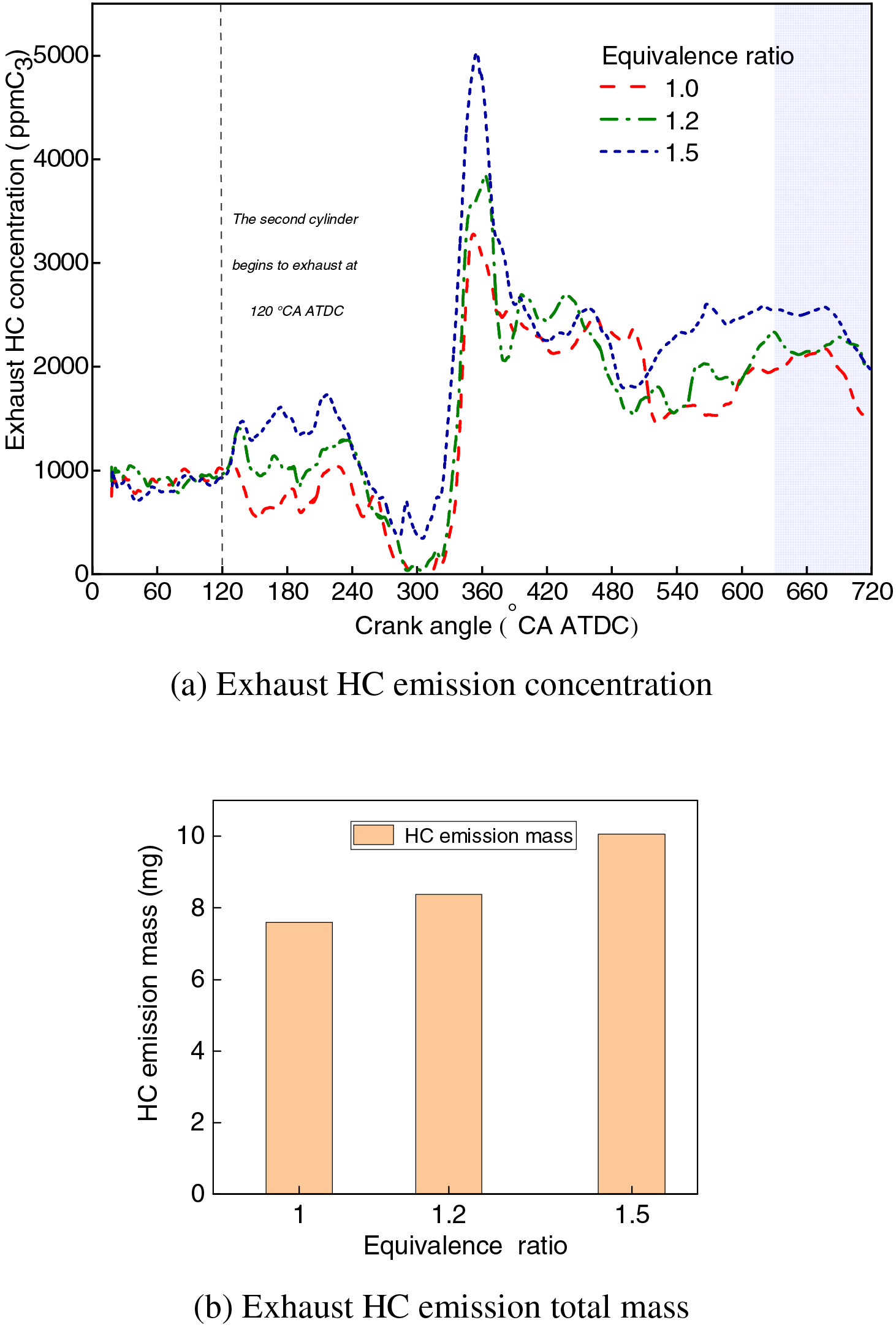
Figure 7: Exhaust HC emission concentration and total mass of the second cylinder with different equivalence ratios
3.2.2 Effects of the Equivalence Ratio on the Third and Fourth Cylinders’ Start Performance
Due to the different intake conditions, the basis for calculating equivalence ratios of the third and fourth cylinder is also different: the former is based on the air content at the shutdown moment, while the latter is on the cylinder displacement. For the third cylinder, since the equivalence ratio is 1.15 at idle speed and under normal engine operation conditions (IMEP = 0.2 MPa @ 2000 r/min) and the air volume is slightly larger than when the engine shuts down, the equivalence ratio range of 1.0–1.6 is researched. For the fourth cylinder, the pressure inside the cylinder during the intake process is inferior to the atmospheric pressure, and thus the intake air is less than that corresponding to the engine displacement. Therefore, the equivalence ratio of 0.8–1.2 is selected to study the start performance of the fourth cylinder. In addition, the experimental configuration involves the adjustment of the injection timing to 200°CA BTDC and ignition timing to 20°CA BTDC. It should be noted that since the direct start process requires control of only the first cycle, the control of fuel injection and ignition is promptly returned to the original engine ECU after the control of the first cycle is completed. When resuming control, the ECU did not receive the accelerator pedal command when it recognized the current engine speed. Therefore, the engine will enter the idle state and adopt the fuel injection timing set for idling. The default fuel injection timing of the engine at idle is 278°CA BTDC, which is significantly different from 100°CA BTDC. To avoid significant performance fluctuations due to an abrupt switch, in the experimental setup of studying the effect of equivalence ratio and ignition timing on the direct start process of the third and fourth cylinders, a compromise fuel injection timing of 200°CA was used for the third and fourth cylinders. Similarly, in Section 3.1.2, when studying the injection timing of the third or fourth cylinder, the other cylinder uses 200°CA BTDC.
Fig. 8 displays the rate of thermal energy release and the variation in pressure within the cylinder of the third and fourth cylinders with different equivalence ratios. Overall, a misfire occurs in both cylinders under the small equivalence ratio (1.0 for the third cylinder; 0.8–1.0 for the fourth cylinder), showing that reducing fuel injection quantity can significantly influence the ignition reliability. The phenomenon is because although air movement is a little stronger in the third and fourth cylinders than in the first two cylinders, better to promote mixture formation, some fuel is still attached to the cylinder wall due to the larger injection pulse width. Consequently, the fuel participating in forming the mixture is still less than the actual injection quantity, decreasing the ignition reliability. As the equivalence ratio increases, there is an enhancement in the combustion process, as evidenced by the more rapid rise and higher peak values of both the heat release rate and cylinder pressure. However, when the equivalence ratio reaches a critical point (1.4 for the third cylinder and 1.2 for the fourth cylinder), the above improvements yielded by increasing fuel injection become weak.
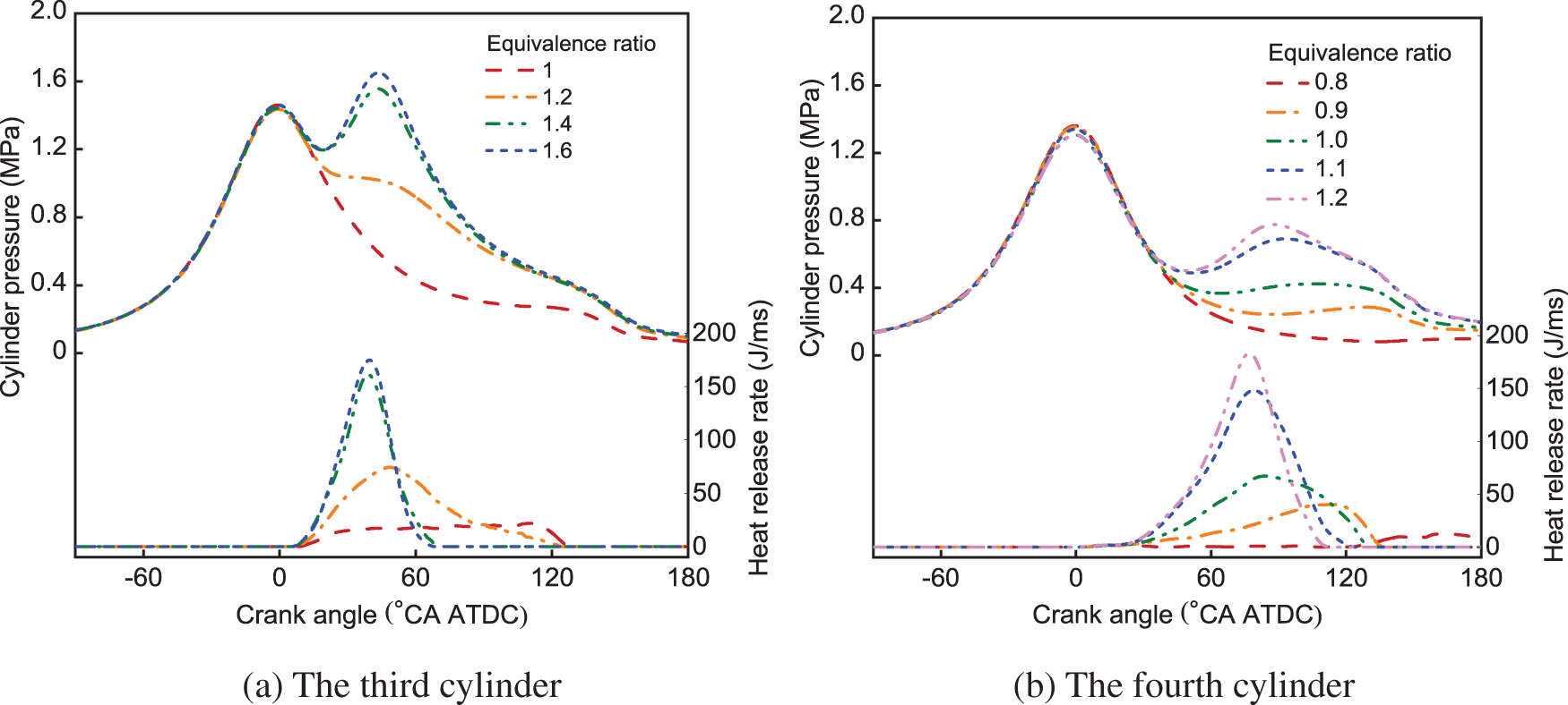
Figure 8: Heat release rate and cylinder pressure of third and fourth cylinders with different equivalence ratios
Furthermore, the combustion characteristics can explain the engine motion characteristics shown in Fig. 9: with an increase in fuel injection mass, both the peak acceleration engine speed and maximum engine speed exhibit an upward trend. Meanwhile, there is a corresponding critical point in their rising trends. Therefore, from the perspective of combustion performance and motion law, increasing fuel injection volume only limitedly improves direct-start performance. On the other hand, excessive fuel injection can cause numerous HC emissions. Therefore, it can be concluded that the optimal equivalence ratio for starting the third cylinder is 1.4, and for the fourth cylinder is 1.2.
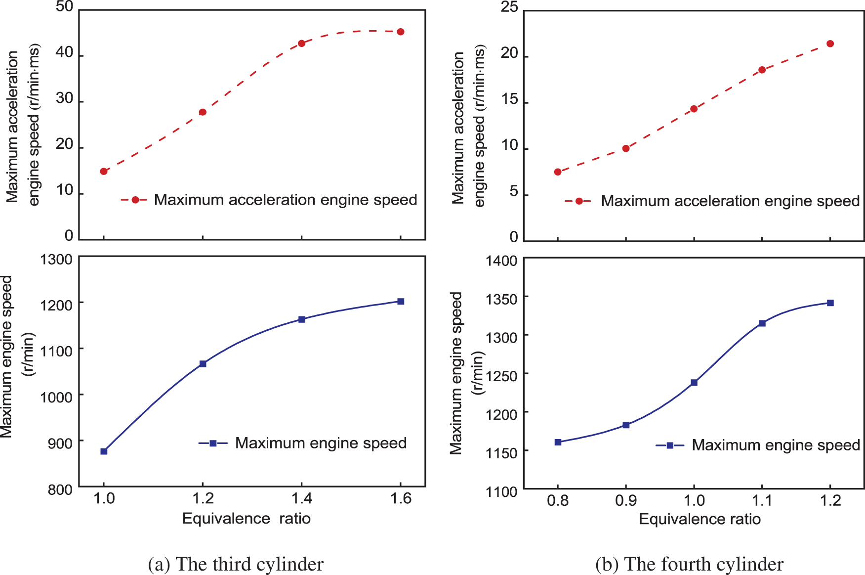
Figure 9: Maximum acceleration speed and maximum engine speed of third and fourth cylinders with different equivalence ratios
3.3 Effects of the Ignition Timing on Cylinders’ Start Performance
3.3.1 Effects of the Ignition Timing on the Second Cylinder’s Start Performance
Ignition timing exerts an impact on multiple aspects of the engine performance, including the initiation of combustion, the work output, and ultimately, the thermal efficiency of the engine. Too early or too late ignition timing can cause significant variations in combustion characteristics. Therefore, ignition timing is crucial for the direct starting of the second cylinder. Otherwise, too early heat release advances the work time, weakens the compression degree, and thus hinders the reverse movement to a certain extent, while too late ignition in the expansion stroke decreases the actual compression ratio and reduces the thermal efficiency. Ignition delay is directly influenced by the efficiency of fuel-air mixture formation, especially in the second cylinder, where the delay in mixture formation leads to increased ignition delay time, affecting the flame propagation speed. In-cylinder turbulence can either aid or hinder flame propagation, depending on its intensity and the distribution of the mixture. Therefore, the guiding principle for adjusting the ignition timing is to place the commencement of the pressure rise close to the piston’s highest moving point and thus yield better combustion and movement effects. In this section, the fuel injection timing is fixed at 10 ms ASOIG to expand the experimental range of the ignition timing. Since the mixture close to the spark plug reaches the concentration suitable for ignition at about 40°CA ATDC and the reverse rotation ends at 20°CA ATDC, the interval of 20–40°CA ATDC is studied. It should be noted that the ignition of the second cylinder occurs during the reverse rotation process. Meanwhile, the equivalence ratio of 1.2 is adopted to ensure ignition reliability.
Figs. 10 and 11 display the second cylinder’s combustion and motion characteristics with the ignition timing of 20°CA ATDC, 30°CA ATDC, and 40°CA ATDC, respectively. Different from the normal positive correlation between ignition timing and combustion performance (Fig. 11), the combustion has completed before the expansion stroke under too early ignition timing (40°CA ATDC) so that the rising cylinder pressure inevitably impedes the piston’s movement as depicted in Fig. 12a, leading to the forward rotation before the reverse motion ends. With the ignition timing delayed to 20°CA ATDC, the combustion completes after the highest point of the piston movement, and the work will start after the end of the reverse movement. As the ignition timing is retarded, the start of the piston movement occurs near the end of the reverse movement, especially since the piston’s motion is already behind the endpoint when the ignition timing is 20°CA ATDC, which does not hinder the compression process of other cylinder caused by the combustion of the first cylinder.
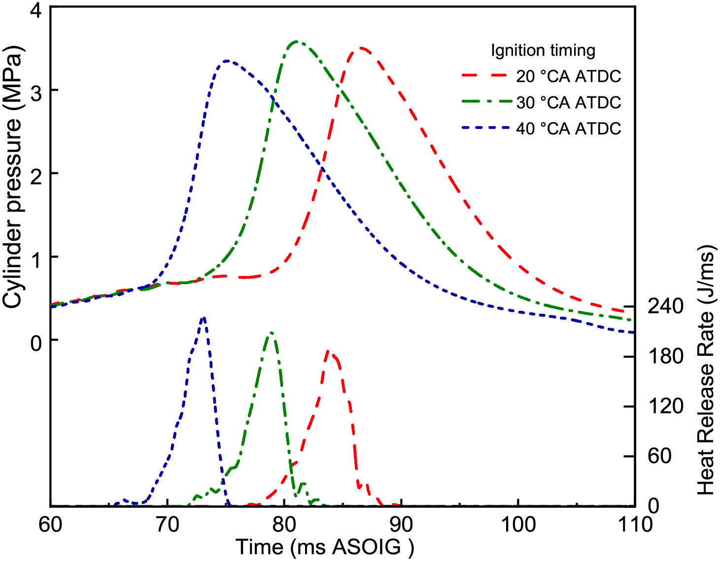
Figure 10: Heat release rate and cylinder pressure of the second cylinder with different ignition timings
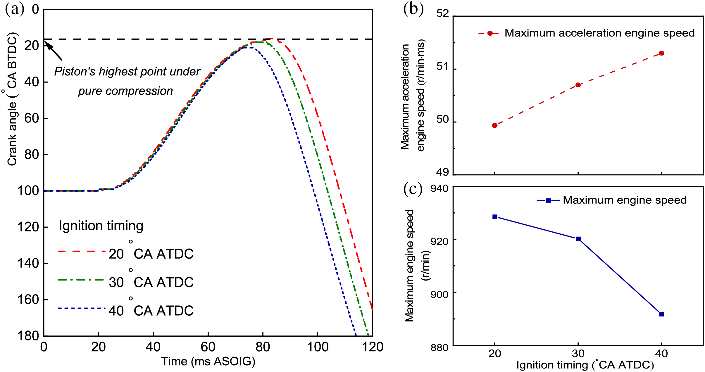
Figure 11: Motion characteristics of the second cylinder with different ignition timings: (a) piston’s movement, (b) maximum acceleration engine speed, (c) maximum engine speed
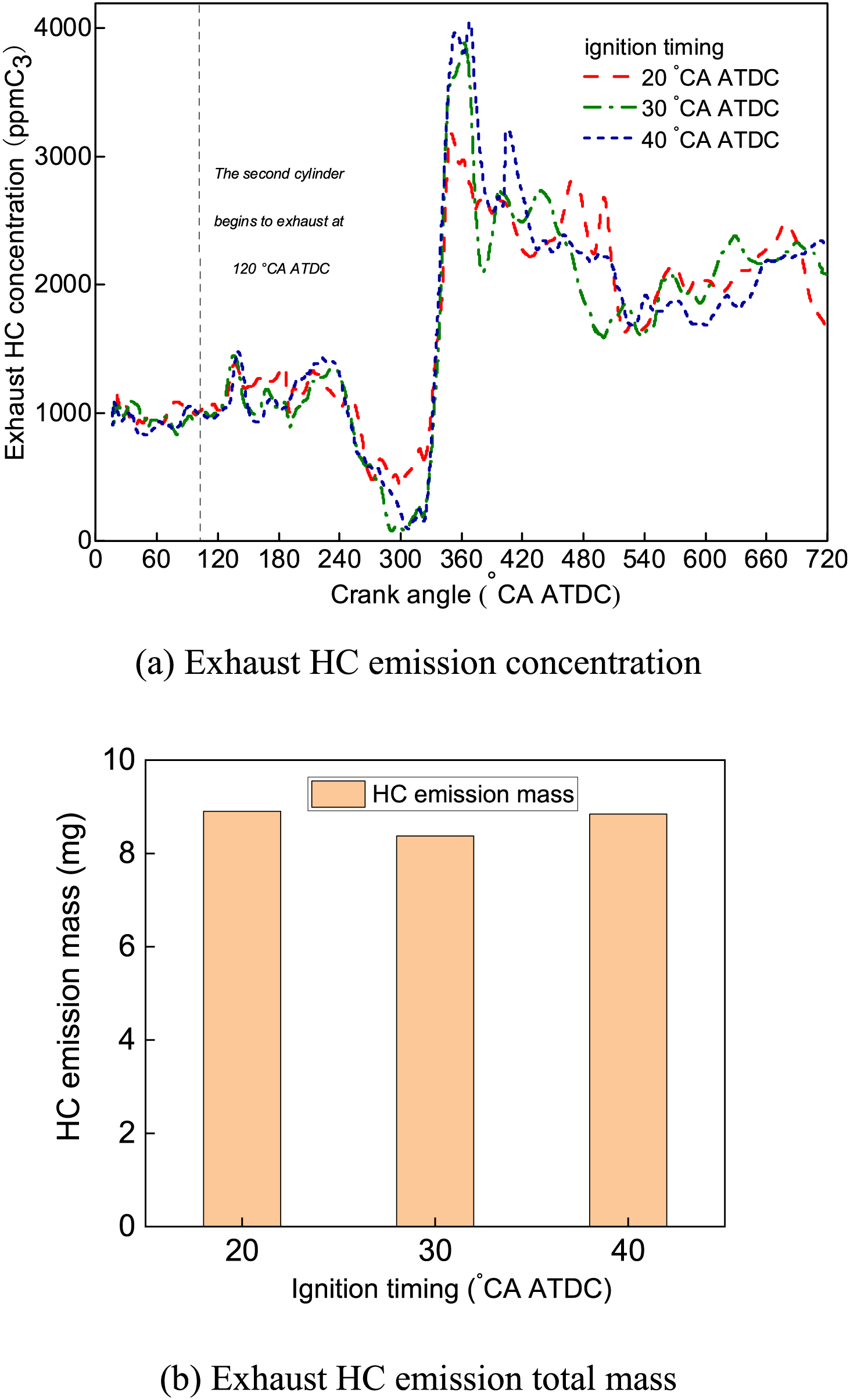
Figure 12: Exhaust HC emission concentration and total mass of the second cylinder with different ignition timings
Furthermore, Fig. 11b,c quantitively compares the work capacity of the second cylinder with different ignition timings. The maximum acceleration exhibits an upward trend as the ignition timing is advanced while the maximum rotational speed value decreases. The reason is that under an earlier ignition timing, the compression resistance is strengthened, necessitating a more substantial expansion force to counteract the heightened compression resistance induced by combustion, resulting in a larger maximum forward acceleration. In addition, based on the work calculation results, the total amount of work is 277 J when the ignition timing is 40°CA ATDC, compared with 295 J and 301 J at 30°CA and 20°CA ATDC, respectively. Hence the ignition timing should be close to the endpoint of the reversal motion and make full use of the reverse motion. Additionally, the higher cylinder pressure after compression causes a reduction in the ignition delay time of the second cylinder relative to the first cylinder. Therefore, the ignition timing should be slightly ahead of the pure compression peak time to achieve the best starting effect.
Fig. 12 plots the HC emissions under different ignition timings. HC emissions at 30°CA ATDC are lower than at 20°CA ATDC and 40°CA ATDC. The explanation for this phenomenon lies in the combustion degree of the fuel-air mixture, which is characterized by the total fuel efficiency (ratio of fuel mass burned to total injected fuel, calculated from the heat release rate and the amount of fuel injected). From the calculation results, the fuel efficiency is comparable in three cases, although the ignition timing of 30°CA ATDC holds the highest fuel efficiency (74.8%), slightly higher than that of 20°CA ATDC (74.5%) as well as 40°CA ATDC (73.4%). Therefore, it can be concluded that the ignition timing for starting the second cylinder can slightly extend forward from the endpoint of the reversal motion. Furthermore, given the analysis above of the combustion and motion characteristics, the ignition timing should be close to the second cylinder’s highest point of compression movement.
3.3.2 Effects of the Ignition Timing on the Third and Fourth Cylinders’ Start Performance
For the third and fourth cylinders that are close to normal engine operation, the ignition timing requires to be further optimization based on the range of 0–40°CA BTDC, given that the engine’s ignition timing at idling conditions and normal operating conditions is 7°CA and 35°CA ATDC, respectively. In addition, the experimental setup is set with an injection timing of 200°CA BTDC and a fuel equivalence ratio of 1.2.
Fig. 13 compares the cylinder pressure as well as the heat release rate of the third and fourth cylinders with different ignition timings. In general, the earlier ignition timing is advantageous for advancing the combustion start point, guiding the combustion phase in proximity to the TDC, thus improving cylinder heat release and pressure. However, it is worth noting that when applying the same ignition timing, the two cylinders manifest different combustion performances. Specifically, the optimal ignition timing for the third cylinder is 20°CA BTDC, where there is a noticeable advancement in the start point of heat release and cylinder pressure, as well as the highest heat release rate (~180 J/ms, compared with ~110 J/ms of 0°CA BTDC), indicating the most efficient combustion effect. In comparison, the combustion performance of the fourth cylinder is improved with more advanced ignition timing; for instance, under the 40°CA BTDC, the heat release starts earlier, with the drastically enhanced heat release rate (~300 J/ms) and cylinder pressure (~2.5 MPa). The above phenomenon stems from the fact that in the direct start of the third cylinder, the rotation speed is low during the intake process (the speed is zero at the beginning of the forward rotation), and the low intake flow rate has a minor contribution to the formation of the mixture. Consequently, unfavorable mixture distribution characteristics arise, with an excessively rich mixture in the lower part of the cylinder and an overly lean mixture in the upper. Favorably, the later ignition timing can partially alleviate this problem by providing sufficient time for the gas to mix up. In this way, the combustion is improved, which directly yields a stronger work capacity. As shown in Fig. 14, the maximum rotational speed and acceleration are the largest. Based on the combustion characteristics for the fourth cylinder, it can be found that the engine speed and acceleration speed increase with the advanced ignition timing, which is identical to the conventional ignition timing control approach. Therefore, the optimal ignition timing for the third cylinder should be 20°CA BTDC, while a more advanced ignition should be adopted for the fourth cylinder.
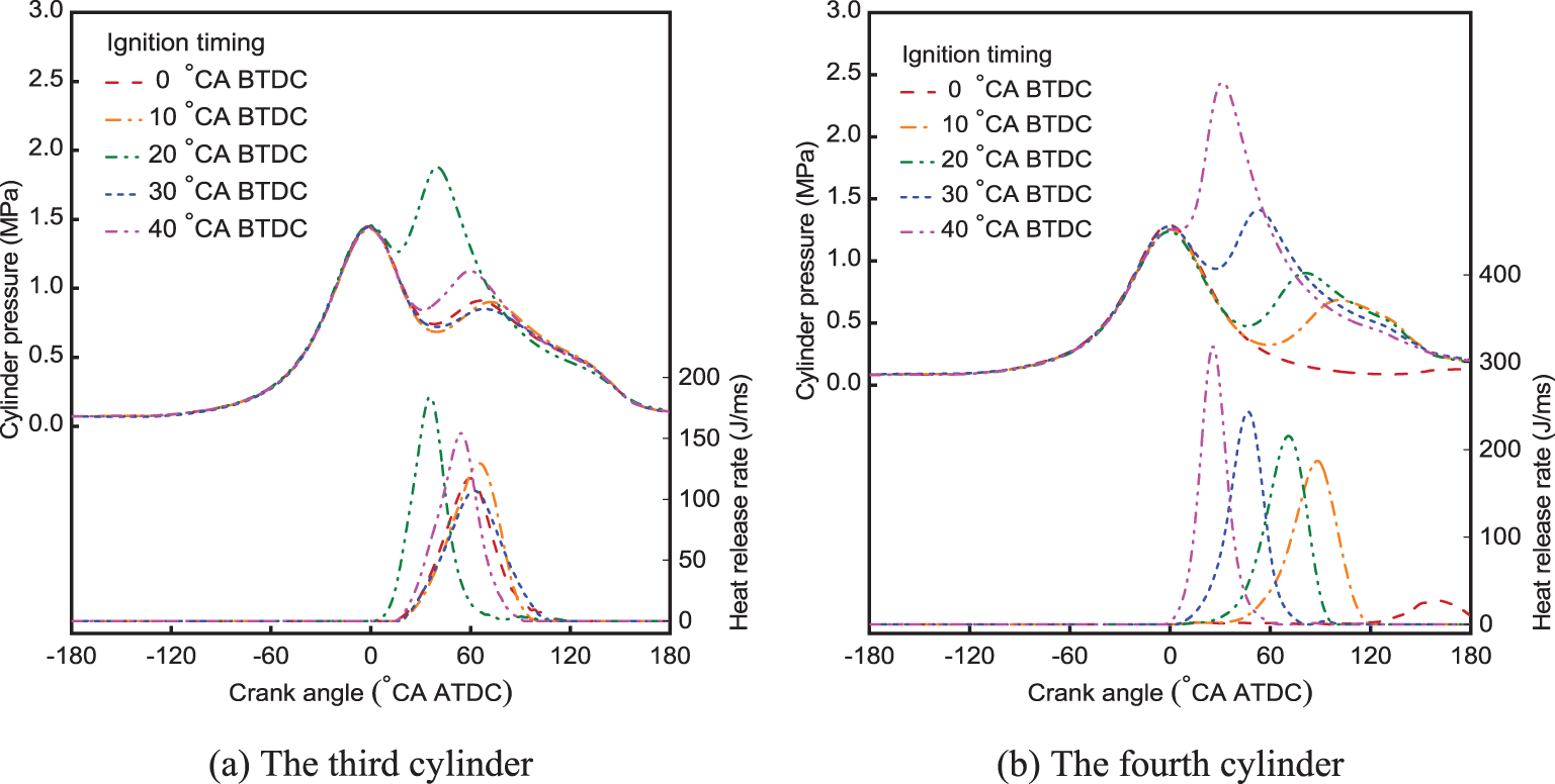
Figure 13: Heat release rate and cylinder pressure of the (a) third and (b) fourth cylinders with different ignition timings
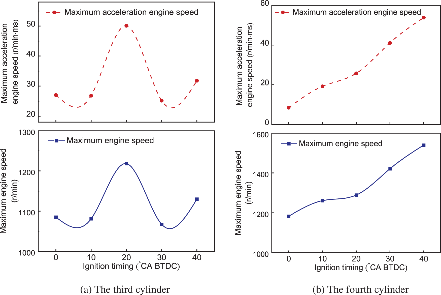
Figure 14: Maximum acceleration engine speed and maximum engine speed of the (a) third and (b) fourth cylinders with different ignition timings
Comprehensively considering the above experimental results, the summary is as follows: the engine speed enhancement ensures the ignition’s reliability and advantages in establishing the rotational inertia force. Due to the relatively less fuel in the cylinder compared to air as well as the lower engine speed through the intake process, the formation of the mixture is more challenging than the idling and normal operation. In such a case, it is necessary to enrich the injected fuel and delay the fuel injection timing to ensure complete utilization of the injected fuel. Moreover, the third cylinder exhibits the best start performance at an ignition timing of 20°CA ATDC, and the fourth cylinder instead should adopt a larger ignition advanced timing to improve the combustion performance.
3.4 Summary of Optimized Injection Parameters of Each Cylinder
Through the above analysis, it can be observed that the control strategy of different cylinders under the direct-start strategy does have specific particularity due to their motion and gas flow characteristics. Through the above analysis, it can be observed that different cylinders have specific characteristics in terms of control strategy under the direct start strategy, which are impacted by their motion and airflow properties.
Due to the fact that the second cylinder completes fuel injection as well as ignition during the reversal process, the control strategy is almost grounded on the combustion and work conditions of the first cylinder. According to our previous research [26,33], the lack of the intake process for the first cylinder and thus the poor mixture mixing degree, the combustion deteriorates considerably and requires significant fuel enrichment, up to 1.6–1.8. The use of a split flow injection strategy also contributes to combustion.
For the second cylinder, although the engine has started to reverse before ignition, and the mixture formation within the cylinder is enhanced in comparison to that of the first cylinder, the injected fuel still demands enrichment due to the weak airflow and the fuel retention, and the equivalence ratio is smaller than the first cylinder. An earlier fuel injection timing can be exploited to ensure a more uniform mixture distribution to get a higher mixture concentration during ignition. Moreover, the ignition timing adjustment depends on the engine movement after the reversal. The optimized ignition timing is close to the highest point of the second cylinder’s piston to reduce the hindrance to the compression process and improve the second cylinder’s thermal efficiency.
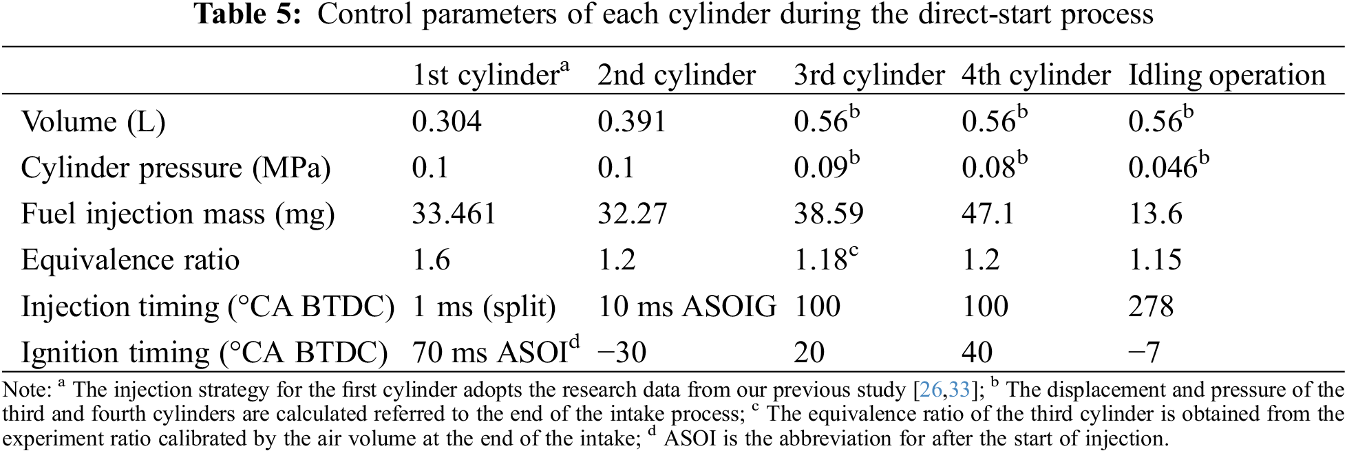
The third and fourth cylinders hold a complete compression stroke and approach the engine’s normal operation process so that the control refers to the engine’s actual operating parameters. Although the high pressure in the intake manifold leads to an increase in the intake gas volume and, consequently the mass of injected fuel, fuel enrichment is still indispensable due to the insufficient evaporation of fuel and intensified wall attachment at low engine speeds. This study’s better fuel equivalence ratio is about 1.2, slightly larger than the idling and normal operating conditions. Besides, the late injection strategy is more applicable for directly starting the third and fourth cylinders; precisely, after the closed angle of the intake valve, making full use of the gas flow capacity in the cylinder and increasing the mixture’s fuel quality improve combustion and fuel efficiency. On the other hand, a more advanced ignition timing should be adopted for the fourth cylinder that approaches normal operating conditions to improve thermal efficiency. In contrast, an ignition timing of approximately 20°CA BTDC is preferred for the third cylinder, or the advanced ignition timing would lower the mixture concentration during ignition, prolong the ignition delay period, and damage the combustion effect. Table 5 summarizes the control parameters of each cylinder in the direct-start process and compares the differences between direct-start, idling operating, and normal operating conditions.
The direct start is a highly transient process, and four cylinders in different strokes have certain particularities in the combustion and movement in the direct-start process, which crucially demands specific control for each cylinder. By conducting a comprehensive analysis of the engine characteristics under varying control parameters, this study presents an integrated optimal control approach for the cylinders. Based on the findings, key findings are as follows:
Injection Timing Optimization: The second cylinder achieves optimal combustion performance with an earlier injection timing (10 ms ASOIG), allowing sufficient time for thorough fuel-air mixing. For the third and fourth cylinders, a delayed injection timing, synchronized with the intake valve closure, was found to be most effective, ensuring better mixture formation and combustion efficiency.
Ignition Timing Optimization: The second cylinder’s ignition timing is best-set close to the highest point of piston movement, enhancing thermal efficiency and minimizing compression hindrance. The third cylinder performs optimally with an ignition timing around 20°CA BTDC, balancing combustion rate with energy utilization. The fourth cylinder benefits from a more advanced ignition timing (around 40°CA BTDC) due to stronger airflow and quicker mixture formation.
Combustion and Emission Performance: Enriching the fuel injection for the second cylinder is necessary to ensure reliable ignition and efficient combustion, given the weaker gas movement. The optimal equivalence ratios were identified as 1.2 for the second and fourth cylinders, and 1.4 for the third cylinder, balancing combustion efficiency and emissions. Additionally, interference between intake flows in different cylinders also leads to combustion variations between cycles, especially when shared intake and exhaust manifolds are used.
Fuel Atomization and In-Cylinder Airflow Dynamics: Fuel injection dynamics and in-cylinder flow patterns have a significant impact on combustion and ignition during the direct-start process. Particularly under low-speed and cold-start conditions, the quality of fuel atomization, the speed of mixture formation, and the distribution of airflows within the cylinders are critical to ensuring stable combustion.
These findings provide a comprehensive strategy for optimizing the direct-start process in GDI engines, contributing to improved engine performance and reduced emissions during start-up.
Acknowledgement: None.
Funding Statement: This work was supported by the National Natural Science Foundation of China (grant number 51576129).
Author Contributions: The authors confirm contribution to the paper as follows: study conception and design: Tao Chen, Zhengyu Du, Lei Shi; data collection: Tao Chen, Zhengyu Du, Maoyu Xiao, Zhe Zhang, Zihan Liu; analysis and interpretation of results: Tao Chen, Zhengyu Du, Zihan Liu; draft manuscript preparation: Tao Chen, Zihan Liu, Maoyu Xiao, Zhe Zhang. All authors reviewed the results and approved the final version of the manuscript.
Availability of Data and Materials: The datasets generated during the current study are not publicly available due to the confidentiality policy of the institution, but are available from the corresponding author on reasonable request.
Ethics Approval: Not applicable.
Conflicts of Interest: The authors declare no conflicts of interest to report regarding the present study.
References
1. Nguyen YL, Le AT, Nguyen DK, Nguyen DV, Nguyen CD. A study on emission and fuel consumption of motorcycles in idle mode and the impacts on air quality in Hanoi, Vietnam. Int J Urban Sci. 2021;25(4):522–41. doi:10.1080/12265934.2020.1871059. [Google Scholar] [CrossRef]
2. Tan P, Duan L, Li E, Hu Z, Lou D. Experimental study on the temperature characteristics of a diesel particulate filter during a drop to idle active regeneration process. Appl Therm Eng. 2020;178(2):115628. doi:10.1016/j.applthermaleng.2020.115628. [Google Scholar] [CrossRef]
3. Wang Z, Ding H, Wyszynski ML, Tian J, Xu H. Experimental study on diesel fuel injection characteristics under cold start conditions with single and split injection strategies. Fuel Process Technol. 2015;131(9):213–22. doi:10.1016/j.fuproc.2014.10.003. [Google Scholar] [CrossRef]
4. Zhang C, Ficenec K, Kotz A, Kelly K, Sonntag D, Fulper C, et al. Developing a heavy-duty vehicle activity database to estimate start and idle emissions. Transp Res Part D. 2022;105(10):103251. doi:10.1016/j.trd.2022.103251. [Google Scholar] [CrossRef]
5. Ge J, Wu G, Yoo B, Choi N. Effect of injection timing on combustion, emission and particle morphology of an old diesel engine fueled with ternary blends at low idling operations. Energy. 2022;253(15):124150. doi:10.1016/j.energy.2022.124150. [Google Scholar] [CrossRef]
6. Paranahyba DAA, Yochihiro FH. An efficiency and robustness analysis of warm-start mathematical models for idle and waiting times optimization in the flow shop. Comput Indust Eng. 2022;166(3):107976. doi:10.1016/j.cie.2022.107976. [Google Scholar] [CrossRef]
7. Fang L, Lou D, Hu Z, Tan P, Zhang Y, Yang R. Study on the First-Firing-Cycle combustion characteristics of high-altitude and low-temperature environments during diesel engine cold start. Fuel. 2022;322(15):124186. doi:10.1016/j.fuel.2022.124186. [Google Scholar] [CrossRef]
8. Wu B, Zi Z, Zou X, Li J, Jin S. Effect of intake temperature and coolant temperature with injection strategy on gasoline compression ignition combustion stability under the idle condition. Int J Engine Res. 2023;24(3):1239–50. doi:10.1177/14680874221081666. [Google Scholar] [CrossRef]
9. Matsuura M, Korematsu K, Tanaka J. Fuel consumption improvement of vehicles by idling stop. In: SAE technical paper; 2004. 2004-01-1896. [Google Scholar]
10. Zhang P, He J, Chen H, Zhao X, Geng L. Improved combustion and emission characteristics of ethylene glycol/diesel dual-fuel engine by port injection timing and direct injection timing. Fuel Process Technol. 2019;199:106289. doi:10.1016/j.fuproc.2019.106289. [Google Scholar] [CrossRef]
11. Ma Z, Fu T, Wang Y, Zhao W, Zhang L. Research on the effects of idling start-stop function on light vehicles fuel consumption and emission under different cycle conditions. E3S Web Conf. 2021;268(8):01030. doi:10.1051/e3sconf/202126801030. [Google Scholar] [CrossRef]
12. Shi Y, Dong J, Li Q, Zheng Q. Design of starting motor test-bed for vehicle. J Phys: Conf Ser. 2022;2383(1):012025. doi:10.1088/1742-6596/2383/1/012025. [Google Scholar] [CrossRef]
13. Bishop J, Nedungadi A, Ostrowski G, Surampudi B, Armiroli P, Taspinar E. An engine start/stop system for improved fuel economy. In: SAE technical paper; 2007. 2007-01-1777. [Google Scholar]
14. Wellmann T, Govindswamy K, Orzechowski J, Srinivasan S. Influence of automatic engine stop/start systems on vehicle NVH and launch performance. SAE Int J Engines. 2015;8(4):1938–46. doi:10.4271/2015-01-2183. [Google Scholar] [CrossRef]
15. Zhang Q, Wang X, Song G, Li M. Performance and emissions of a pilot ignited direct injection natural gas engine operating at slightly premixed combustion mode. Fuel Process Technol. 2022;227(2):107128. doi:10.1016/j.fuproc.2021.107128. [Google Scholar] [CrossRef]
16. Zhu R, Fu Y, Wang L, Hu J, He L, Wang M, et al. Effects of a start-stop system for gasoline direct injection vehicles on fuel consumption and particulate emissions in hot and cold environments. Environ Pollut. 2022;308:119689. doi:10.1016/j.envpol.2022.119689. [Google Scholar] [PubMed] [CrossRef]
17. Chen Z, Liao B, Yu Y, Qin T. Effect of equivalence ratio on spark ignition combustion of an air-assisted direct injection heavy-fuel two-stroke engine. Fuel. 2022;313(10):122646. doi:10.1016/j.fuel.2021.122646. [Google Scholar] [CrossRef]
18. Liu Z, Liu J. Effect of altitude conditions on combustion and performance of a turbocharged direct-injection diesel engine. Proc Inst Mech Eng Part D: J Automobile Eng. 2022;236(4):582–93. doi:10.1177/09544070211026204. [Google Scholar] [CrossRef]
19. Fan L, Wen L, Bai Y, Lan Q, Xu J, Gu Y. Research on the correlation between fuel injection quantity and key structural parameters for the fuel system of marine diesel engines. Proc Inst Mech Eng Part C: J Mech Eng Sci. 2021;235(24):7385–98. doi:10.1177/09544062211017935. [Google Scholar] [CrossRef]
20. Lee S, Kim G, Bae C. Effect of injection and ignition timing on a hydrogen-lean stratified charge combustion engine. Int J Engine Res. 2022;23(5):816–29. doi:10.1177/14680874211034682. [Google Scholar] [CrossRef]
21. Sun W, Hong W, Xie F, Su Y. Study on optimization of control parameters for the second cycle during forward rotation direct-start process at a GDI engine. Appl Mech Mater. 2015;742:551–5. doi:10.4028/www.scientific.net/AMM.742.551. [Google Scholar] [CrossRef]
22. Kramer U, Badke K, Wytrykus F, Wissussek D. Experimental determination of the oxygen concentration in the start cylinder of a direct started engine. SAE Trans. 2004;1:259–68. doi:10.4271/2004-01-0544. [Google Scholar] [CrossRef]
23. Kulzer A, Laubender J, Lauff U, Mößner D, Sieber U. Direct start: from model to demo vehicle. MTZ Worldw. 2006;67(9):12–5. doi:10.1007/BF03227868. [Google Scholar] [CrossRef]
24. Zhong B, Hong W, Xie F, Su Y, Li X. Effect of initial start conditions on combustion and rotation characteristics of first firing cycle during direct-start process for a GDI engine. Appl Therm Eng. 2017;127:116–26. doi:10.1016/j.applthermaleng.2017.08.011. [Google Scholar] [CrossRef]
25. Xie F, Hong W, Su Y, Wang Q, Zhu H, Gu C. Direct start of a gasoline direct-injection engine without a starter. Proc Inst Mech Eng Part D: J Autom Eng. 2016;230(4):491–502. doi:10.1177/0954407015587403. [Google Scholar] [CrossRef]
26. Shi L, Xiao M, Deng K. Study on the combustion and hydrocarbon emission characteristics of direct injection spark-ignition engines during the direct-start process. Energy Convers Manag. 2015;103:191–9. doi:10.1016/j.enconman.2015.06.031. [Google Scholar] [CrossRef]
27. Choi M, Park S. Optimization of multiple-stage fuel injection and optical analysis of the combustion process in a heavy-duty diesel engine. Fuel Process Technol. 2022;228:107137. doi:10.1016/j.fuproc.2021.107137. [Google Scholar] [CrossRef]
28. Jose J, Mittal M, Ramesh A. Development of a small-bore gasoline direct-injection engine, and enhancement of its performance using multiple-injection strategies. SAE Int J Engines. 2020;14(1):115–34. doi:10.4271/03-14-01-0008. [Google Scholar] [CrossRef]
29. Lee Z, Kim T, Park S, Park S. Review on spray, combustion, and emission characteristics of recent developed direct-injection spark ignition (DISI) engine system with multi-hole type injector. Fuel. 2020;259(4):116209. doi:10.1016/j.fuel.2019.116209. [Google Scholar] [CrossRef]
30. Zhang J, Shen T, Marino R. Model-based cold-start speed control scheme for spark ignition engines. Control Eng Pract. 2010;18(11):1285–94. doi:10.1016/j.conengprac.2010.01.010. [Google Scholar] [CrossRef]
31. Prucka JM. Development of an engine stop/start at idle system. In: SAE technical paper; 2005. 2005-01-0069. [Google Scholar]
32. Heywood J. Internal combustion engine fundamentals. New York: McGraw-Hill Education; 2018. [Google Scholar]
33. Guo W, Xiao M, Zhang Z, Wang Y, Shi L, Deng K. Effects of multiple injections on the combustion and hydrocarbon emission characteristics of the start cylinder in direct-start process. Fuel. 2022;320(20):123851. doi:10.1016/j.fuel.2022.123851. [Google Scholar] [CrossRef]
Cite This Article
 Copyright © 2025 The Author(s). Published by Tech Science Press.
This work is licensed under a Creative Commons Attribution 4.0 International License , which permits unrestricted use, distribution, and reproduction in any medium, provided the original work is properly cited.
 Downloads
 Citation Tools