
 Submit a Paper
 Propose a Special lssue
 Open Access
ARTICLE

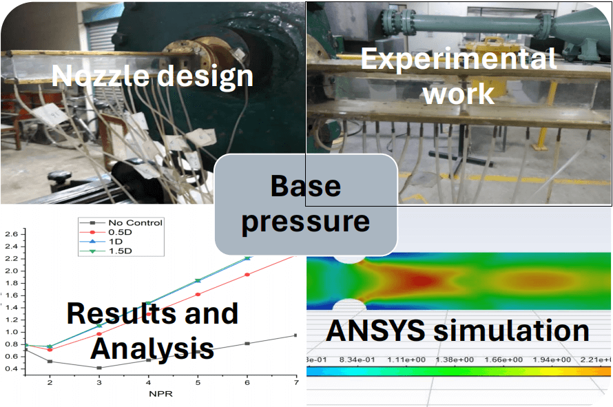
Base Pressure Control with Semi-Circular Ribs at Critical Mach Number
1 School of Aerospace Engineering, Universiti Sains Malaysia, Penang, 11600, Malaysia
2 Department of Mechanical and Aerospace Engineering, Faculty of Engineering, International Islamic University Malaysia, Kuala Lumpur, 59000, Malaysia
3 Department of Engineering Management, College of Engineering, Prince Sultan University, P.O. Box 66833, Riyadh, 11586, Saudi Arabia
* Corresponding Authors: Mohammed Nishat Akhtar. Email: ; Abdul Aabid. Email:
(This article belongs to the Special Issue: Computational Fluid Dynamics: Two- and Three-dimensional fluid flow analysis over a body using commercial software)
Fluid Dynamics & Materials Processing 2024, 20(9), 2007-2028. https://doi.org/10.32604/fdmp.2024.049368
Received 04 January 2024; Accepted 21 May 2024; Issue published 23 August 2024
 View Full Text
 Download PDF
Abstract
When better fuel-air mixing in the combustion chamber or a reduction in base drag are required in vehicles, rockets, and aeroplanes, the base pressure control is activated. Controlling the base pressure and drag is necessary in both scenarios. In this work, semi-circular ribs with varying diameters (2, 4, and 6 mm) positioned at six distinct positions (0.5D, 1D, 1.5D, 2D, 3D, and 4D) inside a square duct with a side of 15 mm are proposed as an efficient way to apply the passive control technique. In-depth research is done on optimising rib size for various rib sites. According to this study, the base pressure rises as rib height increases. Furthermore, the optimal location for the semi-circular ribs with a diameter of 2 mm is at 0.5D. The 1D location appears to be optimal for the 4 mm size as well. For the 6 mm size, however, the 4D position fills this function.Graphic Abstract
Keywords
Nomenclature
| CFD | Computation fluid dynamics |
| CD | Convergent divergent |
| D | Diameter of duct |
| FVM | Finite volume method |
| L/D | Length-to-diameter ratio |
| M | Mach number |
| NPR | Nozzle pressure ratio |
| P0 | Stagnation pressure in the settling chamber |
| Pa | Atmospheric pressure |
| Pb/Pa | Non-dimensional base pressure |
The last few decades have seen the emergence of an intriguing new subject of study: turbulent base flows. The blunt bases of projectiles, the fuselage of airplanes, the blunt bases of shells, etc., commonly have low or sub-atmospheric pressure. The turbulent boundary layer forms further downstream when the base flows come together at the duct wall and split the shear layer from the step pointing rearward [1]. When this phenomenon occurs at the sonic Mach number, it becomes a fascinating and demanding research topic. The flow becomes complicated and chaotic around the base. A literature survey indicates that base drag accounts for 60%–70% of the net drag in the aerospace vehicle at transonic Mach number.
By increasing the base pressure and lowering the base drag, this study seeks to reduce overall drag. The other drag components, such as wave drag due to the presence of the shock waves and the viscous effects of the skin friction drag, cannot be significantly reduced as they will be present by default to achieve the mission requirement. Controlling and regulating the base pressure is one strategy. Two different kinds of controls exist. One involves passive control, and the other involves active control. Cavities, static cylinders, dimples, spikes, splitter plates, and other passive device types are used [2]. Using flow actuators to control the base pressure actively is one option. Suction or blowing can also be used as active controls [3]. This work uses semi-circular ribs with an area ratio of 2.25 and a sonic Mach number of 15 mm for the duct side to adjust base pressure passively.
Rathakrishnan employed rectangular-shaped ribs as a passive control mechanism for the first time in 2001 [4]. However, he used a circular duct with a 25 mm diameter and five rectangular ribs with aspect ratios of 3:1, 3:2, and 3:3 to examine the impact on flow development at sonic Mach number. He concluded that the 3:3 ratio is the most successful in raising the pressure in the recirculation zone and decreasing the base drag. However, a rib with a 3:1 aspect ratio should be employed if the goal is to lower the base pressure. It is widely known that the combustion chamber of a propulsion system must have a minimal base pressure for the fuel and air to mix more effectively, creating the most effective propulsion system possible. Because the boundary layer that extends from the nozzle exit joins the base’s downstream wall with its long extension, his experimental results also show that the base pressure is at its lowest for an L/D ratio of 4 when the pressure ratio is 1.171. Depending on its distance from the base region and the Mach number at the nozzle exit, it is found that the primary vortex created at the base region impacts the base pressure. The primary vortex’s strength determines the base zone’s low-pressure level. The flow is reversed because of the low-pressure area that the vortex produces. By dividing the two flows, passive control can be applied as ribs. Tests were conducted on annular ribs using a range of L/D ratios from 0.5D to 6D and nozzle pressure ratios (NPRs) from 1 to 7 at subsonic to sonic Mach numbers [5]. The base pressure rises as NPR grows because L/D = 0.5 for NPR 3.
The research encompasses a wide range of fluid dynamics and aerodynamics studies. In one investigation, the team explored the effect of micro jets on flow development within the duct operating at supersonic Mach numbers [6]. Another aspect of their work is developing a cost-effective technique for reducing base drag [7]. Furthermore, they analyzed base pressure changes occurring in internal and external suddenly expanded flows using CFD techniques [8]. In parallel, their research also explored the effects of micro-jets on the flow field of ducts with abrupt expansions [9], examined the impact of control mechanisms on the flow development within ducts at Mach 1.2 with specific area ratios [10], and carried out CFD analyses to investigate the influence of splitter plates on bluff bodies [11]. The team also conducted numerical simulations to study CD nozzles and their sensitivity to duct length variations [12]. This comprehensive body of research contributes significantly to our understanding of fluid dynamics and its applications in various engineering and aerodynamic contexts.
A splitter plate was employed by Jodai et al. [13] as a passive control close to the trailing edge of a flat plate in a turbulent boundary layer—half to five times the plate’s trailing edge thickness made up the splitter plate’s length. Base pressure at the trailing edge was measured. It was estimated on a flat plate in the turbulent boundary layer when the pressure gradient was zero. The mean velocity rose close to the turbulent boundary layer’s trailing edge without the splitter plate. The base pressure was raised by the splitter plate, though, and this caused an average velocity spreading that resembled a fully established turbulent boundary layer. Reedy et al. [14] used a splitter plate to study supersonic flow at Mach 2.49. The blunt axisymmetric body is in front of the splitter plate. The base pressure was altered due to the three-quarter, one-third, and one-fourth cylinder splitters’ impact on the near-wake flow, changing the base drag. The splitter plate produces up to 39% less base drag. A passive rectangular flap suggested by Siddiqui et al. [15] was put on a 35 Ahmed body to lessen drag. In their situation, a 100 flap angle decreased the drag by 14%. According to Mariotti et al. [16], the region of the spanwise wake experienced a 9.7% decrease in drag. Capone et al. [17] claimed a drag decrease on square-backed cars using horizontal and vertical deflectors. A reduction in drag was achieved by altering the circular vortex at the base [18]. Road vehicles’ aerodynamic drag is being decreased by developing several active and passive control systems [19]. Abedin et al. [20] examined the aerodynamic drag of cars and discovered that using active, passive, and combination approaches resulted in drag reductions of 20%, 21.2%, and 30%. Mehta [21] investigated how aerospike affected the satellite launch vehicle.
At transonic and low supersonic speeds (0.8 M to 3.0 M), this forward-facing aerospike significantly reduces aerodynamic drag when mounted to the payload fairing. The payload fairing significantly impacts the payload’s flow field and lowers aerodynamic drag at sonic and supersonic Mach numbers. With and without aero spikes, the numerical simulation was run on Mach numbers ranging from 0.8 M to 3.0 M. The flow field was significantly affected by a forward-facing aerospike mounted to the payload fairing of a satellite launch vehicle. The results show that it decreased aerodynamic drag at low supersonic and sonic Mach numbers. At Mach 1.9, a flow separation control over a contour bump was investigated experimentally by Lo et al. [22]. Their study concluded that using a high jet total pressure increases the effectiveness of this flow control method. Lo et al. [23] have experimentally explored the flow patterns along the stream and span over three rounded contour bumps using different flow control algorithms implemented in a Mach 1.3 freestream. It was found that the blowing jet pushed the boundary layer downward and impeded the production of the spanwise vortices in the bump valley, forming a minor re-circulating bubble downstream of the bump crest. Khan et al. [24] studied the impact of ribs for suddenly expanded flow at Mach unity. Their study found that at sonic and supersonic Mach numbers, the base pressure will increase significantly when the flow is under the favorable pressure gradient. Another study by Khan et al. [25] proved that the base pressure will increase whenever the nozzle is under-expanded. Nurhanis et al. [26] did a numerical simulation on the effect of the cavity with sudden expansion. They found that cavity diameter, position, and NPR all affect base pressure. Passive in the shape of an 18 mm-diameter circular duct that simulates a rectangular rib. According to this study, placing the rib at 4D improves base pressure [27]. Furthermore, base heating, launch vehicle stage separation, and the vortex motion/ignition mechanism of subsonic and supersonic turbulent jet flames have all been used to identify the flow field and its control mechanism [28,29].
From the above review, we conclude that even though researchers tried to control the base pressure, no experimental or numerical study was conducted using a semi-circular rib. Hence, in this research, an attempt is made to employ semi-circular ribs as a passive control mechanism for CFD simulation for duct side of 15 mm for semi-circular ribs positions at 0.5D, 1D, 1.5D, 2D, 3D, and 4D for semi-circular rib diameters 2, 4, and 6 mm.
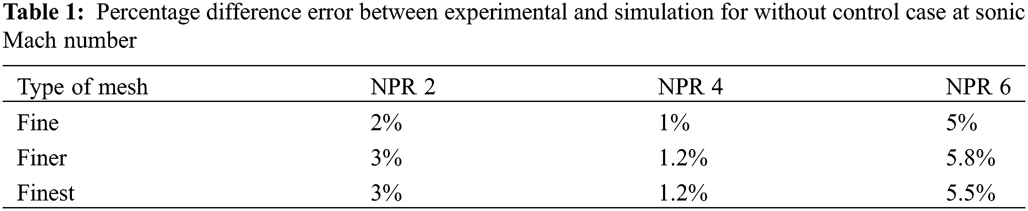
ANSYS Fluent (2020) was used to simulate the flow from the converging nozzle and the duct for various semi-circular rib locations to arrive at an optimum size and locations of the passive controls in the form of semi-circular ribs. A rectangular structured mesh is employed to record the variations in velocity. Fig. 1 depicts the results of a test for mesh independence using elements of varying sizes. Increasing the mesh element sizes beyond the fine mesh’s threshold produces the same result. The element size chosen for the simulation is Fine as it gives the same result as Finer and Finest with a reduction in the overall run time to thirty minutes of the simulation. Fig. 2 shows the mesh of the converging nozzle and duct without rib. Table 1 below gives the difference between experimental and simulation without control case at sonic Mach number. The results are validated with the experimental results at sonic Mach number without control case for NPR 2, NPR 4, and NPR 6. From the validation, it is seen that all the results are within 10% error. Hence, the validation is acceptable. A square duct of side 28 mm and a square nozzle with the same dimension for simulation are considered for validation. The computation model used for simulation has the exact dimensions of the nozzle that are considered for validation. The square duct side used for simulation is 15 mm. This type of computational model is considered under this study for such a small square duct side of 15 mm with three different types of passive control like a semi-circular rib of diameter 2, 4, and 6 mm at six different locations, namely 0.5D, 1D, 1.5D, 2D, 3D and 4D is not considered till this date.
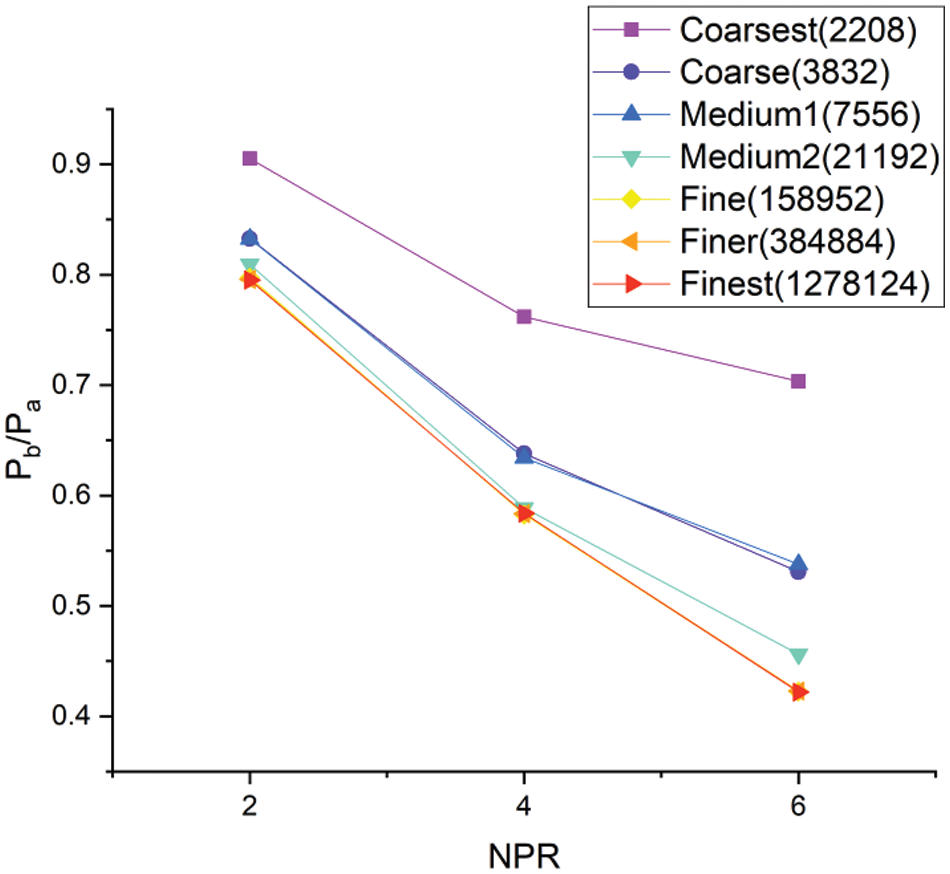
Figure 1: Mesh independence check
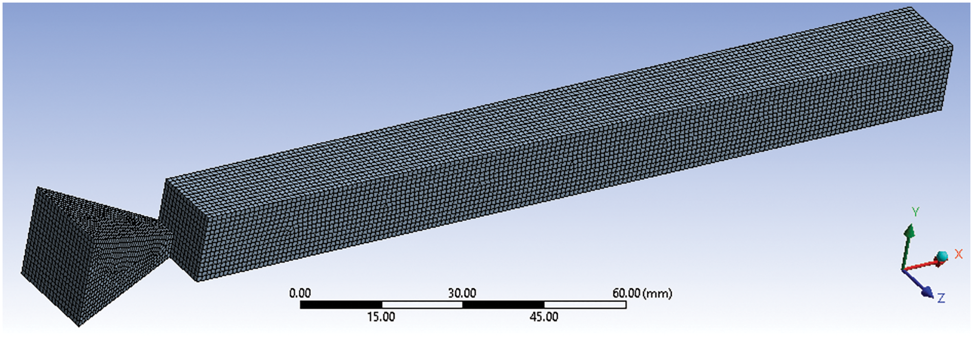
Figure 2: The meshing of the sonic nozzle without the control case
The following assumptions are considered to illustrate the flow inside the duct:
i) When the base pressure is recorded using DAQ, the flow is believed to be stable.
ii) The turbulent flow is considered due to the significant turbulent viscous dissipation effects.
iii) The fluid’s viscosity depends on temperature and is compressible.
iv) At atmospheric pressure, the flow leaves the duct.
v) The typical k-epsilon turbulence model was used by Mariotti et al. [16] to simulate the interior flow. For this reason, the conventional k-epsilon turbulence model is applied to the situation. Sutherland’s three-coefficient viscosity model is represented as:
A reference viscosity value in kg/m-s is represented as
The mass balance equation reads:
where V is the fluid velocity.
The momentum balance equation reads:
where
The total energy equations reads:
where
Because of its economy, robustness, and adequate accuracy, the k-ε turbulence model is extensively used in many flow simulations for an internal flow. The Ansys Fluent software includes this study’s k-epsilon (
The term
where
3.2 Validation of CFD Results with Experimental Implementation
The experiment utilizing an open jet facility and apparatus is depicted in Fig. 3. The reservoir pressure is transported via a settling chamber equipped with flow conditioning equipment, and based on the Mach number, it is enlarged. For a constant diameter of the larger duct, the expansion is achieved by convergent and convergent-divergent square nozzles of various Mach values. The temperature within the settling chamber and the building were the same. The environment within the laboratory remained still when the jet was sent into the broader duct with a greater diameter. Pressure transducers measure the pressure within the tube at the base and along the duct wall. Air is transported from the storage tank to the settling chamber via the mixing length. A threaded connection is used to secure the nozzle to the settling chamber. The pressure, P0, in the settling chamber was maintained at the required levels with a pressure control valve.
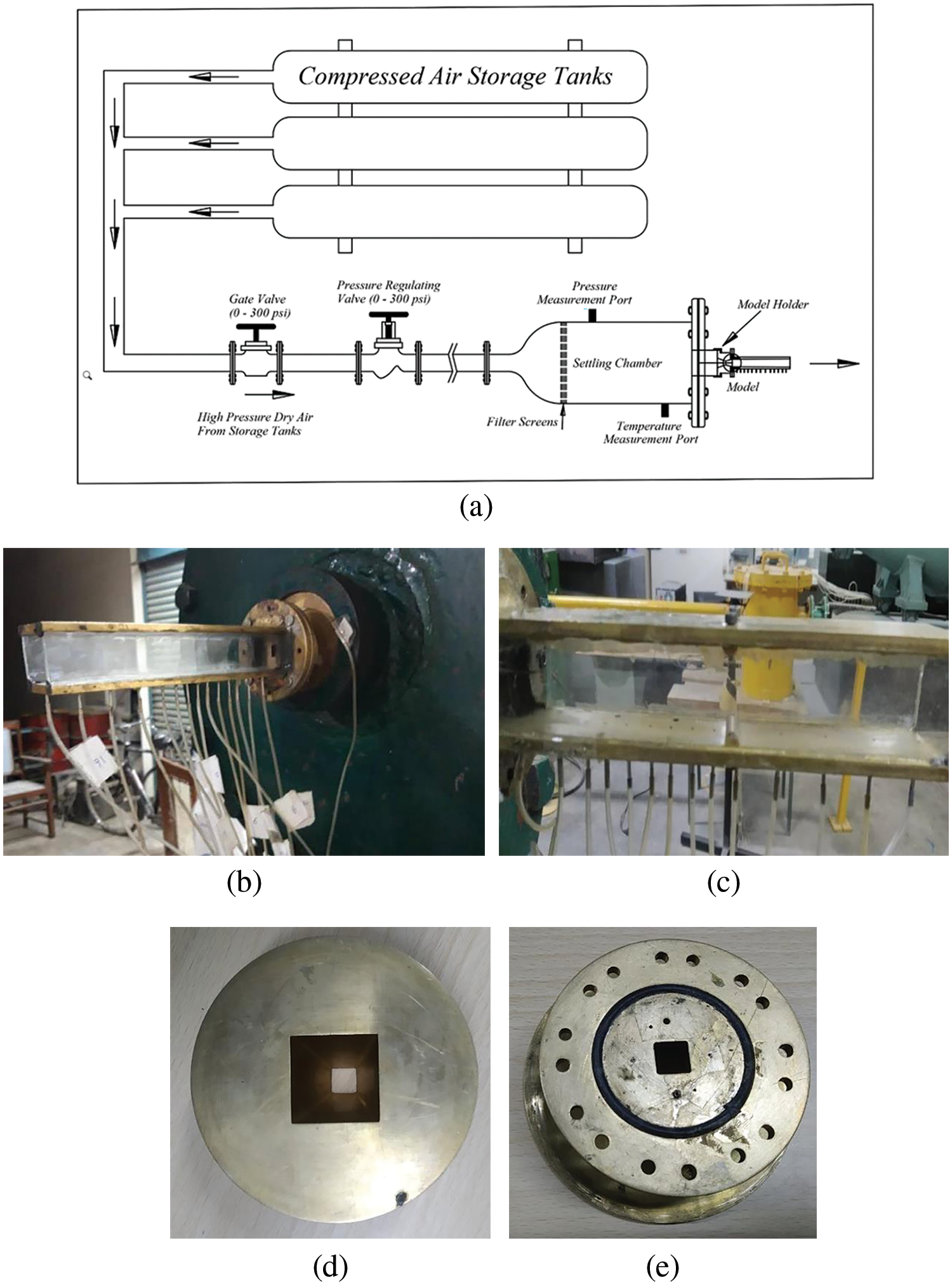
Figure 3: Experimental setup (a) Schematic diagram (b) Plain duct (c) Duct with semi-circular ribs (d) square nozzle and (e) Back side of nozzle
One of the variables in the current investigation is the nozzle pressure ratio (NPR), of which P0 is a primary component. NPR is obtained by dividing stagnation pressure in the settling chamber with ambient atmospheric pressure. The settling chamber pressure to atmospheric pressure ratio, or NPR (P0/Pa), is calculated. The nozzle created the expanded square duct, measuring 192 mm in length and 28 mm on each side, allowing the still air from the settling compartment to expand. In the current investigation, the convergent nozzle NPRs ranged from 1.5 to 7, and the converging-diverging nozzle NPRs from 2 to 10. The tests were conducted at sonic and four sonic Mach numbers: M = 1.5, 1.8, 2.2, and 2.5. In this paper, we discuss the results of sonic Mach numbers alone.
3.2.2 Validation of Experimental Results with CFD Simulations
For the Sonic Mach number, the nozzle flow is under the impact favorable pressure NPR greater than 2. Hence, as the NPR increases, the expansion level rises, increasing the base pressure in no control and making the control effective for the control case. For no-control cases, CFD and experimental results agree with each other. The same is seen for the control case. For no control case, the base pressure increases as the recirculation zone is more due to a high area ratio. Still, the expansion level is high, increasing the base pressure even at lower NPRs. When the rib is introduced in the flow field, it disturbs it by introducing weak secondary waves, increasing the base pressure more than in a control case. With the increase in the location of the rib, the base pressure rises as the rib is nearer to the reattachment point and coming well within the recirculation zone, having the power to show its effectiveness when compared to the same phenomenon at the lower rib location.
Fig. 4 presents base pressure results for the flow converging nozzle at various NPRs for 10 mm ribs diameter at a 1D location. The outcomes indicate good agreement between the investigational and CFD results. It is also seen that there is a downward trend in the base pressure even though the flow is under-expanded. However, due to the considerably large duct area, the under-expansion level cannot influence the flow field, and control is marginally effective as the location of the rib is very close to the base.
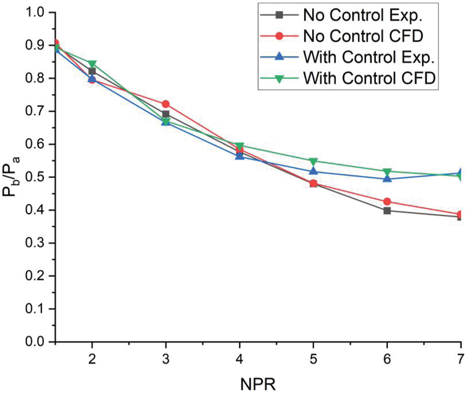
Figure 4: Validation of base pressure results of CFD and experimental at sonic Mach number for the semi-circular rib of 10 mm located at 1D for duct side of 28 mm
4.1 Analysis of 2 mm Semi-Circular Rib Diameter on the Flow Field
Before we explore the results concerning the variations in base pressure for different rib sizes, area ratios, nozzle pressure ratios, and locations, it is helpful first to grasp the flow dynamics occurring when the shear layer exits the nozzle and inserts a larger area. Upon leaving, the boundary layer divides, expands, and reattaches within the expanded duct if the Mach number is below one. Initially, a prominent vortex forms near the base, creating one or more vortices in the separated region, referred to as the central vortex. This vortex acts like a pump, moving fluids from the base to the primary jet along the boundary layer’s edge, causing a low-pressure area in the recirculation zone due to this pushing mechanism. It is critical to note that this pressing action is somewhat sporadic because the vortex formation occurs periodically. This leads to variations in base pressure that, although unpredictable, are found to be minor during testing. Hence, average base pressure values were utilized to evaluate the results. The cyclical nature of the vortex can cause the entire flow outline in the expanded area to oscillate, potentially becoming quite intense depending on specific geometric and inertial properties. The intensity of the core vortex at the base primarily rests on factors such as area ratio, Mach number, reattachment length, and the degree of expansion.
Fig. 5 illustrates the base pressure analysis corresponding to different NPR for a semi-circular rib of 2 mm diameter within a square duct of 15 mm side. At an NPR of 1.5, the flow conditions do not reach a critical state. Additionally, the square cross-section of the enlarged duct leads to the development of boundary layers on all sides, significantly complicating the flow field and likely contributing to a reduction in base pressure. However, starting from an NPR of 3, there is a noticeable increase in base pressure, which continues to rise unchecked, reaching a value of 0.8 at NPR 7. The primary physical mechanism driving this trend in cases without control involves the establishment of an expansion fan at the nozzle’s exit, where the flow encounters and relaxes past this expansion fan.
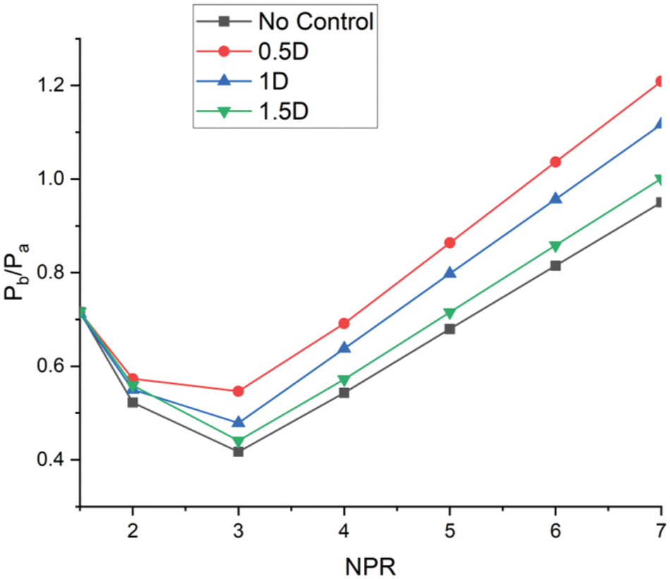
Figure 5: Base pressure vs. NPR plot for 0.5D, 1D, and 1.5D location for 2 mm semi-circular rib diameter
Wicks describes the cyclic flow process near the base as resulting from continuous flow injection near the base from the main flow, coupled with the ejection of flow from the base back into the main flow. The flow’s expansion further enhances this process through an expansion fan, which increases base pressure. In this scenario, the reattachment point occurs before 1D. When control is implemented at 0.5D, near the base region, the base pressure peaks compared to when passive control is applied at 1D or 1.5D locations. The primary reason for this is that with a duct side of 15 mm, which is relatively small, the placement of a semi-circular rib of 2 mm diameter at 0.5D introduces secondary vortices that interact with both the primary vortex (present even without passive control) and the main jet, significantly boosting the base pressure above atmospheric levels. Consequently, the 0.5D location increases the base pressure more than at the 1D and 1.5D locations due to the small diameter of the semi-circular rib. Therefore, this small-diameter semi-circular rib proves most effective when positioned near the base in this setup.
There is also a noticeable steady raise in the non-dimensional base pressure from an NPR of 3 onwards, even without passive control. However, the maximum increase is observed when passive control is applied at 0.5D. Therefore, if the goal is to enhance base pressure beyond atmospheric levels significantly, placing semi-circular rib controls at 0.5D is advisable. At the highest NPR of 7, the base pressure exceeds ambient pressure by 20%. In contrast, when the control mechanism is positioned at 1D, the base pressure is only 10% greater than the atmospheric pressure. These observations suggest that the reattachment point likely falls between 0.5D and 1D. Examining the effects at a rib location of 1.5D shows minimal control effectiveness, reinforcing that the reattachment point is before 1.5D and that the most effective rib placement for increasing base pressure above atmospheric levels is at 0.5D.
Fig. 6 shows the velocity contour for the control case when a semi-circular rib of 2 mm diameter is located at 0.5D. Due to the presence of the passive control flow in the enlarged duct getting accelerated, as seen in Fig. 6, there is a reduction in the relief for the flow which was available without control case. For this case, the level of under-expansion is 2. The flow accelerates in a significant part of the duct (i.e., nearly sixty percent of the duct segment) due to the under-expanded nozzle. While the flow is exiting, the nozzle is under-expanded; hence, at the exit of the nozzle, an expansion fan will be formed, resulting in the acceleration of the flow and leading to a shorter reattachment length. Fig. 7 shows the pressure contour at NPR 7 when passive control of a 2 mm radius is placed at 0.5D. At NPR 7, the level of under-expansion has further increased (i.e., Pe/Pa = 3.5). Under these conditions, when the flow is exhausted, an enlarged duct will continue to expand through the entire length of the duct, as seen in Fig. 6.
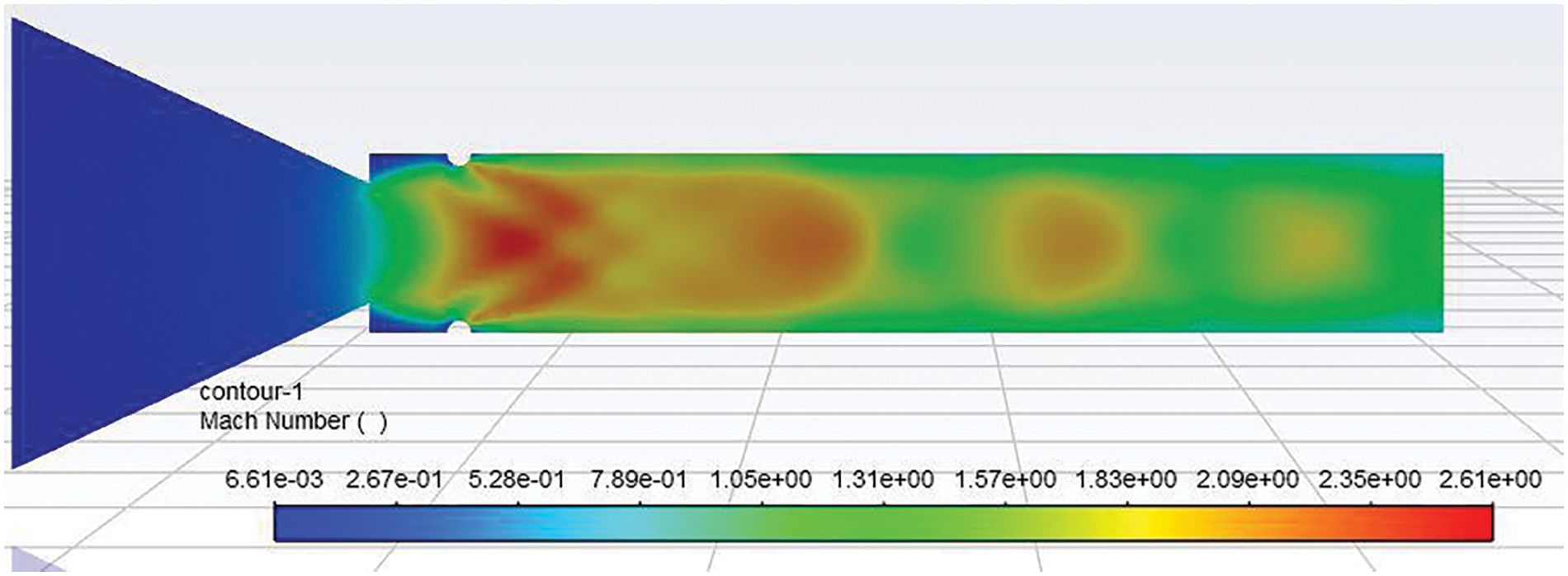
Figure 6: Mach number contour of 2 mm semi-circular rib placed at 0.5D location at NPR 4
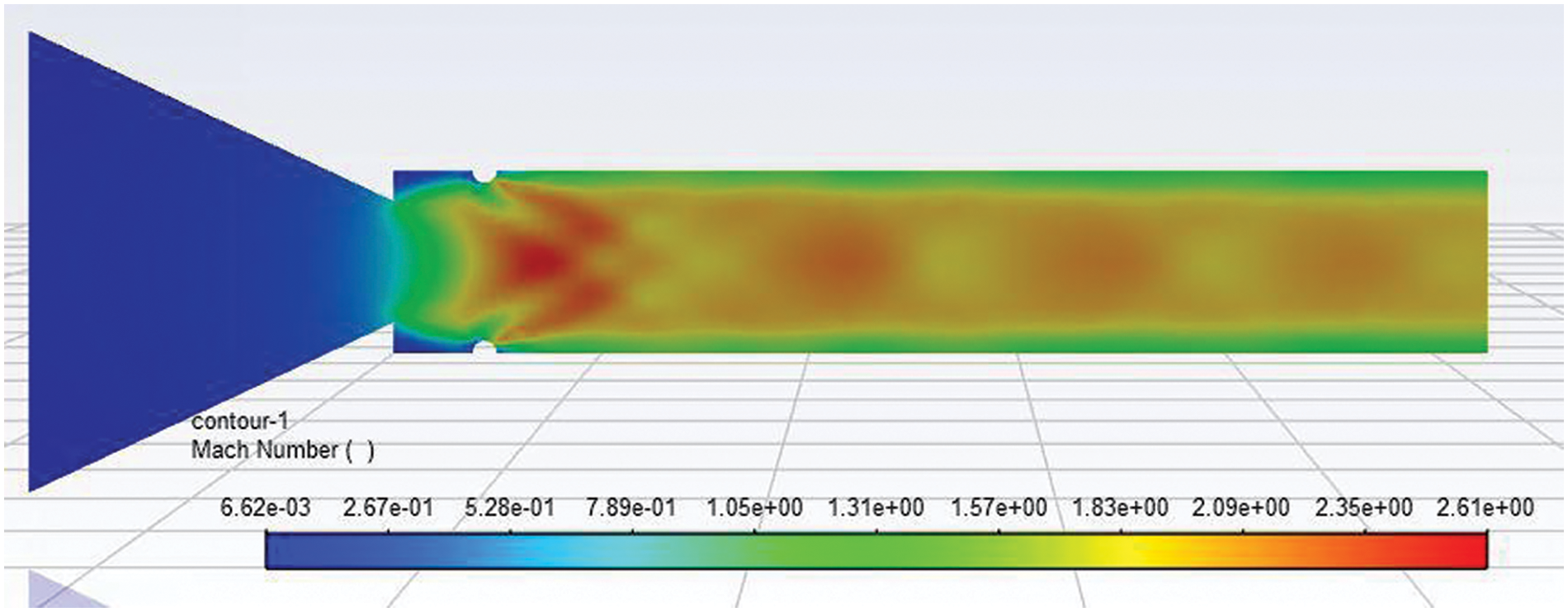
Figure 7: Mach number contour of 2 mm semi-circular rib placed at 0.5D location at NPR 7
Figs. 8 and 9 show the Mach number contour when a 2 mm semi-circular rib is placed at a 1D location at NPRs 5 and 7. Figs. 8 and 9 show that a strong Mach disc is located before the rib location. These results reiterated that the stream reattachment by the duct wall is well ahead of the 1D position, resulting in a strong shock wave formation, and the two small shock waves downstream are visible. Since the significant expansion of the flow took place before the 1D location and later towards the exit of the duct, Mach waves were seen.
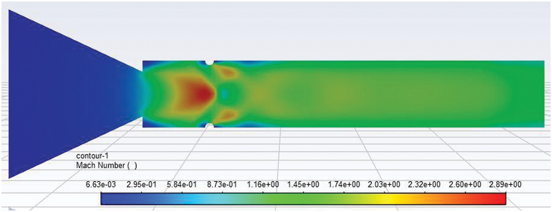
Figure 8: Mach number contour of 2 mm semi-circular rib placed at a 1D location at NPR 5

Figure 9: Mach number contour of 2 mm semi-circular rib placed at a 1D location at NPR 7
Fig. 10 above shows the base pressure deviation NPR for positions 2D, 3D, and 4D for a semi-circular rib of 2 mm. From the results of Fig. 4, it was demonstrated that this rib is most effective when placed near the base as it is within the reattachment point, forming several waves owing to the presence of the semi-circular rib due to the gradual change in the slope it will not create a strong shock wave rather many Mach waves are formed and that results in an isentropic flow. Hence, from the above Fig. 10, it is realized that the base pressure increase is the maximum for 2D as compared to 3D and 4D locations as the 2D rib location is very close to the reattachment point and also from the recirculation zone/base when compared to 3D and 4D locations. Hence, for the given flow parameters, the most effective location for the ribs seems to be the 2D location. For the remaining locations of the ribs at 3D and 4D, there is a marginal growth in the base pressure, and the change of rib location from 3D to 4D does not lead to any appreciable change in the base pressure. Hence, we may state that the optimum rib location for a 2 mm rib diameter is 0.5D if the maximum enhancement in the base pressure is the objective.
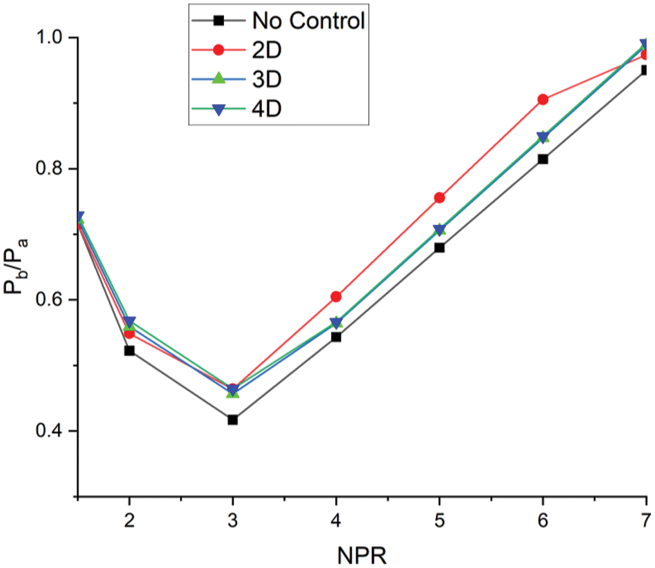
Figure 10: Base pressure vs. NPR plot for 2D, 3D, and 4D location for 2 mm semi-circular rib diameter
4.2 Analysis of 4 mm Semi-Circular Rib Diameter on the Flow Field
From Fig. 11, the semi-circular rib is placed at 0.5D, 1D, and 1.5D locations, but the rib diameter is increased by 2 mm. The increased diameter of the rib of 4 mm generates stronger secondary vortices, which interact well with the main flow and primary vortex when placed at 0.5D and 1.5D locations. The reason for the semi-circular rib of 4 mm is to become effective at the 1.5D location is due to its location beyond the reattachment point. It is well known that after the reattachment points, the boundary layer will grow again, the flow downstream will experience a large area, and the flow will interact with secondary vortices formed by the ribs. Also, the decreasing trend in the base pressure is getting arrested, and the increasing trend starts at the NPR 2 when controls are employed. However, in the previous case where the rib diameter was 2 mm. this trend was seen at NPR 3. This may be due to the augmented rib diameter, but the relief available to the flow is decreased due to the increased diameter of the rib. The maximum rise in the base pressure is observed for control positions 0.5D and 1.5D, and the rib location of 1D, which showed results, cannot influence the flow. When the duct side is as low as 15 mm, the larger diameter of the rib is found most effective when placed farther from the base as it gives some space for the interaction of an increased number of secondary vortices due to the larger diameter of the rib to interact with primary vortex and the main flow.
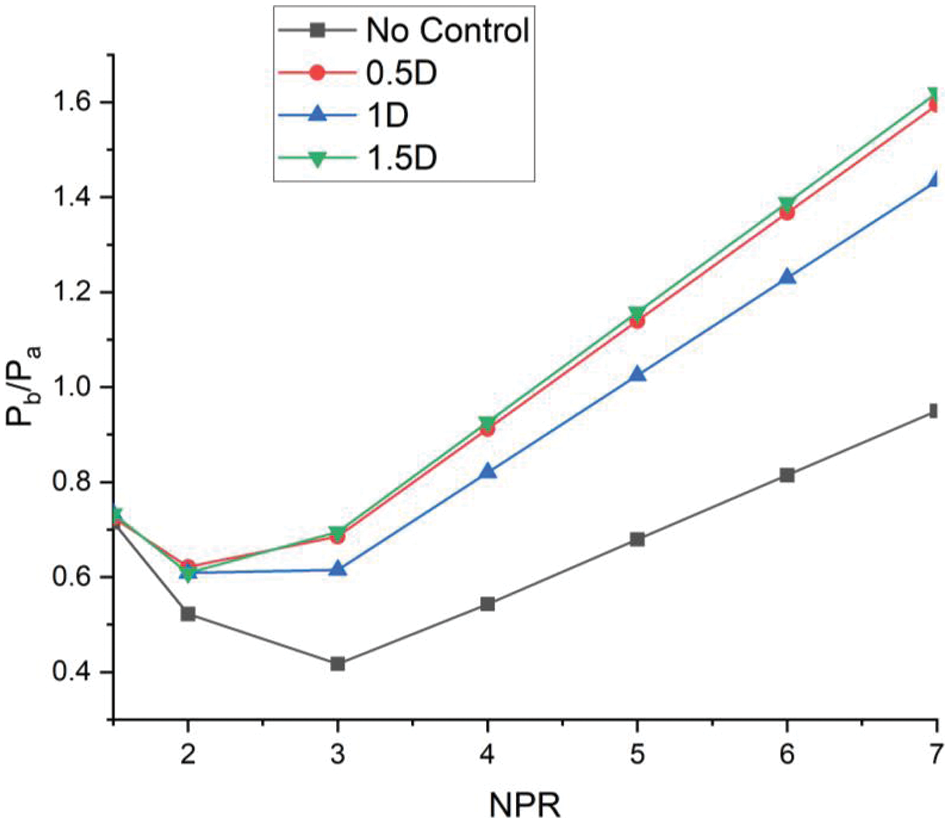
Figure 11: Base pressure vs. NPR plot for 0.5D, 1D, and 1.5D location for 4 mm semi-circular rib diameter
Figs. 12 and 13 show that as there is an increment in the rib diameter, it can show its effect on the flow field. The expansion fan formation is more significant; hence, the turbulent interactions between the fan and oblique shock waves are much more complex and chaotic—Mach number contour of 4 mm diameter semi-circular rib placed at a 1D location at NPR 7. When the same rib size, i.e., 4 mm, is placed at a 1D position, it can be observed that due to the change in the position of the rib, the flow cannot be influenced to that extent. Fig. 11 shows the Mach number contour for a 4 mm diameter rib at 0.5D when nozzle pressure ratio (NPR) = 4, and we can see that an increase in the radius of the rib flow is facing more blockage, which increases the base pressure. Further, the shock waves interact with up to thirty percent of the duct downstream. Later, the shock waves are weakened, and they disappear. Fig. 12 shows the Mach number contour for a 4 mm diameter rib at 0.5D when nozzle pressure ratio (NPR) = 7. The results are similar as all the parameters are the same, except the NPR has increased from 4 to 7. The NPR level of under-expansion has increased considerably to 3.5 (i.e., Pe/Pa = 3.5). This increase in under-expansion has resulted in a longer trail of the shock waves downstream, which was limited to sixty percent of the duct length in the previous case.
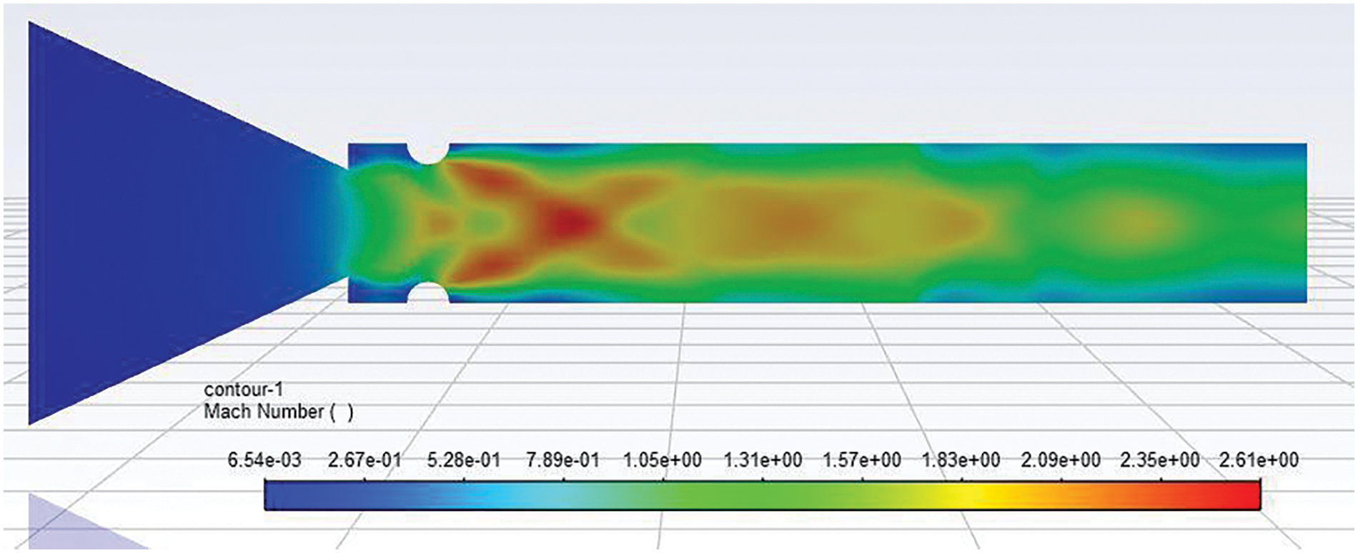
Figure 12: Mach number contour of 4 mm semi-circular rib placed at 0.5D location at NPR 4
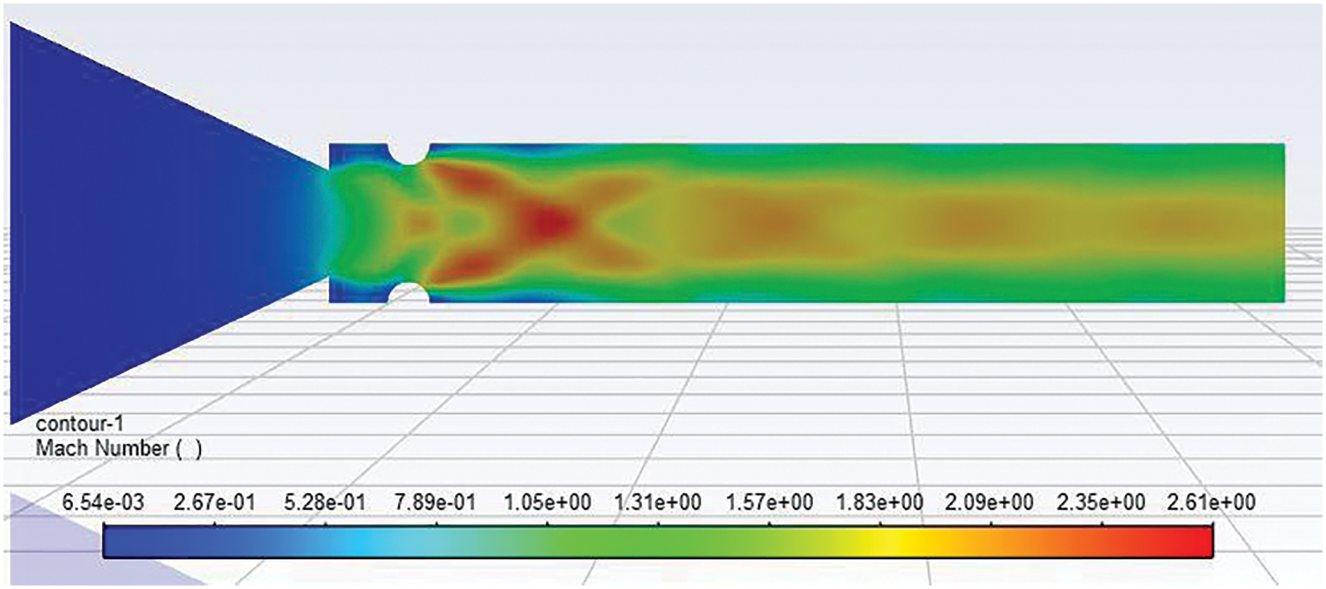
Figure 13: Mach number contour of 4 mm semi-circular rib placed at 0.5D location NPR 7
Fig. 14 shows the Mach number contour for a 4 mm diameter semi-circular rib at 1D and NPR 4. Due to the change in the passive control to 1D, there is a considerable change in the flow field. There is a strong shock wave before and after the rib. Further downstream, the field contains at least one Mach disc, and later, waves disappear due to the regaining of the wall pressure, which happens to be almost equal to the atmospheric pressure. Fig. 15 shows the Mach number contour for a 4 mm diameter semi-circular rib at 1D, and NPR 7, and the results are similar as all the parameters are the same, except the NPR has increased from 4 to 7. The NPR level of under-expansion has increased considerably to 3.5 (i.e., Pe/Pa = 3.5). This rise in the level of under-expansion of the flow will increase the number of the waves as it must expand till the wall pressure is equal to the ambient pressure and will have a longer trail of the shock waves downstream, which was limited to sixty percent of the duct length in the previous case.
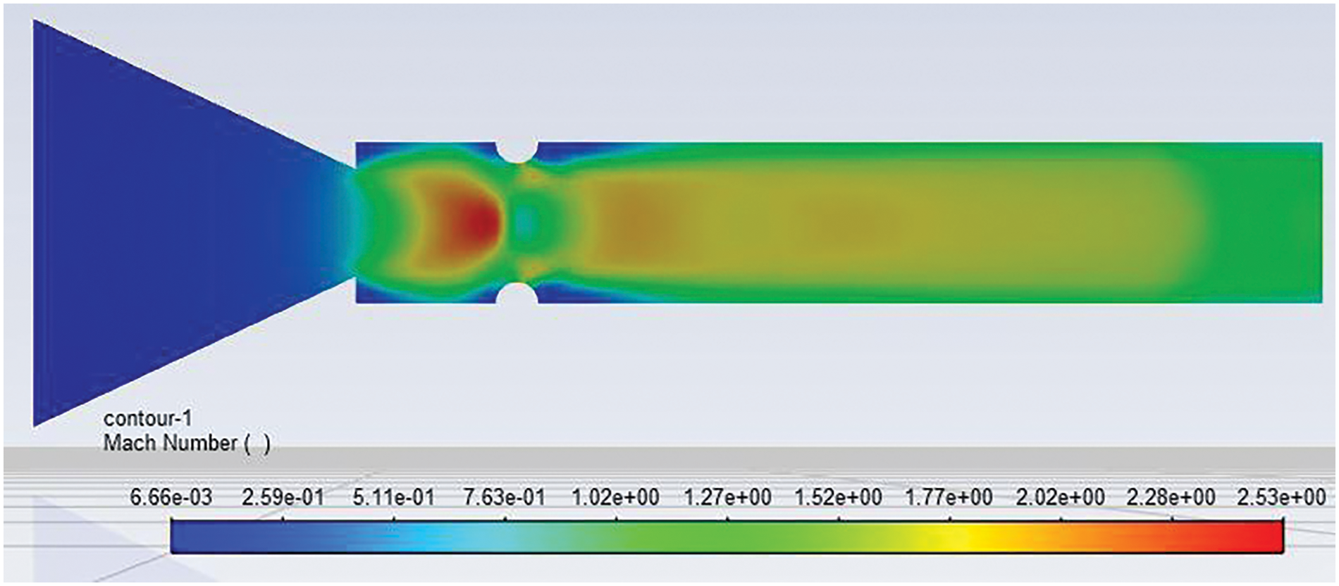
Figure 14: Mach number contour of 4 mm semi-circular rib placed at 1D location at NPR 4
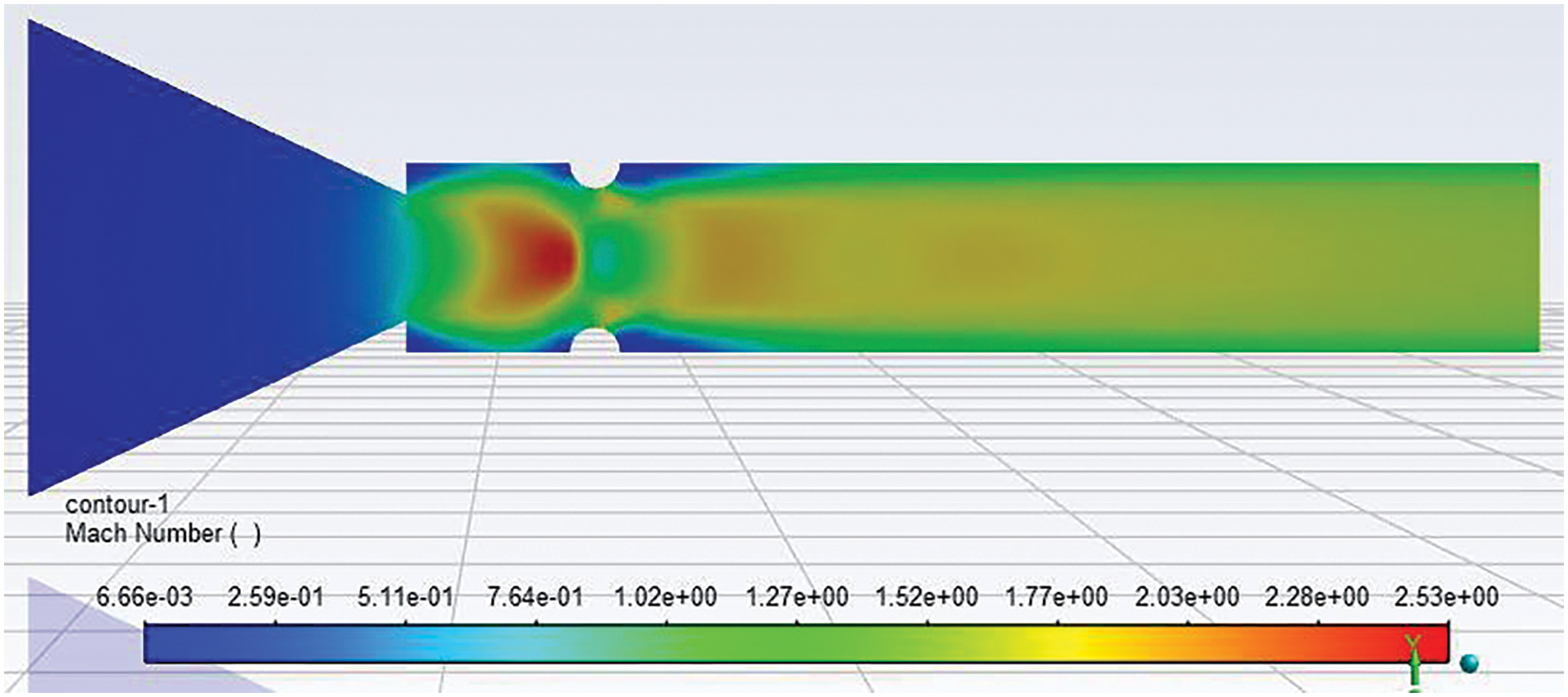
Figure 15: Mach number contour of 4 mm semi-circular rib placed at a 1D location at NPR 7
Fig. 16 shows the base pressure changes with NPR for three rib positions, namely 2D, 3D, and 4D, when the rib radius is 4 mm. Here, the maximum rise in the base pressure is found for the 4D location as enough space is given to the secondary vortices, primary vortex, and main flow to interact with each other. Then, the passive controls in the 3D location and 2D location underperformed. The rise in the base pressure when the semi-circular rib is located at a 4D location is eighty percent more than atmospheric pressure; at 3D, it is 50% more, and at 2D, it is 40% more than atmospheric pressure. Without control, it has nearly reached atmospheric pressure. Results indicate that when NPR 1.5, the base pressure values are as the nozzle has not choked, and this pattern continued till the nozzle was under-expanded. Without the control mechanism, this decreasing base pressure trend remains until NPR 3. Later, when NPR is greater than 3, there is a gradual rise in the base pressure. When semi-circular ribs as a control mechanism are placed at three locations, as discussed above, the 4D location seems to be the best position if the growth in the base pressure is the objective.
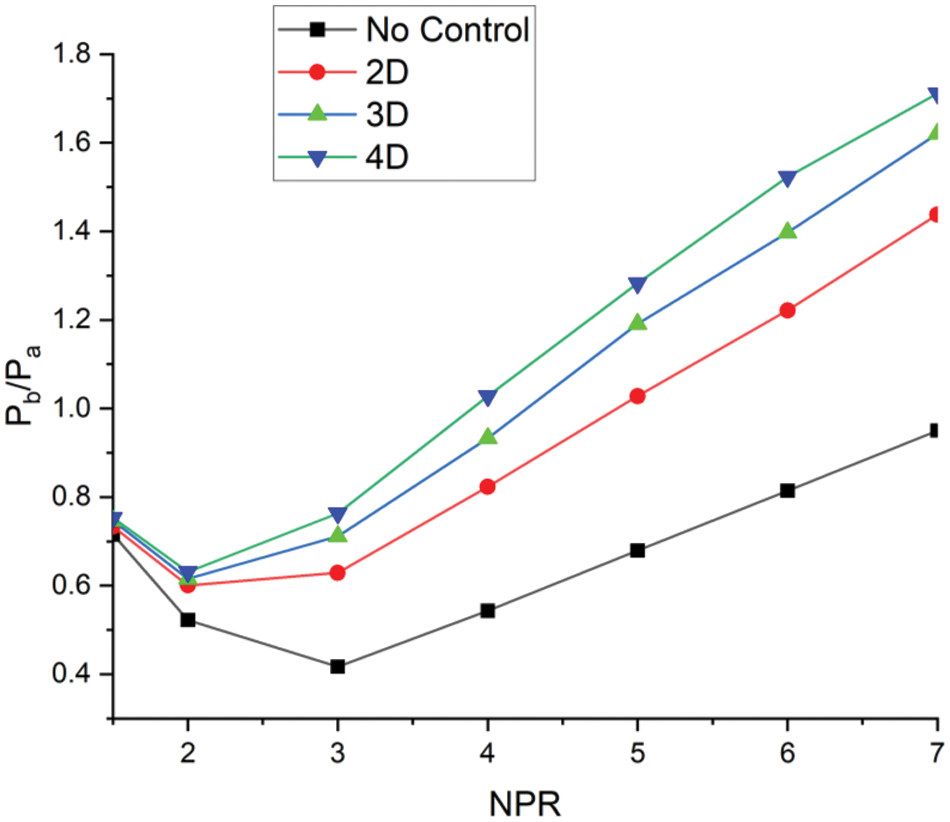
Figure 16: Base pressure vs. NPR plot for 2D, 3D, and 4D location for 4 mm semi-circular rib diameter
4.3 Analysis of 6 mm Semi-Circular Rib Diameter on the Flow Field
Fig. 17 shows base pressure results when the semi-circular rib is located at 0.5D, 1D, and 1.5D locations, but the rib diameter is 6 mm. The increased diameter of the rib of 4 mm generates stronger secondary vortices, which interact well with the main flow and primary vortex when placed at 0.5D and 1.5D locations. The reason for the semi-circular rib of 4 mm is to become effective at the 1.5D location is due to its location beyond the reattachment point. It is well known that after the reattachment point, the boundary layer will grow, and the stream will interact with secondary vortices formed by the ribs. Also, the decreasing trend in the base pressure is getting arrested, and the increasing trend starts at the NPR 2. However, in the previous case where the rib diameter was 2 mm. this trend was seen at NPR 3. This may be due to the increased rib diameter, but the relief available to the flow is decreased due to the increased rib diameter. It is also seen that due to the increase in the radius of the semi-circular ribs, there is a change in the reattachment point due to the blockage created by the passive control. This may be one of the reasons for control becoming more effective at rib locations of 1D and 1.5D. When the duct side is as low as 15 mm, the larger diameter of the rib is found most effective when placed farther from the base as it gives some space for the interaction of an increased number of secondary vortices due to the larger diameter of the rib to interact with primary vortex and the main flow. Hence, if the user requires to increase the base pressure to twice or more than twice the ambient pressure, then the best control locations are 0.5D and 1D/1.5D.

Figure 17: Base pressure vs. NPR for 0.5D, 1D, and 1.5D rib locations for 6 mm rib
Fig. 18 shows the velocity contour for a 6 mm semi-circular rib diameter at 0.5D for NPR 4. At NPR 4, the exiting flow stream is under-expanded, and the level of under-expansion is 2 (i.e., Pe/Pa = 2.0). Initially, flow is decelerated; however, beyond the rib location, there is a significant rise in the flow speed. The first shock is vital as the stream is under-expanded to its highest level. Later downstream, there is a decrease in the under-expansion level; expansion waves weaken and ultimately disappear once the pressure in the duct approaches the ambient pressure.
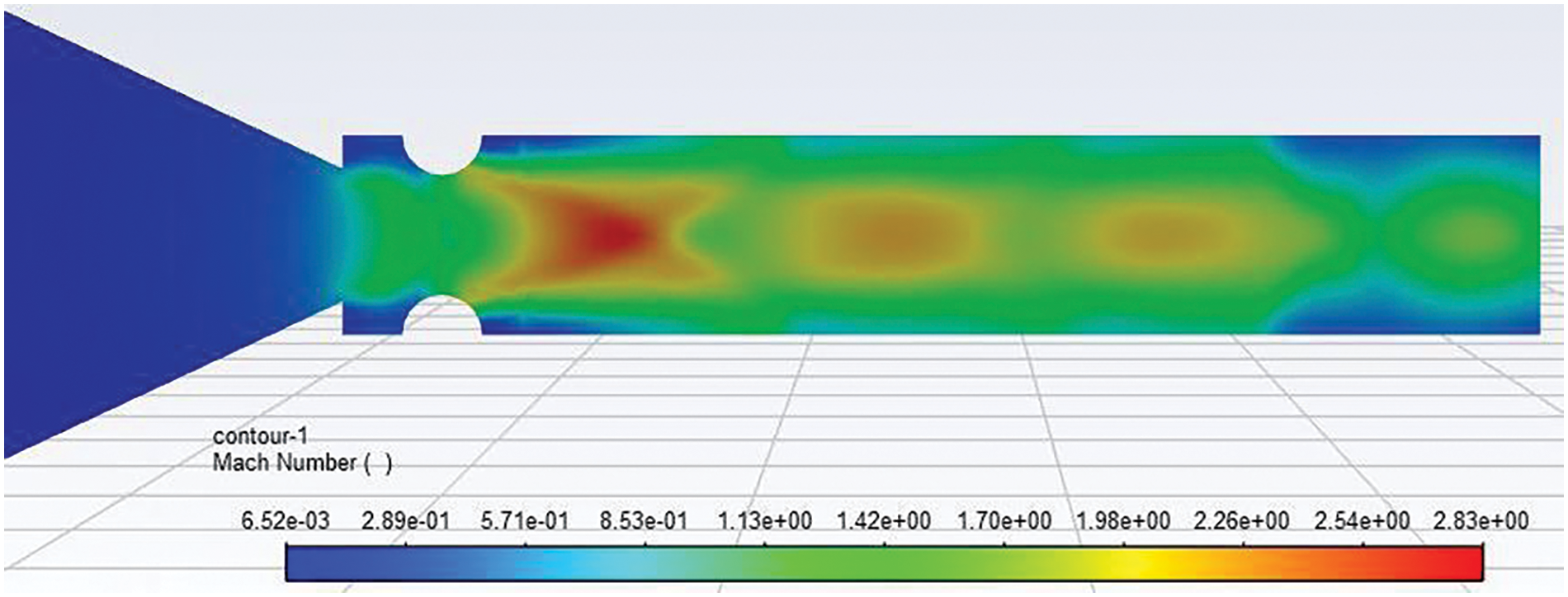
Figure 18: Velocity contour of 6 mm semi-circular rib placed at a 0.5D location at NPR 4
Fig. 19 shows the velocity contour for a 6 mm diameter semi-circular rib at 0.5D location at NPR 7. The only difference between Figs. 18 and 19 is that the level of under-expansion has increased from 2 to 3.5. This increased level of under-expansion will require a longer duct length to achieve ambient conditions, as reflected in Fig. 5c.
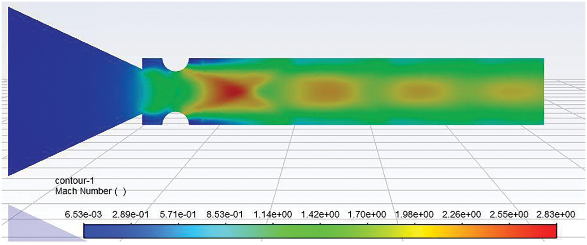
Figure 19: Velocity contour of 6 mm semi-circular rib placed at a 0.5D location at NPR 7
Mach number contour for 6 mm diameter ribs at ribs locations of 1D when NPR 4 is depicted in Fig. 20. Due to the change in the rib location from 0.5D to 1D, other parameters remain the same as in Fig. 17. Due to the change in the location of the ribs, the flow will get enough relief to expand. Later downstream, near the rib location, the flow will be compressed, forming an intense wave. We can see two Mach discs before the flow decelerates considerably. After the third Mach disc, the flow has decelerated considerably.
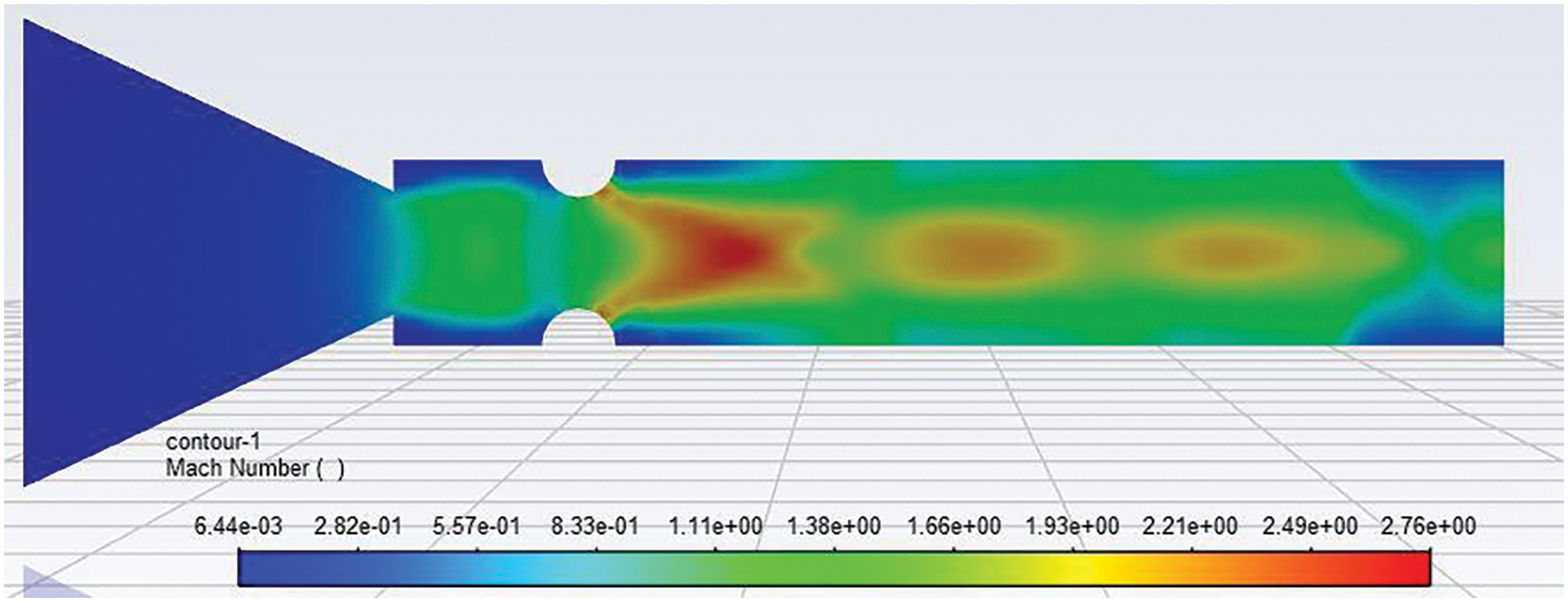
Figure 20: Mach number contour of 6 mm semi-circular rib placed at a 1D location at NPR 4
With the level of under-expansion of 3.5, the Mach number contour for NPR 7, rib diameter 6 mm, and rib location of 1D is presented in Fig. 21. From the above Mach number contours for the enhanced level of under-expansion of 3.5, the flow field is influenced by the rib diameter to a more considerable extent. As expected, the wave formation will remain till the duct’s flow has achieved ambient conditions. When the NPR was four, the waves disappeared from the duct. However, due to the increased NPR 7, more space is needed to expand, and that did not happen within this duct length of L = 6D.
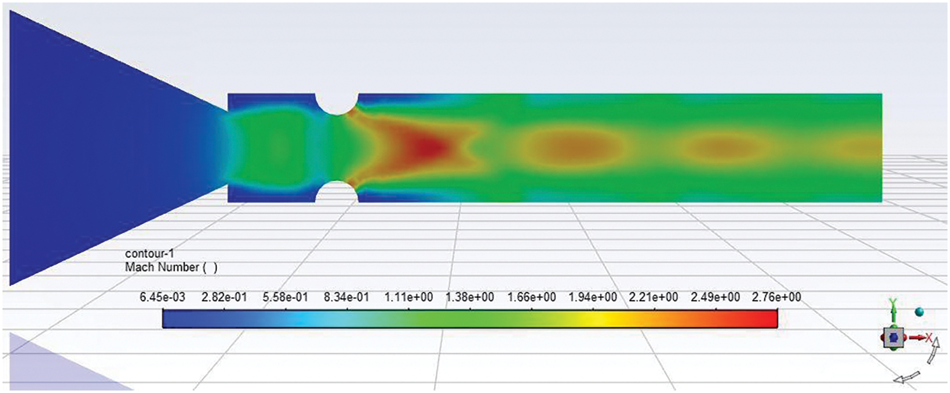
Figure 21: Mach number contour of 6 mm semi-circular rib placed at a 1D position at NPR 7
Base pressure results for three rib locations, namely 2D, 3D, and 4D for NPRs in the range from 1.5 to 7, are shown in Fig. 22. Results indicate that base pressure results in the absence of control remain the same due to a progressive increase in the diameter of the ribs; when the ribs are placed at a 4D location, control results in an extreme rise in the base pressure, which is 2.9 times the ambient pressure. For the other two locations, namely 3D and 2D, the base pressure values are 2.7 and 2.4 times the ambient pressure. The 4D location of the ribs continues to develop in the most considerable base pressure. However, the base pressure values are marginally different for this case, unlike in previous instances when the rib’s diameters were 2 mm and 4 mm. At lower rib diameter, the 4D location was the most effective; it could block the flow, and there were excellent interactions of the flow within the duct that resulted in higher base pressure values. Nevertheless, once the rib diameter is 6 mm, the influence of the 4D location is reduced, and under these circumstances, the other two locations can also decrease the base suction.
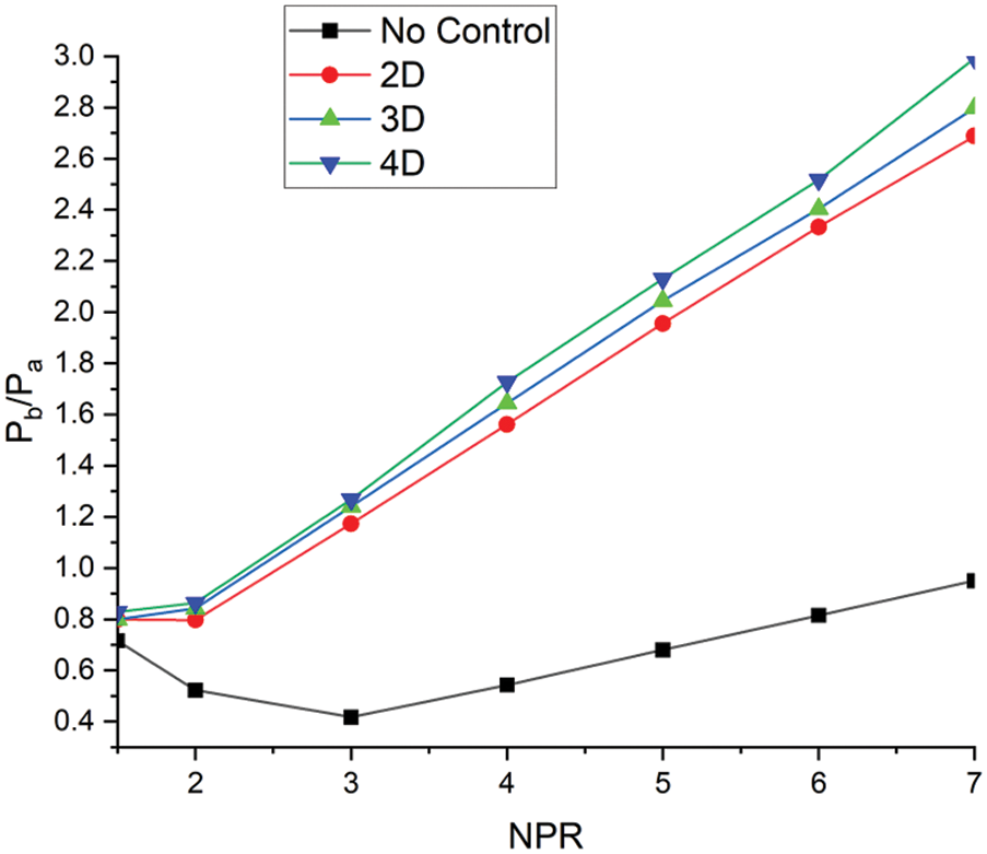
Figure 22: Base pressure vs. NPR plot for 2D, 3D, and 4D location for 6 mm semi-circular rib diameter
Fig. 23a, b show the pressure and velocity contour for NPR 4. From the contours, it can be confirmed that at NPR 4, the under-expansion level is two linked to Fig. 24a, b, where the NPR is seven, and the level of under-expansion is 3.5, which is relatively high. Hence, the influence of rib in the control case is more effective at NPR 7 than at NPR 4.
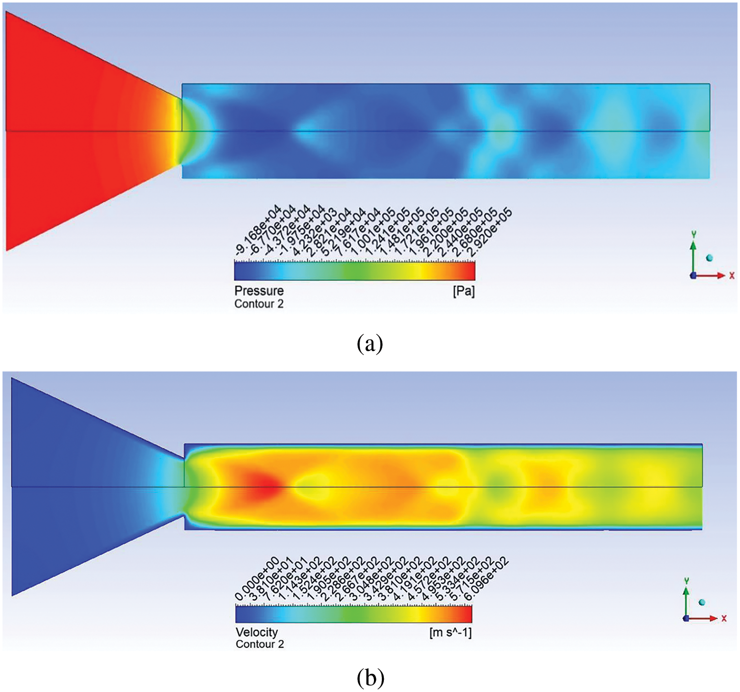
Figure 23: Contour for no control case for NPR 4 (a) Pressure (b) Velocity
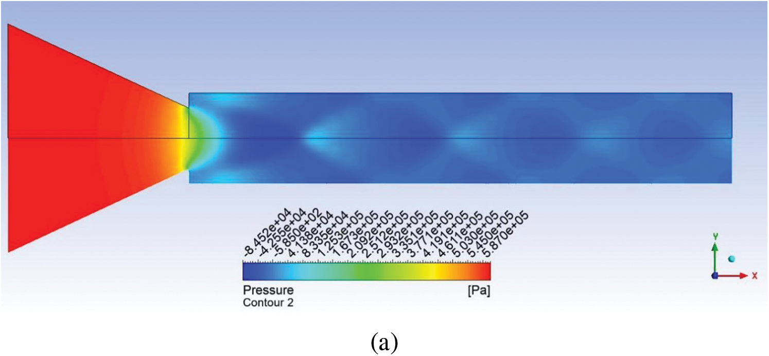
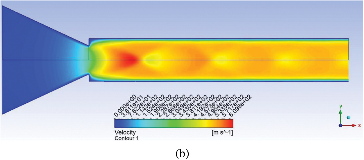
Figure 24: Contour for no control case for NPR 7 (a) Pressure (b) Velocity
Established on the above discussion, we resolve as follows:
1. From the analysis of 2 mm of rib diameter, it can be concluded that it is most effective when placed at a 0.5D location. As the location of the rib changes, its effect decreases compared to that of the rib located near the base.
2. For the 4 mm rib diameter, it is observed that when the rib is placed at a 1.5D and 4D location, the base pressure increases by 60% and 70% more than the ambient atmospheric pressure. This is effective due to the rise in the rib diameter’s size, which results in the blockage of the flow and, finally, an increase in the base pressure and a decrease in the base drag, which is substantial at critical Mach numbers.
3. When increasing rib diameter to 6 mm, it shows its most effective effect at 1.5D and 4D locations, with a 260% and 300% increase in base pressure, respectively. Here, the height of the ribs becomes the defining factor that dictates the base pressure values and, ultimately, the base drag.
4. From the Mach number contours, it can be observed that the flow field changes with the change in the rib size and location. Due to the increase in the under-expansion levels from 2 to 3.5, the entire duct is full of waves as it takes a longer duct length to attain duct pressure equal to the ambient pressure.
5. The pressure and velocity contours without control case show the effect of the level of underexpansion on the flow field. For the highest level of underexpansion, the waves occupy the entire enlarged duct; for the level of underexpansion of 3.5, it takes maximum duct length to attain the ambient atmospheric pressure.
The different types of passive control with variable shapes and sizes can be considered for flow control. Corrugated ribs can also be used to regulate the base pressure. It is expected that the corrugated ribs may give some interesting results as it has multiple sharp corners, and these numerous vortices, while interacting with the primary vortex, will result in a considerable rise in the base pressure and, hence, a decrease in the base drag. These multiple sharp corners will generate streamwise secondary vortices, resulting in excessive interaction between primary and secondary vortices and maximum enhancement in the base pressure. We may also try trapezoidal ribs to control the base pressure. Corrugation can also be tried on the side facing the inflow and on the other side without corrugation; later, both sides can be corrugated. Ribs as passive control have disadvantages in the form of added weight to the aerospace vehicle, where the weight plays a crucial role. The study can be in active control, and we may draw the energy from the primary chamber.
Along with passive control, active control can also be used to make it a hybrid control. Using hybrid control may give better results, and we can find optimum locations for passive and active controls. The flow conditions can vary from sonic to supersonic conditions.
Acknowledgement: The authors would like to acknowledge the Indian Institute of Technology, Kanpur, India, for allowing us to use their high-speed aerodynamics laboratory research facility.
Funding Statement: This research is supported by the Structures and Materials (S&M) Research Lab of Prince Sultan University, and the authors acknowledge the support of Prince Sultan University in paying the article processing charges (APC) for this publication.
Author Contributions: The authors confirm their contribution to the paper as follows: study conception and design: Ambareen Khan, Sher Afghan Khan; data collection: Ambareen Khan; analysis and interpretation of results: Sher Afghan Khan, Mohammed Nishat Akhtar, Abdul Aabid, Muneer Baig; draft manuscript preparation: Sher Afghan, Abdul Aabid. All authors reviewed the results and approved the final version of the manuscript.
Availability of Data and Materials: Data is available to the corresponding author upon request.
Conflicts of Interest: The authors declare that they have no conflicts of interest to report regarding the present study.
References
1. Afzal A, Aabid A, Khan A, Khan SA, Nath T, Kumar R. Response surface analysis, clustering, and random Forest regression of pressure in suddenly expanded high-speed aerodynamic flows. Aerosp Sci Technol. 2020;1(1):106318. doi:10.1016/j.ast.2020.106318. [Google Scholar] [CrossRef]
2. Khan A, Rajendran P, Sidhu JSS. Passive control of base pressure: a review. Appl Sci. 2021;11(3):1–22. doi:10.3390/app11031334. [Google Scholar] [CrossRef]
3. Khan SA, Rathakrishnan E. Active control of suddenly expanded flows from overexpanded nozzles. Int J Turbo Jet Engines. 2002;19(1–2):119–26. doi:10.1515/TJJ.2002.19.1-2.119. [Google Scholar] [CrossRef]
4. Rathakrishnan E. Effect of ribs on suddenly expanded flows. AIAA J. 2001;39(7):1402–4. [Google Scholar]
5. Vijayaraja K, Senthilkumar C, Elangovan S, Rathakrishnan E. Base pressure control with annular ribs. Int J Turbo Jet Engines. 2014;31(2):111–8. doi:10.1515/tjj-2013-0037. [Google Scholar] [CrossRef]
6. Khan SA, Abdul Aabid CAS. Influence of micro jets on the flow development in the enlarged duct at supersonic mach number. Int J Mech Mechatron Eng. 2019;19(1):70–82. [Google Scholar]
7. Asadullah M, Khan SA, Asrar W, Sulaeman E. Low-cost base drag reduction technique. Int J Mech Engi Robot Res. 2018;7;428–32. doi:10.18178/ijmerr.7.4.428-432. [Google Scholar]
8. Pathan KA, Dabeer PS, Khan SA. Investigation of base pressure variations in internal and external suddenly expanded flows using CFD analysis. CFD Lett. 2019;11(4):32–40. [Google Scholar]
9. Akhtar MN, Bakar EA, Aabid A, Khan SA. Effects of micro jets on the flow field of the duct with sudden expansion. Int J Innov Technol Explor Eng. 2019;8(9S2):636–40. doi:10.35940/ijitee.I1129.0789S219. [Google Scholar] [CrossRef]
10. Khan SA, Aabid A, Chaudhary ZI. Influence of control mechanism on the flow field of duct at Mach 1.2 for area ratio 2.56. Int J Innov Technol Explor Eng. 2019;8(6S4):1135–8. doi:10.35940/ijitee.F1236.0486S419. [Google Scholar] [CrossRef]
11. Aabid A, Afifi A, Ahmed Ghasi Mehaboob Ali F, Nishat Akhtar M, Afghan Khan S. CFD analysis of splitter plate on bluff body. CFD Lett. 2019;11:25–38. [Google Scholar]
12. Akhtar MN, Bakar EA, Aabid A, Khan SA. Numerical simulations of a CD nozzle and the influence of the duct length. Int J Innov Technol Explor Eng. 2019;8(9S2):622–30. doi:10.35940/ijitee.I1127.0789S219. [Google Scholar] [CrossRef]
13. Jodai Y, Takahashi Y, Ichimiya M, Osaka H. The effects of splitter plates on turbulent boundary layer on a long flat plate near the trailing edge. J Fluids Eng Trans ASME. 2008;130(5):0511031–7. doi:10.1115/1.2911683. [Google Scholar] [CrossRef]
14. Reedy TM, Elliott GS, Dutton JC, Lee Y. Passive control of high-speed separated flows using splitter plates. AIAA J. 2012;50(7):1586–95. doi:10.2514/1.J051566. [Google Scholar] [CrossRef]
15. Siddiqui NA, Chaab MA. A simple passive device for the drag reduction of an ahmed body. J Appl Fluid Mech. 2021;14(1):147–64. doi:10.47176/jafm.14.01.31791. [Google Scholar] [CrossRef]
16. Mariotti A, Buresti G, Salvetti MV. Separation delay through contoured transverse grooves on a 2D boat-tailed bluff body: effects on drag reduction and wake flow features. Eur J Mech B/Fluids. 2019;74(11):351–62. doi:10.1016/j.euromechflu.2018.09.009. [Google Scholar] [CrossRef]
17. Capone A, Romano GP. Investigation on the effect of horizontal and vertical deflectors on the near-wake of a square-back car model. J Wind Eng Ind Aerodyn. 2019;185:57–64. doi:10.1016/j.jweia.2018.12.011. [Google Scholar] [CrossRef]
18. Pavia G, Passmore M, Varney M. Low-frequency wake dynamics for a square-back vehicle with side trailing edge tapers. J Wind Eng Ind Aerodyn. 2019;184:417–35. doi:10.1016/j.jweia.2018.12.009. [Google Scholar] [CrossRef]
19. Choi H, Jeon WP, Kim J. Control of flow over a bluff body. Annu Rev Fluid Mech. 2008;40(1):113–39. doi:10.1146/annurev.fluid.39.050905.110149. [Google Scholar] [CrossRef]
20. Abedin MZ, Mukut ANMMI. Review on aerodynamic drag reduction of vehicles. Int J Eng Mater Manuf. 2019;4:1–14. [Google Scholar]
21. Mehta RC. Drag reduction for payload fairing of the satellite launch vehicle with aerospike in transonic and low supersonic speeds. Adv Aircr Spacecr Sci. 2020;7(4):371–85. [Google Scholar]
22. Lo KH, Zare-Behtash H, Kontis K. Control of flow separation on a contour bump by jets in a Mach 1.9 freestream: an experimental study. Acta Astronaut. 2016;126(5):229–42. doi:10.1016/j.actaastro.2016.04.033. [Google Scholar] [CrossRef]
23. Lo KH, Kontis K. Flow characteristics of various three-dimensional rounded contour bumps in a Mach 1.3 freestream. Exp Therm Fluid Sci. 2017;80(12):228–43. doi:10.1016/j.expthermflusci.2016.08.027. [Google Scholar] [CrossRef]
24. Khan A, Rajendran P, Sidhu JSS, Thanigaiarasu S, Raja V, Al-Mdallal Q. Convolutional neural network modeling and response surface analysis of compressible flow at sonic and supersonic Mach numbers. Alex Eng J. 2023;65(5):997–1029. doi:10.1016/j.aej.2022.10.006. [Google Scholar] [CrossRef]
25. Khan A, Rajendran P, Sidhu JSS, Sharifpur M. Experimental investigation of suddenly expanded flow at sonic and supersonic Mach numbers using semi-circular ribs: a comparative study between experimental, single layer, deep neural network (SLNN and DNN) models. Eur Phys J Plus. 2023;138(4):314. doi:10.1140/epjp/s13360-023-03853-1. [Google Scholar] [CrossRef]
26. Nurhanis T, Khan A, Akhtar MN, Khan SA. Control of base pressure at supersonic mach number in a suddenly expanded flow. J Adv Res Fluid Mech Therm Sci. 2023;109(1):210–25. doi:10.37934/arfmts.109.1.210225. [Google Scholar] [CrossRef]
27. Khan A, Mazlan NM, Sulaeman E. Effect of ribs as passive control on base pressure at sonic mach numbers. CFD Lett. 2022;14(1):140–51. doi:10.37934/cfdl.14.1.140151. [Google Scholar] [CrossRef]
28. Rathakrishnan E. Base heating and stage separation of launch vehicles. Aeronaut J. 2023;127(1315):1–13. doi:10.1017/aer.2023.13. [Google Scholar] [CrossRef]
29. Li G, Sun H, Tang Q, Zhen H, Wang H, Liu H, et al. Fundamental insights on turbulence characterization, vortex motion and ignition mechanism of sub/supersonic turbulent jet flames. Appl Therm Eng. 2024 Jul;248:123274. doi:10.1016/J.APPLTHERMALENG.2024.123274. [Google Scholar] [CrossRef]
Cite This Article
 Copyright © 2024 The Author(s). Published by Tech Science Press.
This work is licensed under a Creative Commons Attribution 4.0 International License , which permits unrestricted use, distribution, and reproduction in any medium, provided the original work is properly cited.
 Downloads
 Citation Tools