
 Submit a Paper
 Propose a Special lssue
 Open Access
ARTICLE

Control of Nozzle Flow Using Rectangular Ribs at Sonic and Supersonic Mach Numbers
1 School of Aerospace Engineering, Universiti Sains Malaysia, Engineering Campus, Nibong Tebal, Pulau Pinang, 14300, Malaysia
2 Department of Mechanical and Aerospace Engineering, Faculty of Engineering, International Islamic University Malaysia, Kuala Lumpur, 53100, Malaysia
3 Department of Engineering Management, College of Engineering, Prince Sultan University, P.O. Box 66833, Riyadh, 11586, Saudi Arabia
* Corresponding Author: Parvathy Rajendran. Email:
(This article belongs to the Special Issue: Computational Fluid Dynamics: Two- and Three-dimensional fluid flow analysis over a body using commercial software)
Fluid Dynamics & Materials Processing 2024, 20(8), 1847-1866. https://doi.org/10.32604/fdmp.2024.049441
Received 08 January 2024; Accepted 21 May 2024; Issue published 06 August 2024
 View Full Text
 Download PDF
Abstract
This study deals with base pressure management in a duct for various values of the Mach number (M), namely, Mach number corresponding to sonic and four supersonic conditions. In addition to the Mach number, the nozzle pressure ratio (NPR), the area ratio, the rib dimension, and the duct length are influential parameters. The following specific values are examined at M = 1, 1.36, 1.64, and 2, and NPRs between 1.5 and 10. The base pressure is determined by positioning ribs of varying heights at predetermined intervals throughout the length of the square duct. When the level of expansion is varied, it is seen that the base pressure initially drops for overexpanded flows and increases for under-expanded flows. When ribs are present, the flow field in the duct and pressure inside the duct fluctuate as the base pressure rises. Under-expanded flows can achieve a base pressure value that is suitably high without experiencing excessive changes in the duct flow in terms of static pressure if a rib height around 10% of the duct height close to the nozzle exit is considered. Rectangular rib passive control does not negatively affect the duct’s flow field.Keywords
Nomenclature
| D/H | Side of the Square Duct, mm |
| Di | Nozzle Inlet Diameter, mm |
| Dth | Nozzle Throat Diameter, mm |
| Lc | Nozzle Converging Length, mm |
| Ld | Nozzle Diverging Length, mm |
| L | Duct Length, mm |
| M | Mach Number |
| Pw | Wall Pressure, Pa |
| Pw/Pa | Non-dimensional Wall Pressure |
| Pb | Base Pressure, Pa |
| Pb/Pa | Non-dimensional Base Pressure |
| Pa | Atmospheric Pressure, Pa |
| P0 | Stagnation Pressure, Pa |
| X | Location of the wall pressure taps on the duct |
| NPR | Nozzle Pressure Ratio |
| BSF | Backward Facing Step |
| CD | Converging-Diverging Nozzle |
| CFD | Computational Fluid Dynamics |
| DAQ | Data Acquisition System |
| JBT | Jet Boat Tail |
| NOC | No Control |
| NPR | Nozzle Pressure Ratio |
| WC | With Control |
| H | Rib Height |
| W | Rib Width |
| ϴc | Nozzle Converging Angle, degree |
| ϴd | Nozzle Diverging Angle, degree |
| X/L | Non-dimensional location of the wall pressure taps on the duct |
In many different flow systems, the sudden increase in the area of the duct is an issue of broad interest. Utilizing the low base pressure that arises from the abrupt relaxation of the shear layer from the intake route at the entry to the sudden enlargement, the enlarged duct is often smooth and continuous inside [1,2]. The vortex dynamics created by the abrupt expansion of the flow in the larger duct determine the base pressure and the flow field downstream of the base. However, this work focuses on air jets that abruptly grow into a larger duct with annular ribs before the flow is exhausted into the atmosphere. In the current study, the primary vortices caused by the free expansion of the shear layer at the base and the secondary vortices created by the ribs in the more considerable duct work together to produce the base pressure and the growth of the flow field downstream of the base zone. There is a discussion of a few works that have a direct bearing on the current investigation. Today, the enhancement of jet mixing is prominent in many applications. A higher fuel and air mixing rate in a combustion chamber will result in a higher combustion efficiency. In combustion systems, it is desired to boost both large and small-scale mixing because efficient combustion depends on small-scale mixing’s molecular effectiveness and large-scale mixing’s ability to control the speed of the mixing process.
Furthermore, jets are frequently employed in various applications, and regulating them necessitates particular techniques based on the application. These applications’ basic flow mechanics can be connected to the geometry with steps. Base pressure is influenced by flow split from the nozzle exit, the formation of a viscous layer, and the flow reattaching point creating a recirculation area at the base in the event of a sudden rise in the area at Mach equal to unity and greater than unity [3–6].
Another facet of their research involved the development of an economical approach to minimize base drag [7]. Computational fluid dynamics (CFD) was applied to meticulously analyze the complex flow characteristics of non-circular cylinders [8,9]. The viscous, shear layer, the recirculation zone underneath this layer, the reattachment area, and the attached/regaining zone are the four general zones that make up the flow field of backward facing step (BFS). According to flow dynamics, there are several minor eddies in the corner and giant separation vortices in the backward step zone where the BFS flow occurs. Complex vortex series can occasionally arise for numerous values of Reynolds numbers and geometric parameters. A free shear layer, which differs slightly from a plane shear layer due to its existence, can be found between the mainline flow and the separation bubble. As seen in Fig. 1, the shear layer subsequently grows and eventually reattaches on the downstream boundary [5].

Figure 1: Sudden expansion phenomenon, adapted under the creative commons (CC) license (CC BY 4.0) from reference [10]
Different control mechanisms have been developed and classified into active and passive controls. Passive controls are preferred overactive controls as they only involve minor geometric modifications to the structure. Cavities, one of the most studied passive control mechanisms, have been shown to pose some limitations. The cavities are primarily efficient when jets are flowing under the influence of a favorable pressure gradient. Another requirement for the effectiveness of the cavity is that the cavity must be located near the reattachment point [11–15]. If a cavity is placed before or after the reattachment point, the shear layer, after exiting from the nozzle, will not notice the presence of the cavity. Ribs were proposed as an alternative to promising cavities [16–18]. This work explores the effectiveness of ribs on the pressure in the base region, using varied rib heights positioned at different locations along the length of a rectangular duct with a square cross-section with a fixed length-to-height (L/H) of 6.
The results from an experimental investigation in a rectangular duct, employing semi-circular ribs for passive control at both sonic and supersonic speeds, reveal significant insights. The study encompasses tests at a sonic Mach number alongside four supersonic Mach numbers. Their study also applied machine learning to their experimental data [19]. The utility of strategically shaped oblique trenches in postponing flow split on a two-dimensional (2D) boat-tailed body is evaluated via simulations. This body features a 3:1 forebody having an elliptical cross-section, a rectangular mid-body, and concludes with a boat tail. The simulations, conducted using three-dimensional (3D) variational multiscale large eddy simulation (LES) at a specified Reynolds number, apply a hybrid finite-volume/finite-element approach [20]. Additionally, this research examines how cavities impact base pressure variations in supersonic projectiles, employing numerical analyses of the mass, momentum, and energy balance equalities to understand this effect [21].
The study examines a duct system, particularly emphasizing a passive approach to managing base pressure by implementing a cavity whose aspect ratio can be altered [22]. The authors achieved the best base pressure through a principal component analysis-base adjustment system-ensemble neural network-based procedure, enhancing the precision of base pressure settings and adjusting the base drag necessary for the aerodynamic vehicle smooth operation [23]. This investigation evaluates the effectiveness of microjets as a control strategy, conducting experiments on nozzles that experience sudden expansion at high speeds within an axisymmetric channel. A control device, consisting of a circular hole whose radius is 0.5 mm, is strategically positioned at intervals of 90 degrees around the exit of the nozzle diameter to create jets at sonic Mach numbers [24]. This study delves into active control by employing microjets through an orifice with a 0.5 mm radius to inject the air into a separated region, positioned at 90° separations around the base area as a control method [25]. The research also explores dynamic flow control techniques utilizing small jets in three distinct configurations: the first set at 90° intermissions around the base, the 2nd at 0.5D from the wall, and the 3rd combining both the base region and wall locations, with a radius of 0.5 mm, to inject air [26].
Based on the introduction and review part of the manuscript, the gap can be identified as follows: While previous studies have explored the effects of passive and active controls on base and wall pressure when there is abrupt growth in the relief of the conduit, there is a noted emphasis on ribs as a flow regulator. However, the comprehensive impact of rib height and placement within rectangular ducts, particularly with a fixed length-to-diamter (L/D) ratio, on both base and wall pressure under varying nozzle pressure ratios (NPR) has not been thoroughly addressed, especially in the context of optimizing these parameters for enhanced flow control and efficiency in supersonic flows. This finding directs us to comprehensively examine the influence of rib height and placement within a rectangular duct on base and wall pressure in abruptly increased areas for supersonic flows. By systematically varying rib dimensions and locations and analyzing their impact under different NPR conditions, the research seeks to identify optimal configurations that maximize flow control efficiency and performance. Through experimental and computational analyses, the objective is to contribute novel insights into passive flow control strategies, explicitly targeting the mitigation of base drag and the enhancement of mixing efficiency in high-speed aerodynamic applications.
This work reports the experimental testing of the rib effect as a flow regulator for nozzles having a sudden rise in relief area at sonic and supersonic Mach in a duct. A gate valve allows air to enter the settling chamber and passes by a pressure regulatory valve (PRV), a 75 mm diameter pipe length where the air gets mixed for uniform pressure, and the size is 100 cm (Fig. 2a). The settling compartment is attached to the diffuser, known as the mixing length. The settling compartment has a diameter (Di) of 0.3, 0.6 m in length. It comprises densely meshed grids to reduce airflow turbulence and flow angularity, as shown in (Fig. 2d). The model to be tested is fixed at the exit of the stagnation compartment. Fig. 2b,c shows the storage tank and pressure transducer.
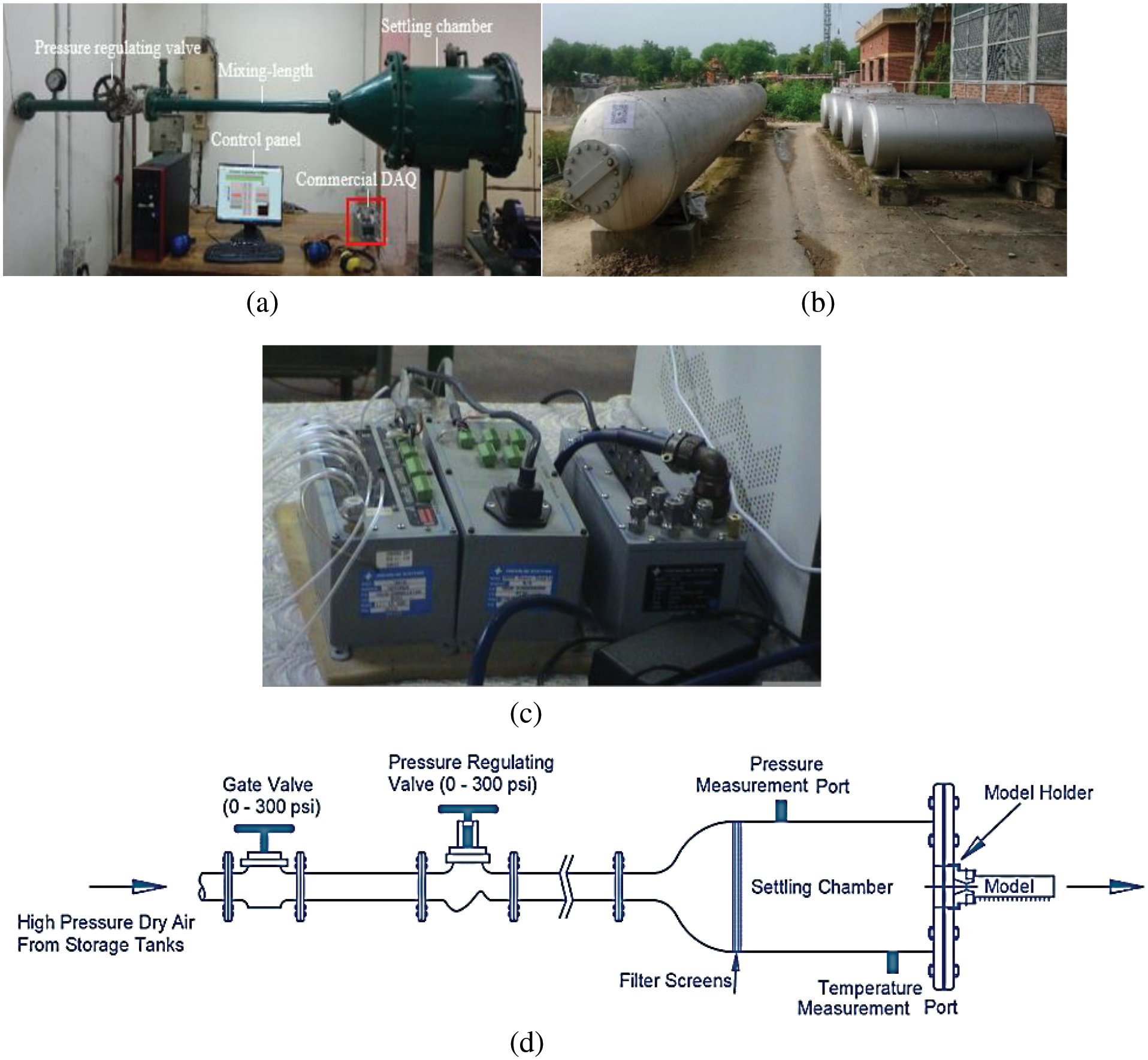

Figure 2: Experimental setup and configurations (a) Experimental setup (b) Storage tank (c) Pressure transducer (d) Schematic of the jet facility (e) Nozzle for M = 1.0 (f) Nozzle for M = 1.3 (g) Nozzle for M = 1.6 (h) Nozzle for M = 2.0
Pressure is recorded at the base, in the stagnation compartment, and inside the duct using the widely accessible commercial NetScannerTM Model 9116 pressure transducer, which is interfaced using 802.3 ethernets to the computer (Fig. 2d). Pressures up to 15 bar can be measured using its 16 channels. The transducer is interfaced with the computer using LabVIEW software. The sampling rate is 250 samples per second, and its average value is recorded on the hard disk. Three of the 16 channels are used to monitor pressure in the recirculation region, stagnation pressure, and pressure loss, and the rest of the channels measure pressure in the duct. A three-dimensional traverse was employed with a pitot probe that had its detecting hole facing the flow and had a resolution of ±0.1 mm to record stagnation pressure (Eq. (1)).
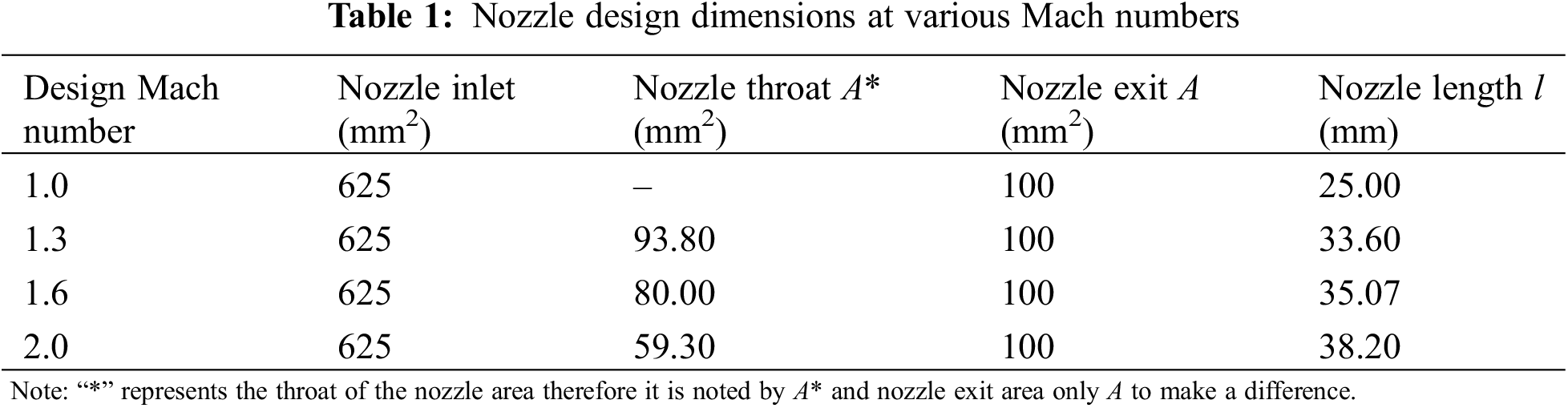
The diagrams of the nozzles created for Mach M = 1.0, M = 1.3, M = 1.6, and M = 2.0 are displayed underneath in Fig. 2e–h. These Nozzles for 4 Mach numbers have been fabricated based on isentropic conditions. The nozzle shape and other parameters have been concluded, and nozzles have been manufactured (Table 1).
The nozzle measurement rig is displayed in Fig. 3. The nozzle is attached to the stagnation compartment with the facility to vary the propelling pressure by hand at points of 0.1 bar. The pressure gauge attached to the settling compartment records the stagnation pressure P01. The total pressure is recorded by Pitot tube, P02, at the nozzle exit plane.

Figure 3: C–D nozzle calibration setup
Stagnation pressure ratio across the normal shock (P02/P01):
Substituting
Substituting M = 2 in Eq. (3),
Eq. (4) provides the ratio of total pressures, where P01 represents the upstream total pressure, and P02 happens following the typical shock. The total temperature continues to be constant across a normal shock.
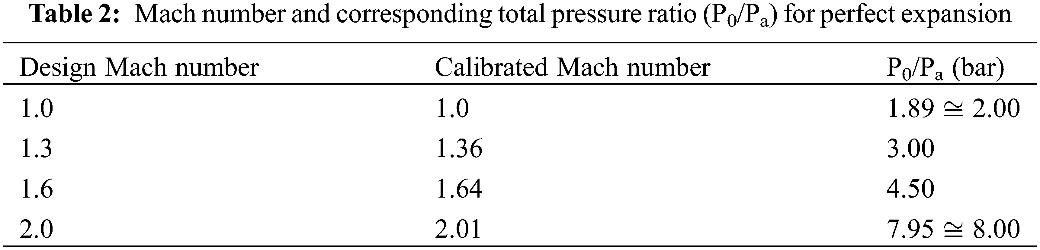
The flow is examined with and without control at four supersonic and sonic Mach values (Table 2). The pressure loss, base pressure, total pressure of the settling compartment, and pressure in the duct are all included in the calculations. A pitot tube was inserted in the center of the duct to measure the pressure loss and record the stagnation pressure there. The static pressure points along the duct are spaced equally between the duct outlet and the base zone. The purpose of the pressure points is to record the static pressure of the flow and assess how the rib affects flow development and whether the presence of the rib causes disturbances. The ambient pressure is divided by all measured pressures to normalize them. The square duct D’s sides give dimensionless to the pressure points’ positions.
Compressors are run until 14 bar of pressure is reached in the storage tanks for these tests. The necessary total pressure is provided by a gate valve, which also regulates the flow rate of air into the stagnation chamber. By attaching a measuring probe to the data acquisition (DAQ), NPR can be determined. Fig. 4 illustrates how a pitot tube is located at the tube exit to monitor loss in pressure. The probe is moved to the appropriate place using an x-y-z axes traverse mechanism. A threaded locking mechanism that makes removing and replacing the nozzle connects it to the settling chamber’s exit. Circular flanges on both ends of the duct join it to the nozzle. When the flanges are latched, a groove is carved out to secure the O-ring and prevent air leaks.

Figure 4: Nozzle associated with the duct with a pitot tube at the exit
The atmospheric pressure is added to the gauge pressure data obtained from the DAQ software to get absolute pressure (Fig. 5). Before beginning the runs, the DAQ system is calibrated to zero. The gauge pressure data from the DAQ software is combined with the daily atmospheric pressure to obtain absolute pressure. First, the DAQ logic is regulated to zero before starting the tests. The device gets the temperature and ambient pressure for the day to do zero calibration. The system treats the daily ambient pressure, or 1 atm, as zero, while the rest are evaluated as gauge pressures. Any channel can be turned on or off based on what is needed. Gauge pressure is used to measure all values. NPR is measured on channel 1, base pressure (Pb) is measured on channel 2, pressure loss through channel 3, and wall pressure (Pw) is measured on channels 4 through 16.

Figure 5: DAQ control panel
The result is a notepad file that can be easily calculated by converting to an Excel file. The results are expressed in m of Hg. The usual range of ambient pressure Pa, measured on testing days, is 0.741 to 0.745 m Hg. The quantities can be divided by ambient pressure to alter the unit to a bar, facilitating data interpretation. A reference book containing pressure data in m Hg and their equivalents in bar and gauge is employed during the runs. The base pressure vs. NPR plot of the results provides a thorough examination of the flow in the base region at various expansion levels. Likewise, duct static pressure is plotted against pressure tapping’s axial positions to comprehend static pressure variations inside the duct for a given expansion level. An open-jet compressed air plant served as the venue for the trials. Using a data collecting system, the pressure at the base and pressure in the conduit were recorded, and the various nozzles of different Mach numbers were tested for a range of NPRs. Plotting of pertinent graphs was done once the results were methodically collated.
The value that the mistake could have in a particular measurement is called uncertainty. Uncertainty is a statistical variable that can have a wide range of values. It is comparable to a values histogram. Although it is ideal to compute this uncertainty measure through repeated trials, it can instead be derived from estimates obtained entirely or in part from numerous experiments. An estimation of the errors related to the measured values is necessary. There is a description of the general process for calculating the uncertainty in the estimated amounts using measured data. The resulting generic expression has been used to illustrate the uncertainty estimation.
This section considers an approximation uncertainty approach for base pressure Pb. Base pressure control pressure Pbc, air pressure Pa, NPR, and P0/Pa affect the determined Pb base pressure. Thus,
With Eq. (5), the uncertainty in base pressure can be stated as:
To confirm the uncertainty, an estimate is shown for base pressure and determined for NPR = 5, M = 1.64, and area ratio 9. The ambient pressure equals 0.737 m of mercury (Hg). The settling compartment is 2.948 m of mercury (Hg) (gauge) and −0.587 of mercury (Hg) at NPR = 5 total pressure and the base pressure with control (gauge). Base pressure equals −0.632 m of mercury (Hg) (gauge) without regulation. We assume that the record of total pressure in the settling compartment, control chamber, and base pressure can have a maximum error of one inch. Eq. (6) determines the uncertainty by inserting the values for all the groupings of terms on the right-hand side. The base pressure ambiguity is ±2.403 percent.
The rib height (h) and rib locations (x) are expressed as fractions of the duct height. The duct height H has been chosen as 30 mm, while the rib heights h are 3, 5, and 7 mm, resulting in h/H = 0.10, 0.16, and 0.23, respectively. The schematic layout of the nozzle and duct is shown below in Fig. 6.
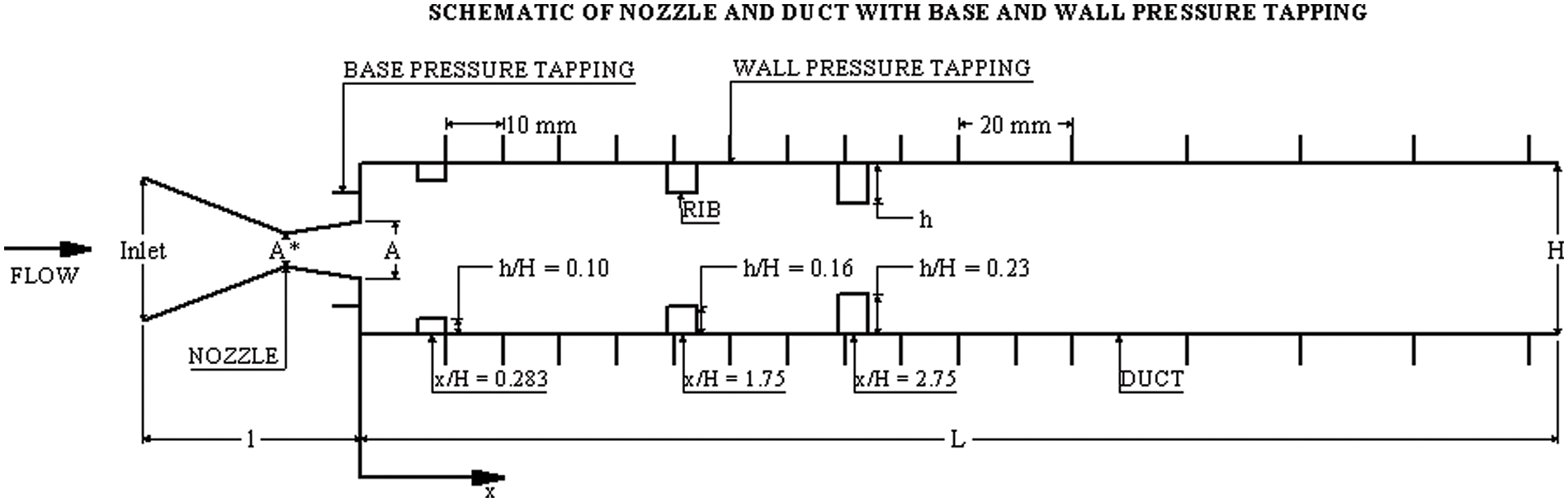
Figure 6: A view of the nozzle-duct
Base pressure Pb and duct static pressure Pw is normalized by parting them using atmospheric pressure. Base pressure is recorded at the duct’s base and is plotted against the NPR. These results were obtained for cases with and without ribs of various altitudes located at precise places in the tube. The pressure inside was also recorded and plotted against the duct length for different NPRs, rib height, and rib locations.
In Fig. 7, when the (L/D) ratio is 6, it is established that the base pressures at Mach of 1.0 increase significantly even though there is a progressive increase until NPR reaches 3. However, beyond NPR 3, the base pressure grows without any control condition. The phenomenon under observation may have its physics explained by the following. When the area effect surrounding the duct increases beyond a certain threshold, the nozzle flow that is exhausted into the expanded duct tends to stick to a length where the duct’s optimal size for a strong vortex in the base region is not met. The NPR impact on base pressure in the base area becomes negligible with a larger area ratio. Nevertheless, when the NPR equals or exceeds 3, the under-expansion level somewhat impacts the base pressure. Additionally, the control is significantly effective when the nozzle pressure ratio is more than 3.

Figure 7: Base pressure vs. NPR for M = 1.0 at different rib locations
When the Mach number was unity, there was a decrease in the base pressure when the ribs of three sizes were placed at three different locations; the control tends to decrease the base pressure. However, the magnitude of the decrease for various sizes of the ribs and locations was different. This low base pressure may benefit defense applications, as a combustion chamber must produce better fuel-air mixing and combustion efficiency. Authors recommend using these results if the application is for a combustion chamber. For an increase in the base pressure, results show that the rib’s height should be 4 to 6 mm.
Base pressure results for Mach 1.36 are shown in Fig. 8 for various rib heights for three different rib locations. From the Fig. 8a–c, it is evident that the flow pattern at supersonic Mach numbers is different. It is witnessed that the pressure in the recirculation region registers a substantial increase for cases with ribs beyond the NPR, which is associated with perfect expansion at the nozzle exit for any Mach number.
Figure 8: Base pressure vs. NPR for M = 1.36 at different rib locations
As discussed earlier, for this area ratio to attain a significant increase in the base pressure, the requirement of rib height is in the range of 4 to 6 mm. We infer this while analyzing the results in Fig. 8c that for maximum height of the ribs, there is an increase in the base pressure values, which increases more when nozzles are flowing under the influence of a favorable pressure gradient. These results reiterate that the control becomes effective when the nozzles are under-expanded. Also, the location of the rib should be 4D to 5D. The reattachment length should be around 120 to 150 mm for this area ratio.
Results for Mach 1.64 are shown in Fig. 9, which shows base pressure for three rib locations and heights. NPR for correct expansion, in this case, is NPR 4.5. The flow is said to be overexpanded for NPR values below 4.5, while it becomes under-expanded at NPRs beyond correct expansion. Base pressure steadily decreases as NPR increases to correct expansion and gradually increases under expanded conditions.
Figure 9: Base pressure vs. NPR for M = 1.64 at different rib locations
Fig. 9a presents the base pressure change through NPR in the existence of a rib for size h/H = 0.10 placed along the duct’s length at locations 0.283, 1.75, and 2.75 H. The data pertains to M = 1.64, for which NPR 4.5 is the threshold value for correct expansion at the exit of the nozzle. Beyond this NPR, the nozzle is under-expanded, and the base pressure rises. The % variation in base pressure with NPR increases by 19% at NPR 7 for a rib located at 1.75 H along the duct. Fig. 9b is for a rib of h/H = 0.16 with rib locations of 0.283, 1.75 and 2.75 H. However, a more significant change in base pressure of 33% is observed with the rib positioned at 2.75 H. For the rib height h/H = 0.23 placed along the duct, the changes in base pressure through NPR, as illustrated in Fig. 9c, is high, and the highest variation is 58%, with the rib positioned at 2.75 H. It is afterward suitable to accomplish that under-expanded nozzle discharging with a sudden increase in the area of the duct results in a base pressure increase when passive control is employed, and the base pressure continues growing with an increase in the expansion level once the nozzle becomes under-expanded. This growth is similarly more significant for the highest rib heights. The supersonic under-expanded nozzle exit waves reflected from the duct’s sides may significantly influence the pressure in the wake region by the tiny vortices created by the ribs acting as steps in the flow [16]. Base pressure build-up as high as 58% was witnessed when the control was in the form of ribs employed with the extreme rib length of 0.23 at 2.75 H. The ribs enhance pressure in the wake area, although refreshing when base drag reduction is desired, and advance to variabilities in static pressure inside the duct.
When jets are experiencing adverse pressure gradient, oblique shocks are created at the nozzle exit and reflected from the duct. A recirculation region is formed at the rib spot due to the making of derived vortices. The revealed shocks act with these subordinate vortices and probably reduce derived vortices’ consequences. Likewise, the expansion waves created at the nozzle exit when the nozzle undergoes a favorable pressure gradient augment the secondary vortices’ effect, rendering variations in static pressure and alterations in base pressure. At supersonic flow in a duct, the base pressure demonstrates a continuous reduction with a growing level of expansion without ribs.
Conversely, pressure in the duct rises quickly from the base pressure, realizing the back pressure at the duct. The induction of the rib into the duct has a substantial influence on the base pressure. Conversely, the rib creates vortices that act together with the vortex owed to the main jet. The findings are that static pressure variation inside the duct has variations, starting from the rib’s location in the duct. A few latest publications [16–18,27] have mainly focused on the effect of ribs on pressure at the base area whenever there is an abrupt rise in the area of the duct in the supersonic flow for ducts. During tests, we recorded pressure along the length of the duct. A rise or decline in base pressure substantially impacts the pressure in the duct when ribs are employed. The height of the rib plays a crucial part in manipulating base pressure variations. A constrained rib height could lead to feasible reattachment of the flow with the duct, thereby smoothening duct pressure.
Base pressure at Mach 2 is presented in Fig. 10. From the results; it is seen that for all the rib heights and locations, a decrease in the base pressure is noticed irrespective of expansion level. This means that the shock strength, reattachment length, and rib’s location and size are such that they create a strong suction in the base region. Under these conditions, the reverse flow from the shear layer and transfer to the primary is the reason for such low base pressure values.
Figure 10: Base pressure vs. NPR for Mach 2.01 at different rib locations
Whenever controls are employed, the researcher must observe the flow development in the duct. To ensure that the flow in the duct remains the same in the present study, the wall pressure along the duct was also measured.
The wall pressure was also plotted against the duct length for different NPRs, rib height, and rib locations. The deviation of wall pressure down the duct has a smooth increase in base pressure to ambient pressure at duct exit for NPR 4.5 and rib height of h/H = 0.10. There is a minimal deviation between the plots, whether the rib is present or absent at the chosen locations along the duct, as in Fig. 11. The maximum fluctuation is less than 5%. Increasing the NPR value to 7 (under expanded flow) introduces considerable fluctuations at rib locations, as seen in Fig. 12. The maximum deviation from the plot for no rib is also recorded as close to 20%. Similar observations have been presented for rib heights of h/H = 0.16 and h/H = 0.23 for cases of NPR 4.5 and NPR 7 in Fig. 13. The percentage fluctuations also rise to about 30%, corresponding to rib heights of h/H = 0.16 and h/H = 0.23, respectively. The pressure inside the duct was computed for all sequences of NPR, Mach (M), rib height (h), and rib positions in the duct. The assessment of these records shows pressure variations of the duct for under-expanded nozzles, and the flow exits into the duct as the pressure at the base corner grows. It is also observed for all rib altitudes positioned along the duct. The % variations are based on when ribs are employed and register 30% in some cases at some particular rib locations across the duct. Reasonably, the alterations are substantially significant with taller ribs, as seen in Fig. 14.
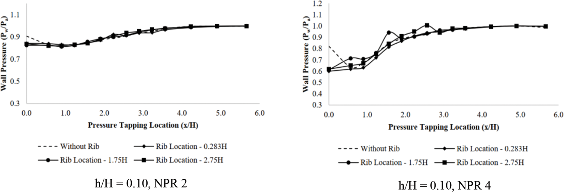
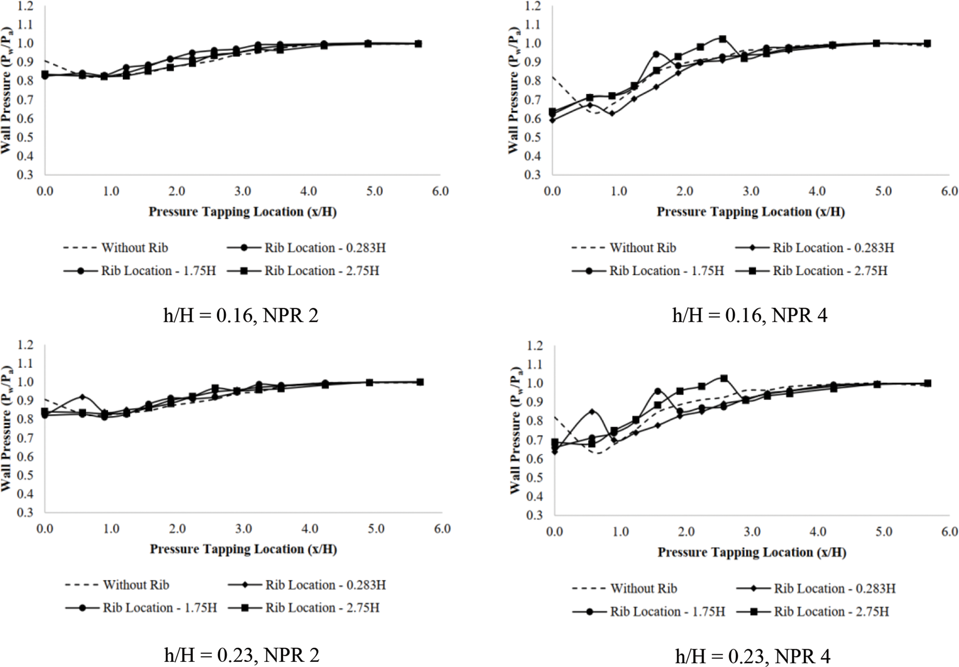
Figure 11: Wall pressure vs. x/H for Mach 1.0 at NPR 2 and NPR 4
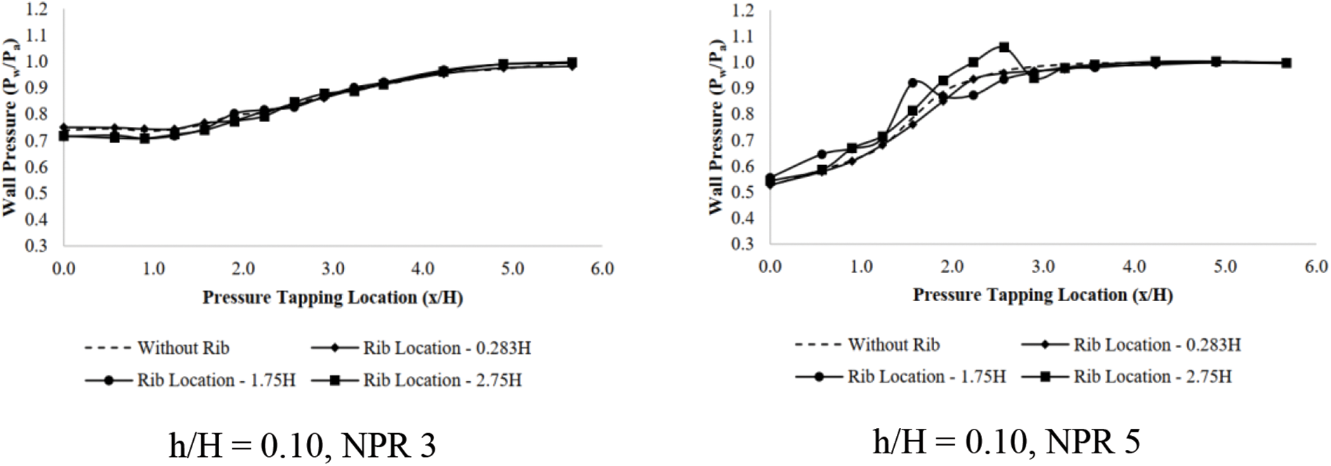
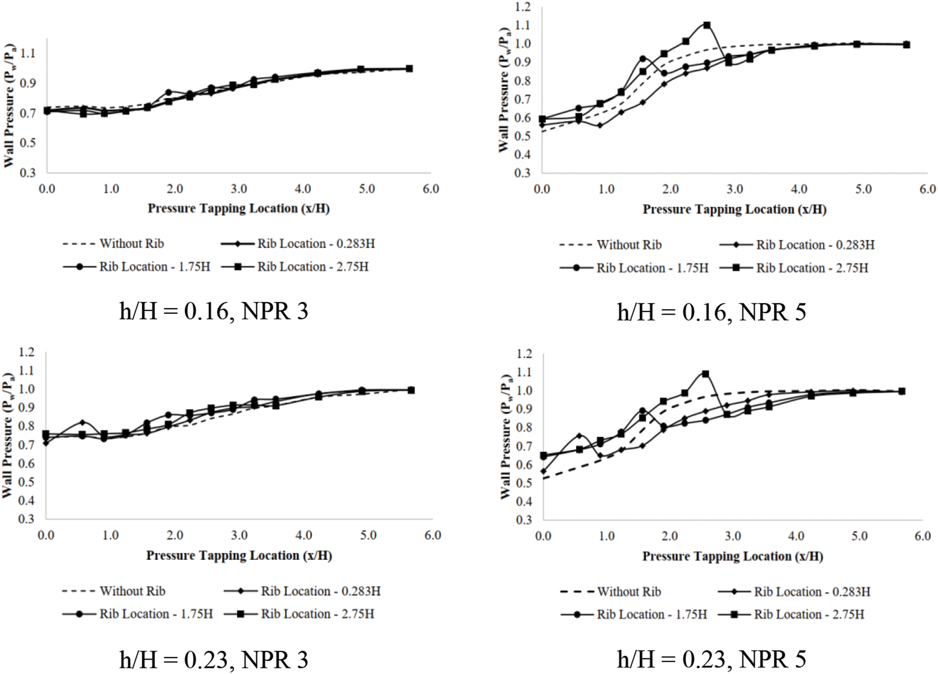
Figure 12: Wall pressure vs. x/H for Mach 1.36 at NPR 3 and NPR 5
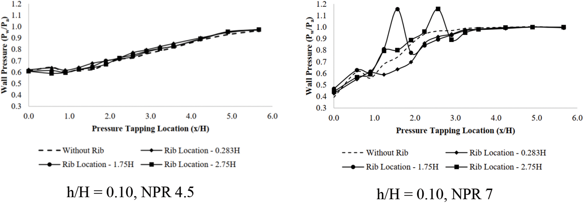
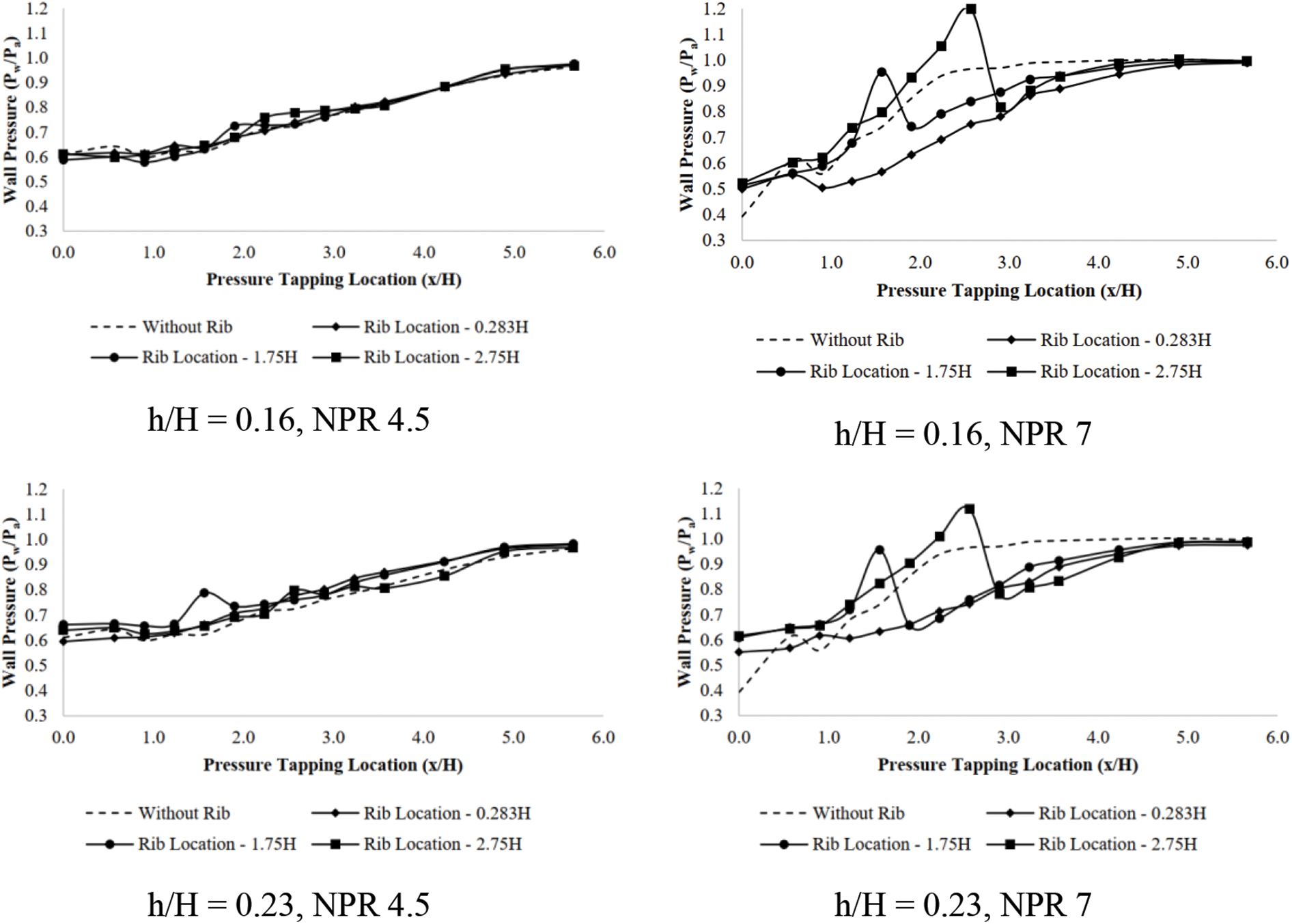
Figure 13: Wall pressure vs. x/H for Mach 1.64 at NPR4.5 and NPR 7
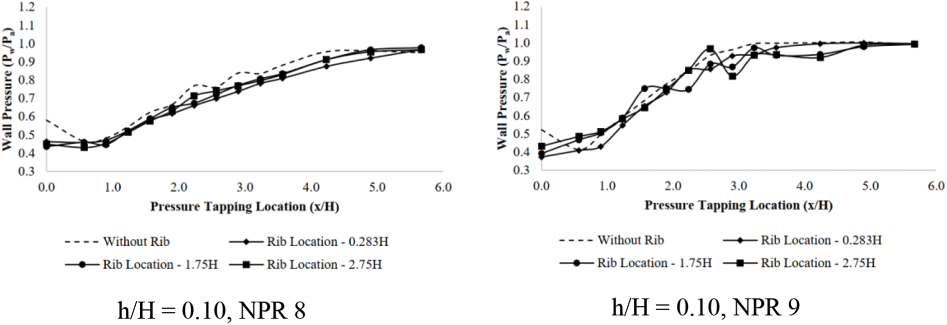
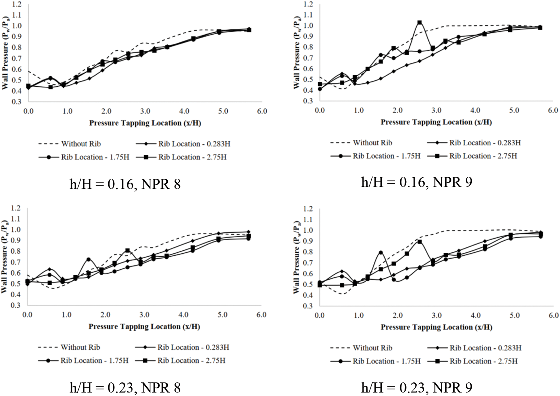
Figure 14: Wall pressure vs. x/H for Mach 2.01 at NPR8 and NPR 9
From the preceding considerations, we can infer the subsequent inferences:
• The experimental data indicates that, even with under-expanded jets, base pressure decreases once the area ratio is incredibly high. The reason for this trend may be related to physics: when the area ratio increases to a certain point, the relief effect it creates causes the nozzle flow aligned into the duct to converse with a length where the flow dividing streamlines are reattached that is not optimal for a powerful vortex at the base. Because of this procedure, the influence of the expansion level on base pressure becomes insignificant at larger area ratios. On the other hand, NPR = 6 and higher still affects the base pressure somewhat, and the control works quite well for supersonic Mach number M = 1.36.
• We may effectively regulate the base pressure in an enlarged duct at supersonic flow in the duct by adding ribs, which will boost the pressure by roughly 58%. At Mach 1.64, with ribs of altered heights placed along the duct’s length, the base pressure reduces with the growth in expansion level up to the level of expansion for threshold value for correct expansion at that Mach number. This translates into decreased base pressure with rising NPR in overexpanded flows.
• The base pressure gradually rises as soon as the nozzles are choked or slightly under-expanded, marking the start of the control. Whether active or passive control is used, these results confirm that control becomes effective once nozzles experience favorable pressure.
• When the flow is under-expanded beyond the NPR for appropriate expansion for any Mach number, the presence of ribs results in the base pressure rising with NPR.
• The wall static pressure inside the duct smoothly rises to duct exit atmospheric pressure in overexpanded nozzle flows for all Mach, rib altitudes, and rib localities.
• The wall static pressure along the duct exhibits fluctuations that increase with increasing rib heights in under-expanded flows. This limits the extent of base pressure increase desired in any combination of Mach (M), rib heights, and rib locations.
• As a compromise, providing a rib height of percent of the duct altitude in under-expanded supersonic flows in a duct will significantly increase base pressure without unnecessary rib variations.
Based on the experience gained through this study, it is recommended that we try our research on a minor diameter of the duct. With a decrease in the respite to the flow, the length where the flow gets reattached will decrease, and hence, passive control with ribs is expected to raise the base pressure manifold, resulting in a reduction in the base drag and, ultimately, a decrease in the net drag.
Acknowledgement: This research is supported by the Structures and Materials (S&M) Research Lab of Prince Sultan University, and the authors acknowledge the support of Prince Sultan University in paying the article processing charges (APC) for this publication.
Funding Statement: The authors received no specific funding for this study.
Author Contributions: The authors confirm their contribution to the paper as follows: study conception and design: Vigneshvaran Sethuraman, Parvathy Rajendran; data collection: Vigneshvaran Sethuraman, Sher Afghan Khan; analysis and interpretation of results: Parvathy Rajendran, Abdul Aabid, Muneer Baig; draft manuscript preparation: Vigneshvaran Sethuraman, Parvathy Rajendran. All authors reviewed the results and approved the final version of the manuscript.
Availability of Data and Materials: They are Available at the request of the corresponding author.
Conflicts of Interest: The authors declare that they have no conflicts of interest to report regarding the present study.
References
1. Wick RS. The effect of boundary layer on sonic flow through an abrupt cross-sectional area change. J Aeronaut Sci. Oct. 1953;20(10):675–82. doi:10.2514/8.2794. [Google Scholar] [CrossRef]
2. Korst HH. Comments on ‘The effect of boundary layer on sonic flow through an abrupt cross-sectional area change’. J Aeronaut Sci. Aug. 1954;21(8):568–9. doi:10.2514/8.3126. [Google Scholar] [CrossRef]
3. Sethuraman V, Khan SA. Base pressure control using micro-jets in supersonic flow regimes. Int J Aviat Aeronaut Aerosp. 2018;5(1). doi:10.15394/ijaaa.2018.1148. [Google Scholar] [CrossRef]
4. Chen L, Asai K, Nonomura T, Xi G, Liu T. A review of backward-facing step (BFS) flow mechanisms, heat transfer and control. Therm Sci Eng Prog. 2018;6(3):194–216. doi:10.1016/j.tsep.2018.04.004. [Google Scholar] [CrossRef]
5. Guo G-M, Liu H, Zhang B. Numerical study of active flow control over a hypersonic backward-facing step using supersonic jet in near space. Acta Astronaut. Mar. 2017;132:256–67. doi:10.1016/j.actaastro.2016.12.035. [Google Scholar] [CrossRef]
6. Sethuraman V, Khan SA. Effect of sudden expansion for varied area ratios at subsonic and sonic flow regimes. Int J Energy, Environ Econ. 2016;24(1):99–112. [Google Scholar]
7. Asadullah M, Khan SA, Asrar W, Sulaeman E. Low-cost base drag reduction technique. Int J Mech Eng Rob Res. 2018;7(4):428–32. doi:10.18178/ijmerr.7.4.428-432. [Google Scholar] [CrossRef]
8. Sajali MFM, Aabid A, Khan SA, Mehaboobali FAG, Sulaeman E. Numerical investigation of flow field of a non-circular cylinder. CFD Lett. 2019;11(5):37–49. [Google Scholar]
9. Pathan KA, Dabeer PS, Khan SA. Investigation of base pressure variations in internal and external suddenly expanded flows using CFD analysis. CFD Lett. 2019;11(4):32–40. [Google Scholar]
10. Khan A, Rajendran P, Sidhu JSS. Passive control of base pressure: a review. Appl Sci. 2021;11(3):1334. doi:10.3390/app11031334. [Google Scholar] [CrossRef]
11. Pandey KM, Rathakrishnan E. Annular cavities for base flow control. Int J Turbo Jet Engines. 2006;23(2):113–27. doi:10.1515/TJJ.2006.23.2.113. [Google Scholar] [CrossRef]
12. Rathakrishnan E, Ramanaraju OV, Padmanaban K. Influence of cavities on suddenly expanded flow field. Mech Res Commun. 1989;16(3):139–46. doi:10.1016/0093-6413(89)90051-7. [Google Scholar] [CrossRef]
13. Gharib M, Roshko A. The effect of flow oscillations on cavity drag. J Fluid Mech. Apr. 1987;177(11):501–30. doi:10.1017/S002211208700106X. [Google Scholar] [CrossRef]
14. Srikanth R, Rathakrishnan E. Flow through pipes with sudden enlargement. Mech Res Commun. 1991;18(4):199–206. doi:10.1016/0093-6413(91)90067-7. [Google Scholar] [CrossRef]
15. Kruiswyk RW, Duttont JC. Effects of a base cavity on subsonic near-wake flow. AIAA. 1990;28(11):1885–93. [Google Scholar]
16. Rathakrishnan E. Effect of ribs on suddenly expanded flows. AIAA J. Jul. 2001;39(7):1402–4. doi:10.2514/2.1461. [Google Scholar] [CrossRef]
17. Vijayaraja K, Elangovan S, Rathakrishnan E. Effect of rib on suddenly expanded supersonic flow. Int Rev Aerosp Eng. 2008;1(2):196–9. [Google Scholar]
18. Vijayaraja K, Senthilkumar C, Elangovan S, Rathakrishnan E. Base pressure control with annular ribs. Int J Turbo Jet-Engines. 2014;31(2):111–8. doi:10.1515/tjj-2013-0037. [Google Scholar] [CrossRef]
19. Khan A, Rajendran P, Sidhu JSS, Sharifpur M. Experimental investigation of suddenly expanded flow at sonic and supersonic Mach numbers using semi-circular ribs: a comparative study between experimental, single layer, deep neural network (SLNN and DNN) models. Eur Phys J Plus. 2023;138(4):1–25. doi:10.1140/epjp/s13360-023-03853-1. [Google Scholar] [CrossRef]
20. Mariotti A, Buresti G, Salvetti MV. Separation delay through contoured transverse grooves on a 2D boat-tailed bluff body: effects on drag reduction and wake flow features. Eur J Mech B/Fluids. 2019;74(11):351–62. doi:10.1016/j.euromechflu.2018.09.009. [Google Scholar] [CrossRef]
21. Ridwan, Afghan Khan S, Syed Mohamed Ali J, Azan Mohammed Sapardi M, Aabid A. Numerical analysis of cavity-based control of base pressure variations at supersonic Mach numbers. Fluid Dyn Mater Proc. 2023;19(6):1655–78. doi:10.32604/fdmp.2023.025230. [Google Scholar] [CrossRef]
22. Husnina N, Zuraidi M, Khan SA, Aabid A, Baig M. Passive control of base pressure in a converging-diverging nozzle with area ratio 2.56 at Mach 1.8. Fluid Dyn Mater Proc. 2023;19(3):807–29. doi:10.32604/fdmp.2023.023246. [Google Scholar] [CrossRef]
23. Dennis Quadros J, Afghan Khan S, Aabid A, Baig M. Modeling and validation of base pressure for aerodynamic vehicles based on machine learning models. Comput Model Eng Sci. 2023;137(3):2331–52. doi:10.32604/cmes.2023.028925. [Google Scholar] [CrossRef]
24. Al-Khalifah T, Aabid A, Khan SA, Bin Azami MH, Baig M. Response surface analysis of nozzle parameters at supersonic flow through microjets. Aust J Mech Eng. 2023;21(3):1037–52. doi:10.1080/14484846.2021.1938954. [Google Scholar] [CrossRef]
25. Aabid A, Khan SA. Investigation of high-speed flow control from CD nozzle using design of experiments and CFD methods list of symbols. Arab J Sci Eng. 2021;46:2201–30. doi:10.1007/s13369-020-05042-z. [Google Scholar] [CrossRef]
26. Aabid A, Khan SA, Afzal A, Baig M. Investigation of tiny jet locations effect in a sudden expansion duct for high-speed flows control using experimental and optimization methods. Meccanica. 2021;6(1):17–42. doi:10.1007/s11012-021-01449-6. [Google Scholar] [CrossRef]
27. Khan A, Rajendran P, Sarjit J, Sidhu S. Convolutional neural network modeling and response surface analysis of compressible flow at sonic and supersonic Mach numbers. Alexandria Eng J. 2022;65(5):997–1029. doi:10.1016/j.aej.2022.10.006. [Google Scholar] [CrossRef]
Cite This Article
 Copyright © 2024 The Author(s). Published by Tech Science Press.
This work is licensed under a Creative Commons Attribution 4.0 International License , which permits unrestricted use, distribution, and reproduction in any medium, provided the original work is properly cited.
 Downloads
 Citation Tools