
 Submit a Paper
 Propose a Special lssue
 Open Access
ARTICLE
Study of a Hydraulic Jump in an Asymmetric Trapezoidal Channel with Different Sluice Gates
1 Research Laboratory in Civil Engineering, Hydraulics, Sustainable Development and Environment (LARGHYDE), University of Biskra, Biskra, 7000, Algeria
2 Faculty of Sciences Applied Sciences, Liege University, Liege, 4000, Belgium
3 Underground and Surface Hydraulics Research Laboratory (LARHYSS), Biskra, 7000, Algeria
* Corresponding Author: Bouthaina Debabeche. Email:
Fluid Dynamics & Materials Processing 2024, 20(7), 1499-1516. https://doi.org/10.32604/fdmp.2024.047403
Received 04 November 2023; Accepted 06 February 2024; Issue published 23 July 2024
 View Full Text
 Download PDF
Abstract
In this study, the main properties of the hydraulic jump in an asymmetric trapezoidal flume are analyzed experimentally, including the so-called sequent depths, characteristic lengths, and efficiency. In particular, an asymmetric trapezoidal flume with a length of 7 m and a width of 0.304 m is considered, with the bottom of the flume transversely inclined at an angle of m = 0.296 and vertical lateral sides. The corresponding inflow Froude number is allowed to range in the interval (1.40 < F1 < 6.11). The properties of this jump are compared to those of hydraulic jumps in channels with other types of cross-sections. A relationship for calculating hydraulic jump efficiency is proposed for the considered flume. For F1 > 5, the hydraulic jump is found to be more effective than that occurring in triangular and symmetric trapezoidal channels. Also, when mes > 8 and > 5, the hydraulic jump in the asymmetrical trapezoidal channel downstream of a parallelogram sluice gate is completely formed as opposed to the situation where a triangular sluice is considered.Keywords
Nomenclature
| At | Area of the water outlet of the sluice gate, m² |
| D | Transverse difference in bed elevation, m |
| F1 | Inflow Froude number |
| g | Acceleration of gravity, m/s2 |
| h0 | Difference in water depth between the deeper and the shallow side, m |
| h1 (c) | Initial height of the water on the centerof the channel width, m |
| h1 (d) | Initial height of the water on the deeper side of the channel width, m |
| h1 (s) | Initial height of the water on the shallow side of the channel width, m |
| H1 | Charge in the first section of the hydraulic jump, m |
| h1ave | Average depth of upstream sequences, m |
| h2 (c) | Final height of the water on the center of the channel width, m |
| h2 (d) | Final height of the water on the deeper side of the channel width, m |
| h2 (s) | Final height of the water on the shallow side of the channel width, m |
| H2 | Charge in the last section of the hydraulic jump, m |
| h2ave | Average depth of downstream sequences, m |
| hv | Height of the sluice gate, m |
| l | Channel width, m |
| L | Channel length, m |
| Lr(d) | Length of the roll on the deeper side, m |
| Lr(s) | Length of the roll on the shallow side, m |
| M | Parameter, M = mh/b, |
| m | Transverse inclination of the channel bottom concerning the horizon |
| Q | Flow discharge, m3/s |
| x0 | Width of the cross section, m |
| Y | Sequent depths |
| ΔH | Loss energy, m |
| Δy | Height of the downstream lift gate, m |
| η | Efficiency of the hydraulic jump, % |
| | Ratio of length of the roll on the shallow side and h2−h1 |
| | Ratio of the length of the roll on the deeper side and h2 ave |
| | Ratio of the length of the roll on the shallow side and h2 ave |
A hydraulic jump primarily dissipates excessive kinetic energy from flow downstream, which has been frequently observed in hydraulic structures such as spillways and sluice gates. The hydraulic jump is an intriguing and interesting phenomenon that has attracted the attention of many researchers since it was first characterized by Leonardo Da Vinci in the 1500s [1]. For more than 300 years, the myth of hydraulic jump has not been well explained by researchers. Until 1818 [2], an Italian engineer Bidone appeared and conducted the first test to investigate this phenomenon. However, Chanson [3] recently claimed that future research in aerated flow hydraulics should focus on high-quality field measurement, development of new measurement approaches and data analysis tools, computational fluid dynamics modeling of aerated flows, and mechanics of aerated flows in conduits.
The hydraulic jump has been defined in several studies. For example, Sinniger et al. defined the hydraulic jump in free surface flow as a sudden transition from supercritical to subcritical flow [4], characterized by a important turbulence, intense air entrainment and signifcant fuctuations in the velocity and pressure felds [5]. These turbulences cause a significant loss of energy [6], which becomes the operating principle of all water flow energy dissipators. Flows on the free surface at high speeds are complex multiphase flow motions observed in natural water systems such as breaking waves, torrents, bores, and hydraulic structures.
Many scholars have contributed to the analysis of the free surface flow discontinuity, including Darcy and Bazin, Bresse, and Unwin. They described the phenomenon in detail and discussed its length [7]. High-velocity water flow energy dissipators were required in the framework of large dam development during the twentieth century, specifically in 1930. A hydraulic jump in a stilling basin effectively dissipates excess kinetic energy downstream of large dam spillway chutes, which contributed to a significant design improvement. In 1992, Hager [8] for the first time published a book on the design of energy dissipators, and the author presented the state-of-the-art hydraulic jumps and associated stilling basins, as well as design criteria and recommendations. Over the last two decades, the research on this topic has steadily expanded due to technological advancements in measurement tools and calculation programs. Several recent studies have been carried out on the hydraulic jump, such as the study Kim et al., which investigated flow turbulence and pressure fluctuations in a hydraulic Jump [9]. A numerical modelling of negative steps hydraulic jumps was carried out by Macián-Pérez et al. to improve energy dissipation in stilling basins [10].
Fig. 1 depicts a typical lateral view of a hydraulic jump and describes its key geometric and flow parameters. F1 is the inflow Froude number of upstream of the hydraulic jump. In the case of a rectangular channel with a constant width b (m), the application of the momentum principle between the upstream (1) and downstream (2) sections of a fixed location where hydraulic jump occurs with a constant discharge Q (m³/s) leads to the following relation among the main flow variables [1,4]:
where g (m/s2) is the acceleration due to gravity; h1(m) is the inflow depth and V1(m/s) is the inflow velocity, equal to Q/A (A(m²)-the flow cross section). Eq. (1) assumes a hydrostatic pressure distribution in Sections 1 and 2, i.e., negligible transverse and span wise flow velocities compared to streamwise one. It also neglects bottom slope and friction effects due to the short hydraulic jump length (i.e., abrupt flow depth variation).
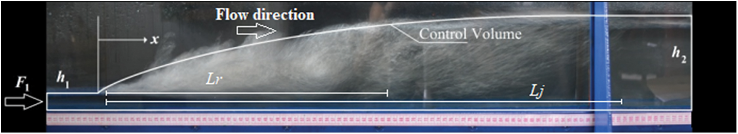
Figure 1: Side view of a hydraulic jump and main variables [9]
F1[-] denotes the inflow Froude number (
Mavis and Luksch in 1936 found that the characteristic length
The efficiency η[-] of the hydraulic jump is defined by the ratio of the head loss ∆H from side to side of the jump to the upstream head H1 [4]:
where H = h +
Sinniger et al. proposed the following general equation to compute the efficiency of a hydraulic jump [4]:
Eq. (4) can be simplified for a rectangular section into
The jump roller length Lr is the longitudinal distance over which the water elevation increases monotonically [3]. Hager et al. proposed a correlation for the roller length on a smooth bed [13]:
Trapezoidal open channels are commonly used to transport water in irrigation systems, drainage ditches, and stormwater management systems [14,15]. Wanoschek et al. [16] studied symmetrical trapezoidal channels and Rodriguez-Diaz [17] studied asymmetrical trapezoidal channels. Both showed that a hydraulic jump is more effective (i.e., greater energy dissipation) in a non-rectangular channel than in a rectangular channel for the same upstream flow conditions (equal F1 and h1 values).
Hager et al. studied the hydraulic jump in symmetrical triangular channels. They provided the following modified Belanger equation for the sequent depth of the hydraulic jump taking place in a symmetrical triangular channel with a 90° angle between side walls for 2 < F1 < 13.5 [18], with h1 and h2 measured at the center of the section:
Debabeche et al. studied the hydraulic jump in symmetrical triangular channels with a 90° opening angle, with a slope angle between the walls (m = 0.03), b = 0.5 m and 3.61 < F1 < 12.98. These authors determined the effect of the channel’s slope on the sequent depth ratio of the jump [19].
Roushanger et al. evaluated the effects of channel geometry and rough boundary conditions in predicting the hydraulic jump energy dissipation using a support vector machine (SVM) as a meta-model approach [20]. Their study showed that the Froude number had the most significant impact on the modeling result. Also, the same authors [20], applied an Adaptive Neuro-Fuzzy Inference System (ANFIS) as a Meta model approach to estimate hydraulic jump characteristics in the channels with different bed conditions. They found that the basin with a rough bed in rectangular channels showed better predictions of jump length than the basin with a step.
Although Rodriguez-Diaz first considered the hydraulic jump formed in an asymmetrical trapezoidal channel [17], Kiri et al. [21], Fig. 2 conducted a new series of tests on this type of cross-section after over half a century. However, the number of studies focusing on this specific topic remains limited. This paper aims to contribute to the documentation of hydraulic jump properties in an asymmetrical trapezoidal channel whose side walls are vertical with transversally inclined bottoms.
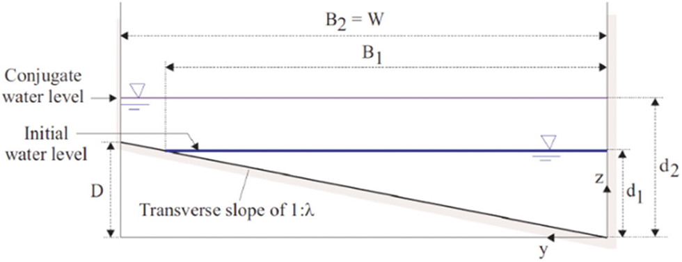
Figure 2: Definition of notations from side to side of a hydraulic jump in an asymmetrical trapezoidal cross-section (adapted from Kiri et al., 2020) [21]
Rodriguez-Diaz studied the conditions of the hydraulic jump formation and its characteristic length and conjugate height ratio. The channel width was varied at constant transverse bottom slope and three locations on the width of the channel have been defined: the shallow side, the center, and the deeper side [17].
According to Rodriguez-Diaz [17], two different types of flow exist Fig. 3: Undulating waves through the channel and rollers on the shallow side. A well-defined second wave has always been observed (Figs. 3a and 3b); A wave perpendicular to the cross-section, which can be called a hydraulic jump; no second wave was observed (Figs. 3c and 3d). So, there were two different types of flow. The first is an undulating wave Figs. 3a and 3b whose ratio
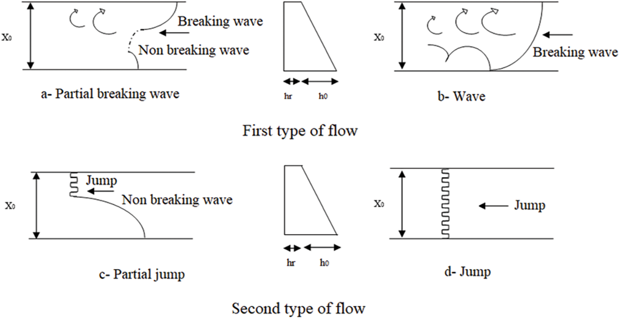
Figure 3: General diagram of the flow in an asymmetric channel [17]
The relationship between the length of the roller at both sides of the channel (shallow and deep) and the width of the inclined bottom of the channel has also been studied by Rodriguez-Diaz (1954) [17]. According to this study, there is a positive correlation between the width of the channel and the length of the roller on the shallow side. And an inverse relationship on the deep side of the channel. The inverse relationship between the flow length on the deep side and the channel width is explained by the influence of the channel bottom on the flow length. As the channel width decreases, the channel bottom slope becomes smaller. The length of the roller reaches its limit when it is equal on both sides of the channel (shallow and deep), as in a rectangular channel.
Also, the average of the maximum values of the ratio
Kiri et al. focused on velocity and free-surface elevation measurements to characterize unsteady three-dimensional flow transverse mixing processes. Steady flow characterization in the asymmetrical bed configuration indicated the presence of secondary motion and transverse momentum transferred the shallow-water section to the deep-water section [21].
This study considered a trapezoidal asymmetrical channel with vertical side walls and transversally inclined bottom. The aims of the research were to i) complement the description of the phenomenon of hydraulic jump in such a specific channel type, ii) analyze the main properties of the jump, including the sequent depths and characteristic lengths, and compare them with other types of channels, iii) and finally, to propose a relation to calculate the efficiency of the hydraulic jump in an asymmetric trapezoidal channel.
The specific canal geometry we designed gives originality to our work. We deliberately studied downstream of two gates to expand the circle of study. The experiment was carried out at the Laboratory of Civil Engineering and Hydraulics (Biskra-Algeria), and the measuring equipment was supplied by HECE (Liege-Belgium).
The model is briefly described in the next section, followed by a result presentation and discussion.
The experimental setup was a horizontal straight channel Figs. 4 and 5a with length L = 7 m and width b = 0.304 m with an asymmetric trapezoidal cross-section. The side walls were vertical, but the bottom was transversally inclined at an angle of m = 0.296 to the horizontal Fig. 5b. Water was supplied to the channel using a pump with a circular pipe connected to a reservoir. The water entered the channel through a sluice gate at the reservoir bottom. Three sluice gates were tested: a triangular and two parallelogram ones. In each case, the gate bottom overlapped with the channel bottom. The vertical opening heights of the parallelogram sluice gates were 0.04 and 0.06 m, respectively, while the maximum height of the triangular sluice gate was 0.07 m Fig. 6.
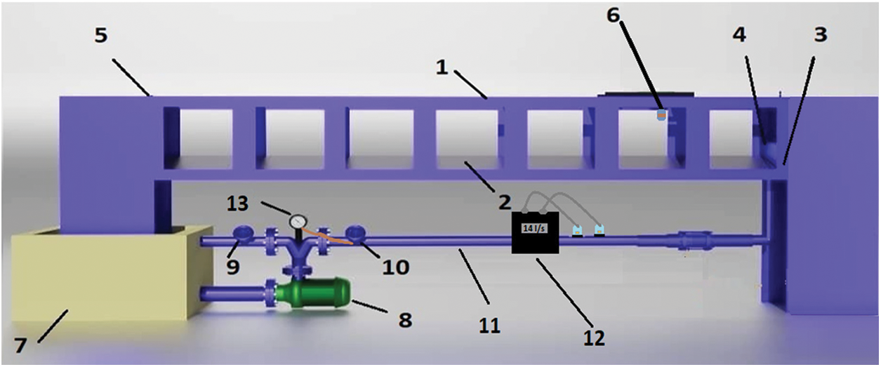
Figure 4: Simplified diagram of the flume used for the experimentation
Note: 1-Asymmetrical trapezoidal channel; 2-Inclined bottom in plexiglass (m = 1/3); 3-Steel panels; 4-Upstream sluice gate: (parallelogram or triangular); 5-Downstream lifting gate; 6-Ultrasonic probes; 7-Tank; 8-Axial centrifugal pump; 9-Discharge gate; 10-Flow control gate; 11-PVC pipe; 12-Utrasonic flowmeter; 13-Barometer.
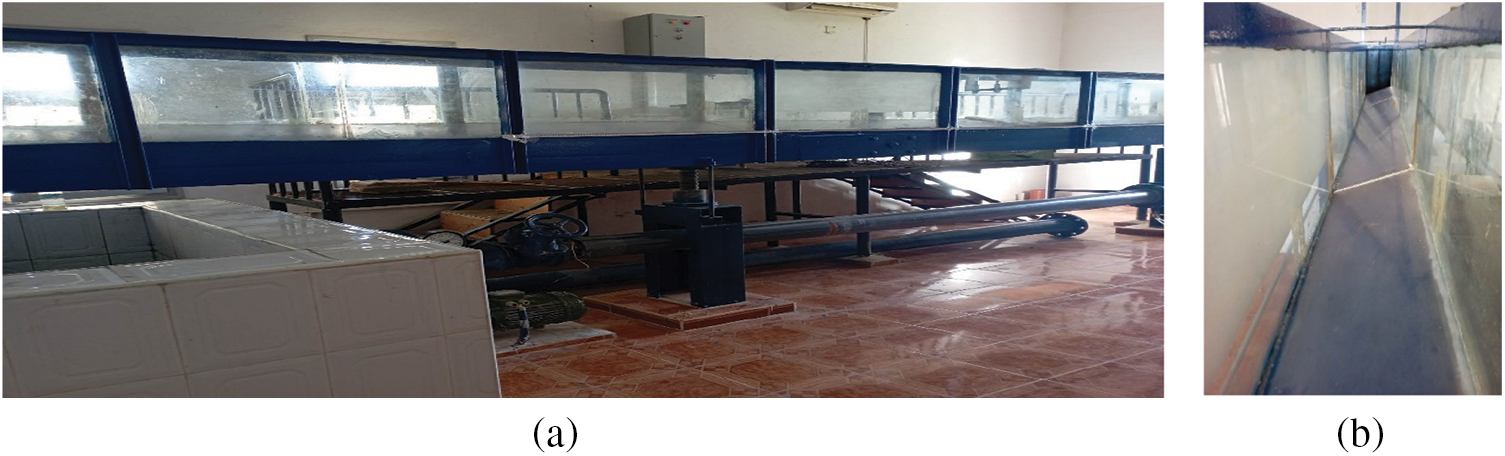
Figure 5: (a) Model used for experimentation; (b) bottom of the channel
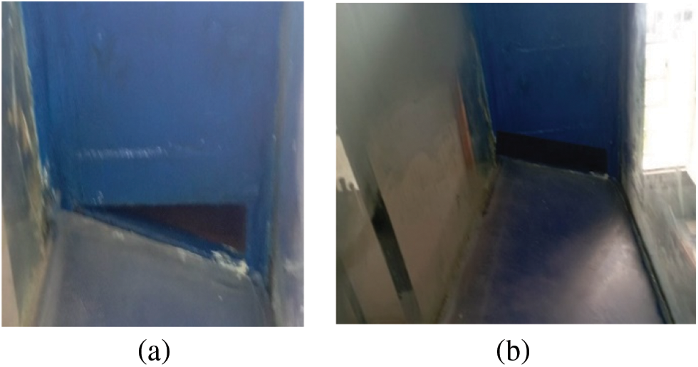
Figure 6: Upstream sluice-gates (a) triangular; (b) parallelogram in an asymmetrical trapezoidal channel
A trapezoidal lift gate was placed at the downstream end of the asymmetric trapezoidal channel to adjust the water depth in the channel and thus to fix the location of the hydraulic jump.
The flow rate was measured using an ultrasonic flowmeter (Minisonic II, Ultraflux) with an accuracy of 0.05l/s. Discharge varied from 0.0145 to 0.0333 m3/s.
Three ultrasonic probes (US) (Microsonic) were used to measure the water depths at hydraulic jump extremities with an accuracy of 1 mm. Measures were done along both sides of the channel and on the centerline. Given the strong free surface fluctuations during the tests, measures were carried out during the 150 s with a frequency of 1 Hz and averaged values were computed.
The upstream water depth measurement section corresponds to the beginning of the hydraulic jump at the abscissa x1 = 2.50 m from the upstream gate. Based on previous experience, this distance was chosen for an adequate long distance between the upstream sluice gate and the beginning of the hydraulic jump so that the hydraulic jump stabilizes and forms completely. The downstream measurement section was located at abscissa x2 = 5.50 m. This abscissa is after the end of the hydraulic jump for all the tests on both sides of the channel (i.e., shallow and deep sides).
The roller length was measured on both shallow and deeper sides of the channel using dye [22]. The dye was poured onto the jump surface at different abscissa to highlight the flow direction and then located the end of the upstream oriented surface flow velocities, i.e., the end of the roller Fig. 7.
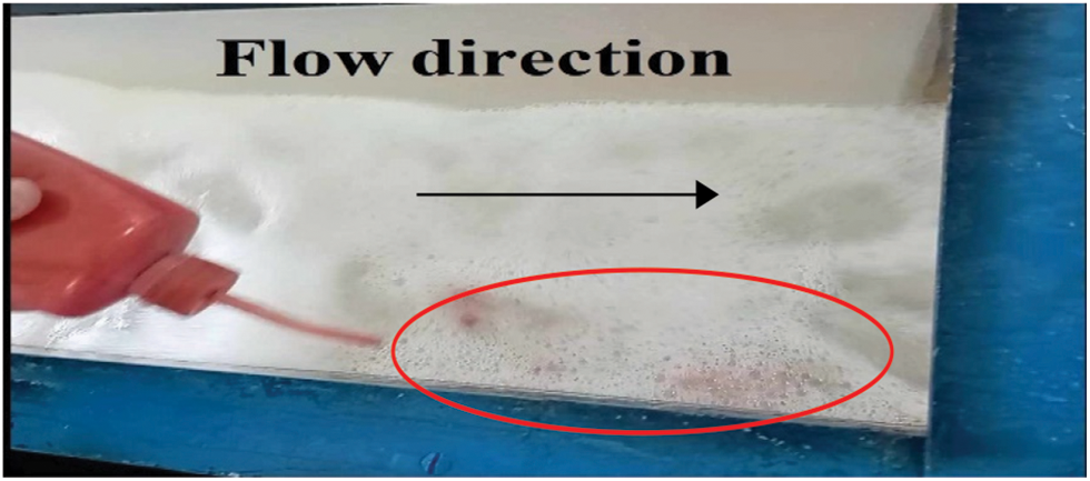
Figure 7: Determination of Lr by dye experiment in an asymmetrical trapezoidal channel
A large range of inflow Froude numbers F1 was tested, varying from 1.40 to 6.11 depending on the upstream sluice gate (Table 1).
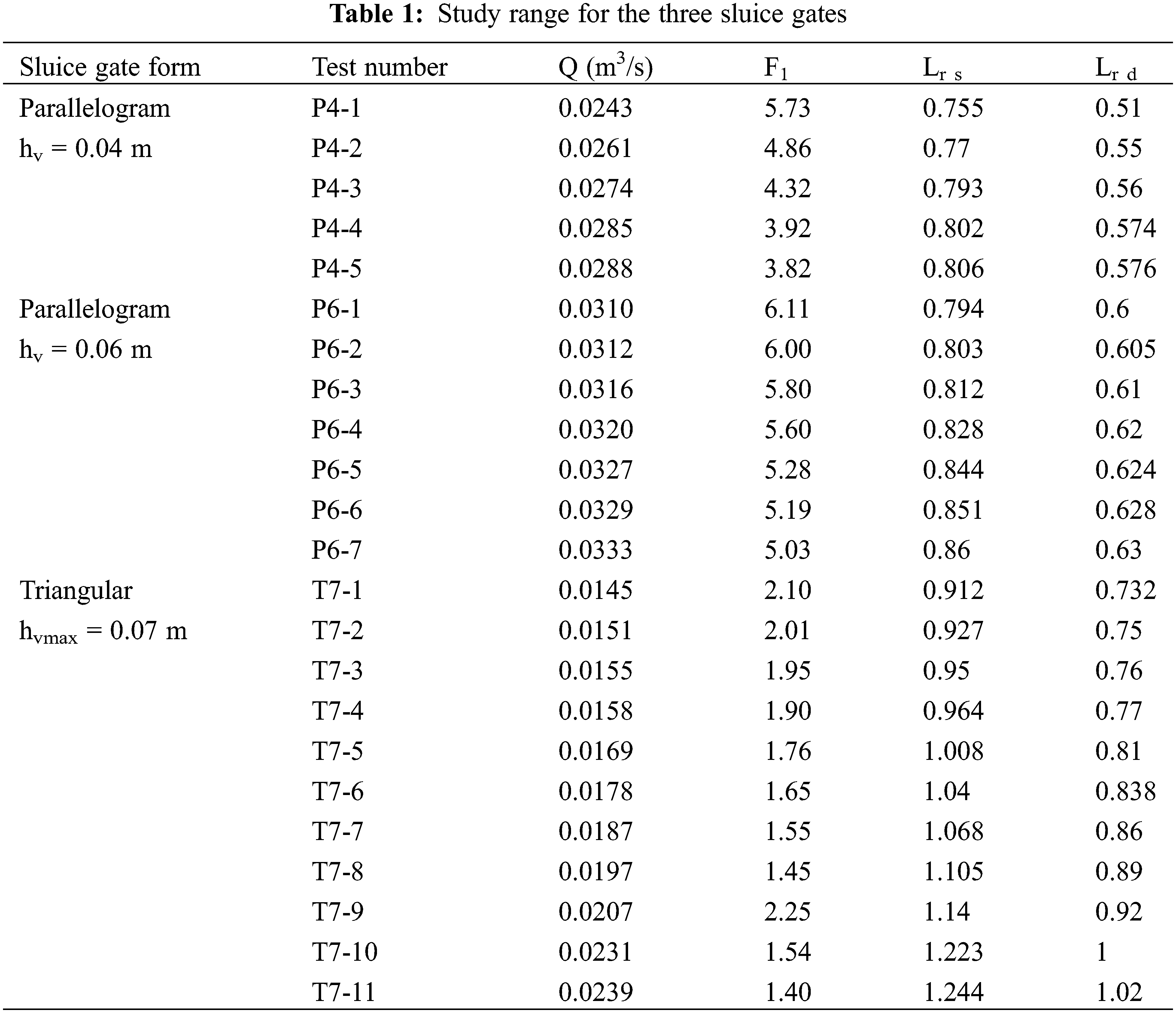
The general expression of the inflow Froude number is:
Using the hypothesis that the free surface upstream of the hydraulic jump is almost horizontal transversally, we find:
where D is the transverse difference in bed elevation (D = 0.09 m); h1d represents the height of the water measured on the deep side of the width of the channel and h1ave represents the average of the water depth measured at the toe of the hydraulic jump (3 positions on channel width).
The following procedure was applied for all tests:
• Stabilization of a discharge Q
• Stabilization of the hydraulic jump toe at abscissa 2.50 m using the downstream gate
• Measure of discharge Q
• Measure of the roller length Lr on shallow and deep sides of the channel using dye
• Measure of water depths h1 at 2.50 m and h2 at 5.50 m on shallow and deep sides as well as on channel center.
3.1 Description of the Phenomenon
As shown in Fig. 8a, the flow between the upstream sluice gate and the beginning of the hydraulic jump is not homogeneous over the width of the channel, due to the asymmetrical cross-section. Close to the injection zone, upstream of the channel, the flow does not use the whole width of the channel because of the transverse slope of the channel bottom. However, for each test, the hydraulic jump toe was normal to the channel axis and occupied the whole channel width Fig. 8b.
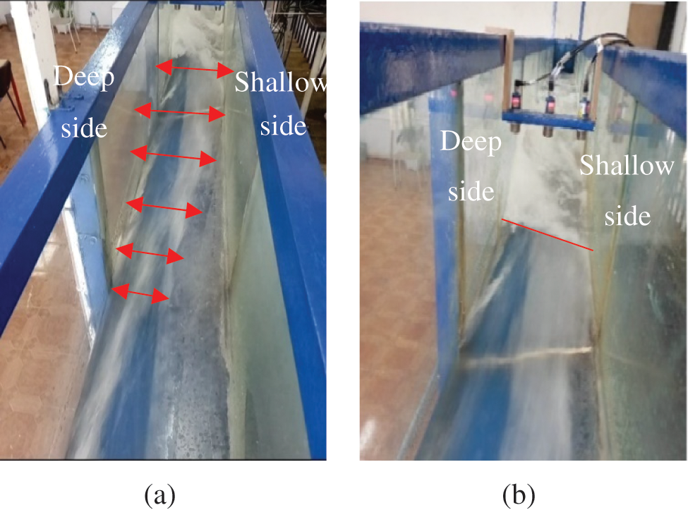
Figure 8: Transverse view of a hydraulic jump in an asymmetrical trapezoidal channel (a) Flow near the triangular sluice gate (T7), F1 = 2.1; (b) Hydraulic jump; parallelogram sluice gate (P4), F1 = 3.9
If we compare the hydraulic jump shown Fig. 8b with the classification proposed by Rodriguez-Diaz [17] Fig. 3, it corresponds to a complete jump Fig. 3d.
A hydraulic jump is shown schematically in Fig. 9. It is formed in an asymmetrical trapezoidal channel and exhibits geometric and flow feature variations in the three directions. Roller length varies from side to side of the channel, with roller length longer on the shallow side than on the deep side.
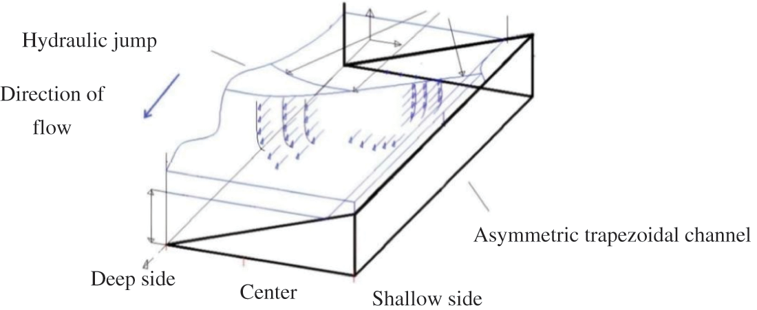
Figure 9: Schematic of hydraulic jump in an asymmetric trapezoidal channel-cross sectional view
Kiri et al. suggested that the water plane is horizontal on the transversal section, upstream and downstream of the jump [21]. Sequent depth Y has been computed as the ratio of the averaged h2 and h1 values measured on the shallow side, the channel center and the deep side.
Fig. 10 illustrates the sequent depths ratio Y variation as a function of the inflow Froude number F1 for different cases, including rectangular channel studied by Chachereau et al. [23], rectangular channel with step studied by Roushangar et al. [20], values derived from the Belanger equation (rectangular channel Eq. (2) [11], triangular channel Eq. (7)) and the present study (asymmetric trapezoidal channel with triangular and parallelogram upstream gates).
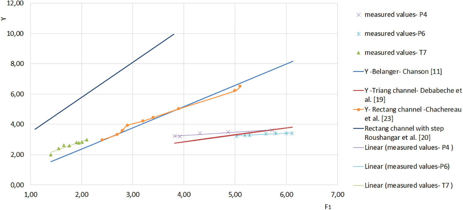
Figure 10: Sequent depths ratio Y of the hydraulic jump as a function of inflow Froude number for three sluice gates; Belanger; rectangular channel, rectangular channel with step and triangular channel (α = 90°)
From Fig. 10, for the same inflow Froude number, the increase in Y for measured values in an asymmetric trapezoidal channel with a triangular sluice gate is greater than in the rectangular channel. However, the opposite is true for Y in the asymmetric trapezoidal channel with a parallelogram sluice gate. Also, the values of Y for a triangular channel are between those of the two parallelogram gates in the asymmetrical trapezoidal channel. Also, the increase in Y for rectangular channel with step is greater than for all other cases.
As a result, for 1.4 < F1 < 6.11, the asymmetrical trapezoidal channel with a parallelogram sluice gate reduces the height of the hydraulic jump more than its homolog with a triangular sluice gate and the rectangular channel, but this is not the case for a rectangular channel with a step.
Fig. 11 illustrates the characteristic length
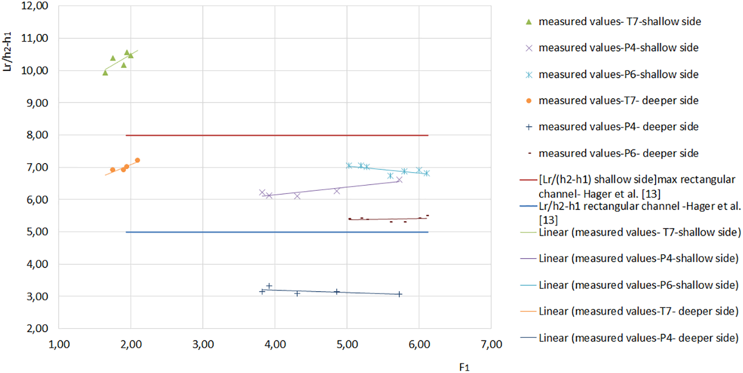
Figure 11: Relative lengths
Mavis and Luksch in 1936 found that the characteristic length
Bakhmeteff and Matzke in 1936 obtained the maximum values of
Fig. 12 illustrates the characteristic length
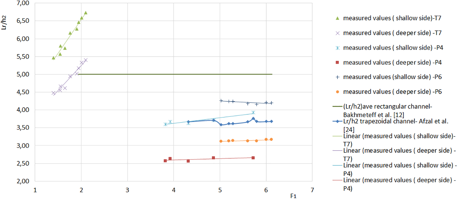
Figure 12: Relative lengths
According to reference [24], the length of the roll
According to [8], the characteristic length
Based on Figs. 11 and 12, the ratios are:
Moreover, according to the study of the hydraulic jump given by Rodriguez-Diaz [17], the hydraulic jump is completely formed when
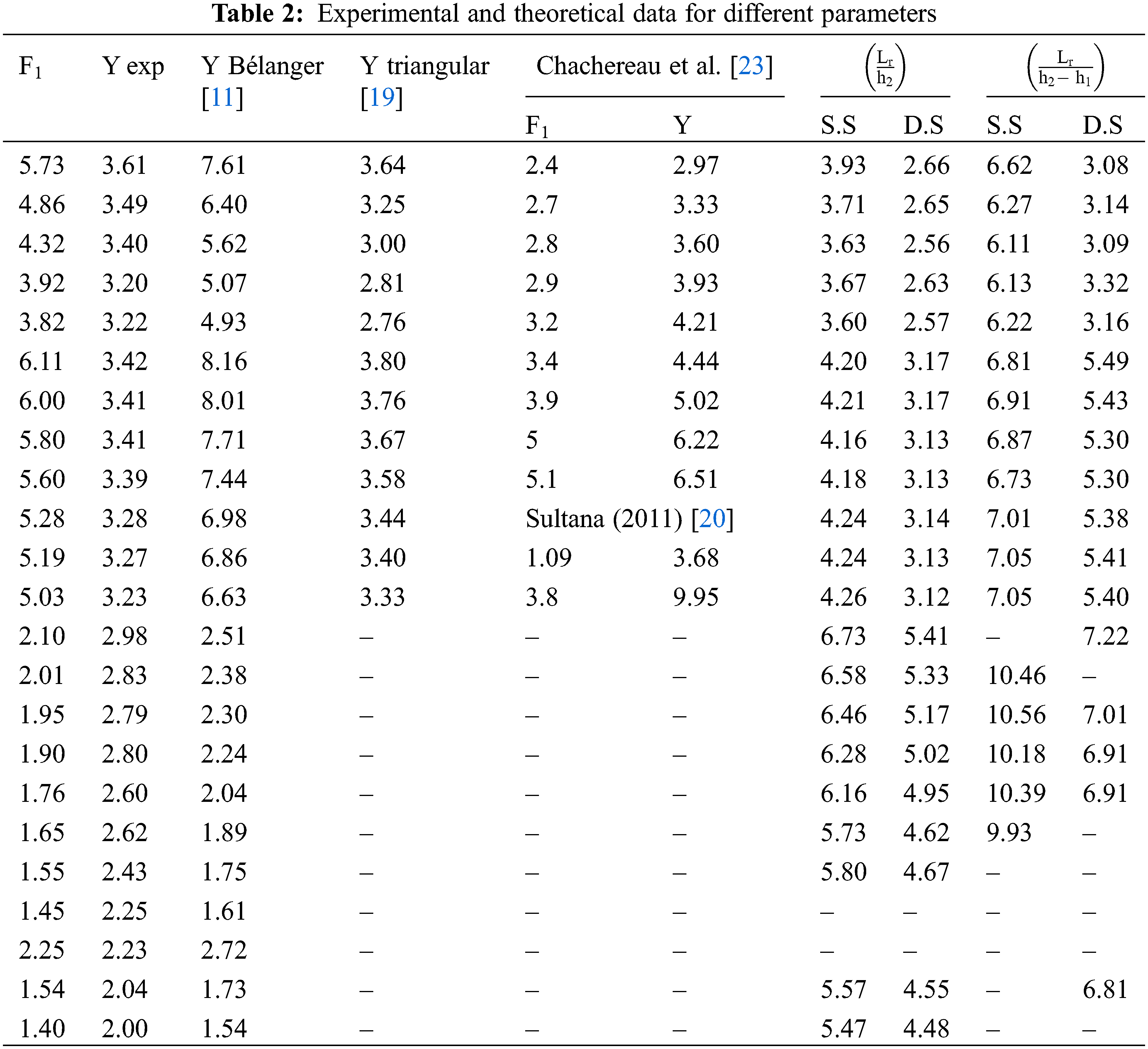
The experimental and theoretical data for different parameters are shown in Table 2.
The efficiency of a hydraulic jump for an asymmetrical trapezoidal channel is given by Eq. (3) [4], when:
With A1
With h2d > D: A2
Using the general relationship of the efficiency is given by [4]:
The efficiency Eq. (19) can be written for an asymmetrical trapezoidal channel:
When: D = 0, it is the case of a rectangular channel:
Wanoschek et al. gave the same relation for a rectangular channel Eq. (24), which verifies the asymmetric trapezoidal channel relations Eqs. (16) and (17) [16].
Comparing Eqs. (20) and (22) with Eq. (3), we find that Eqs. (20) and (22) have not been verified for our channel type, for 3.82 < F1< 6.11, which is due to the non-horizontality of the free surface upstream of the hydraulic jump. Therefore, it is necessary to verify these relationships for a horizontal upstream free surface.
For this reason, we propose a relationship based on the graph η = f(F1) Eq. (25), with
For a hydraulic jump in a triangular channel with a 90° opening angle, with a slope angle between the walls (m = 0.03), b = 0.5 m and 3.61 < F1< 12.98, we used the results of Debabeche et al. [19], the efficiency is calculated by the following relationship:
For a symmetrical trapezoidal channel with a slope angle between the walls (m = 1.62), b = 0.2 and 2.40 < F1 < 12.80, we used the results of Wanoschek et al. [16], the efficiency is calculated by the following relationship:
Fig. 13 shows the efficiency values η in triangular, symmetrical trapezoidal, and asymmetrical trapezoidal channels.
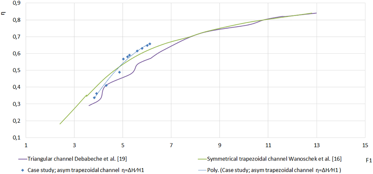
Figure 13: Efficiency η of the hydraulic jump as a function of inflow Froude number for three channels: Triangular, symmetric trapezoidal, and asymmetric trapezoidal
For the range 3.82 < F1 < 4.86, the efficiency of the hydraulic jump is between that of the triangular and trapezoidal symmetrical channels. The efficiency of the hydraulic jump in an asymmetric trapezoidal channel is higher than its homologs in a triangular and symmetrical trapezoidal channel for the range 5.02 < F < 6.11.
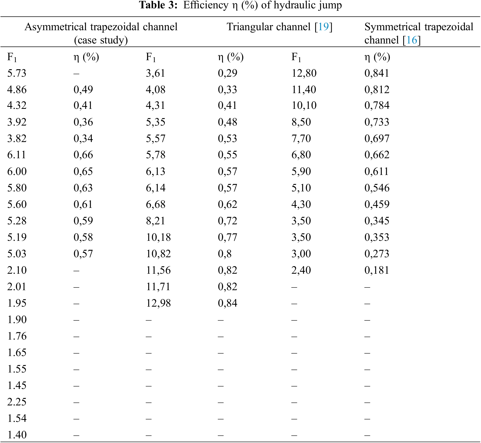
The efficiency of hydraulic jump for the different channels are shown in Table 3.
This study investigated the properties of a hydraulic jump in an asymmetric trapezoidal channel under various upstream inflow conditions of 1.40 < F1 < 6.11. The primary hydraulic jump parameters were investigated, such as sequent depth and characteristic length. The goal of studying these parameters was to size the hydraulic structures and reinforce the zones subjected to high erosion forces. The experimental results for the subsequent depth and characteristic length revealed that the variation of Y, Lr/h2 and Lr/h2-h1 ratios increases with the inflow Froude number. Furthermore, the results showed that, in contrast to the asymmetrical trapezoidal channel shape with a triangular gate, the asymmetrical trapezoidal channel shape with parallelogram gates reduced more hydraulic jump height and length than the rectangular channel. As a result, the asymmetrical trapezoidal channel with parallelogram gates was shorter than the triangular channel.
Moreover, the findings highlighted some novel information about the efficiency of a hydraulic jump in an asymmetric trapezoidal channel, and a new relation was developed for the efficiency for 3.82 < F1 < 6.11. Our case study was compared to other types of channels regarding efficiency. For 3.82 < F1< 4.86, the efficiency of the hydraulic jump was between the triangular and trapezoidal symmetrical channels and was considered more effective than the triangular and symmetric trapezoidal channel for 5.02 < F1< 6.11. The results can be used to calculate the size of energy dissipation basins. The results presented in this paper are only valid for the transverse bottom slope and channel width used in this study. This study, which focused on the hydraulic jump on a specific channel shape (asymmetrical trapezoidal), paves the way for future research into other asymmetrical trapezoidal cross-sectional geometries, such as different transverse bottom slopes and channel widths.
Acknowledgement: The authors express their gratitude to the LARGHYDE Laboratory at Biskra University and the HECE Laboratory at Liege University for their support in conducting this research.
Funding Statement: The authors received no specific funding for this study.
Author Contributions: This work represents an experimental study of a hydraulic jump in an asymmetrical trapezoidal channel with different sluice gates. The experimental tests were carried out with great precision, the analysis and comparison of the results with the literature were carried out over several steps. The authors confirm contribution to the paper as follows: Bouthaina Debabeche: study conception and design; data collection, analysis and interpretation of results and draft manuscript preparation. Sonia Cherhabil: conception and design. All authors reviewed the results and approved the final version of the manuscript.
Availability of Data and Materials: The data used in the study are shown in Tables 1–3.
Conflicts of Interest: The authors declare that they have no conflicts of interest to report regarding the present study.
References
1. Nakayama Y. Introduction to fluid mechanics. 2nd edOxford: Butterworth-Heinemann; 2018. [Google Scholar]
2. Gupta SK, Mehta RC, Dwivedi VK. Modeling of relative length and relative energy loss of free hydraulic jump in horizontal prismatic channel. Procedia Eng. 2013;51:529–37. [Google Scholar]
3. Chanson H. Hydraulics of aerated flows: qui pro quo? J Hydraul Res. 2013;51(3):223–43. [Google Scholar]
4. Sinniger RO, Hager WH. Hydraulic constructions-stasional flows. 2nd edLausane: Editions Presses Polytechniques Romandes; 1989. p. 435–8 (In French). [Google Scholar]
5. Macián-Pérez JF, Bayón A, García-Bartual R, López-Jiménez PA, Vallés-Morán FJ. Characterization of structural properties in high reynolds hydraulic jump based on CFD and physical modeling approaches. J Hydraul Eng. 2020;146(12):04020079. [Google Scholar]
6. Anandraj A. Investigational study on self aeration characteristic of hydraulic jump. J Mech Civ Eng. 2012;4(2):27–31. doi:https://doi.org/10.9790/1684-0422731. [Google Scholar] [CrossRef]
7. Edmar Schulz H, Dorn Nóbrega J, Andrade Simões AL, Schulz H, de Melo Porto R. Details of hydraulic jumps for design criteria of hydraulic structures. In: Edmar Schulz H, editor. Hydrodynamics-concepts and experiments. Rijeka: InTech; 2015. p. 73–116. [Google Scholar]
8. Hager WH. Energy dissipators and hydraulic jump. 1st edLondon: Springer Science + Business Media; 1992. [Google Scholar]
9. Kim HS, Choi S, Park M, Ryu Y. Flow turbulence and pressure fluctuations in a hydraulic jump. Sustainability. 2023;15:14246. doi:https://doi.org/10.3390/su151914246. [Google Scholar] [CrossRef]
10. Macián-Pérez JF, García-Bartual R, García-Bartual R, López-Jiménez PA, Vallés-Morán FJ. Numerical modeling of hydraulic jumps at negative steps to improve energy dissipation in stilling basins. Appl Water Sci. 2023;13:203. doi:https://doi.org/10.1007/s13201-023-01985-4. [Google Scholar] [CrossRef]
11. Chanson H. Momentum considerations in hydraulic jumps and bores. J Irrig Drain Eng. 2012;138(4):382–5. doi:https://doi.org/10.1061/(asce)ir.1943-4774.0000409. [Google Scholar] [CrossRef]
12. Bakhmeteff BA, Matzke M. The hydraulic jump in terms of dynamic similarity. Trans Am Soc Civ Eng. 1936;101(1):360–47. doi:https://doi.org/10.1061/taceat.0004708. [Google Scholar] [CrossRef]
13. Hager WH, Bremen R, Kawagoshi N. Classical hydraulic jump: length of roller. J Hydraul Res. 1990;28(5):591–608. doi:https://doi.org/10.1080/00221689009499048. [Google Scholar] [CrossRef]
14. Jesudhas V, Balachandar R, Wang H, Murzyn F. Modelling hydraulic jumps: IDDES versus experiments. Environ Fluid Mech. 2020;20:393–413. [Google Scholar]
15. Bahmanpouri F, Gualtieri C, Chanson H. Flow patterns and free-surface dynamics in hydraulic jump on pebbled rough bed. Proc Inst Civ Eng Water Manage. 2023;176(1):32–49. doi:https://doi.org/10.1680/jwama.20.00040. [Google Scholar] [CrossRef]
16. Wanoschek R, Hager WH. Hydraulic jump in trapezoidal channel. J Hydraul Res. 1989;27(3):429–46. [Google Scholar]
17. Rodriguez-Diaz AJ. The hydraulic jump in a non-rectangular open channel (Ph.D. Thesis). University of Georgia: USA; 1954. [Google Scholar]
18. Hager WH, Wanoschek R. Hydraulic jump in triangular channel. J Hydraul Res. 1987;25(5):549–64. doi:https://doi.org/10.1080/00221688709499255. [Google Scholar] [CrossRef]
19. Debabeche M, Cherhabil S, Hafnaoui A, Achour B. Hydraulic jump in a sloped triangular channel. Can J Civ Eng. 2009;36(4):655–8. [Google Scholar]
20. Roushangar K, Ghasempour R. Evaluation of the impact of channel geometry and rough elements arrangement in hydraulic jump energy dissipation via SVM. J Hydroinf. 2019;21(1):92–103. doi:https://doi.org/10.2166/hydro.2018.028. [Google Scholar] [CrossRef]
21. Kiri U, Leng X, Chanson H. Positive surge propagating in an asymmetrical canal. J Hydro-Environ Res. 2020;31:41–7. doi:https://doi.org/10.1016/j.jher.2020.04.002. [Google Scholar] [CrossRef]
22. Atashi V, Lim YH, Khajavi M, Shafai-Bajestan M. Characteristics of hydraulic jumps in stilling basins with permeable six-legged elements. In: World Environmental and Water Resources Congress, 2020; Reston, USA. [cited 2020 May 14]; p. 66–75. doi:https://doi.org/10.1061/9780784482971.007. [Google Scholar] [CrossRef]
23. Chachereau Y, Chanson H. Free-surface fluctuations and turbulence in hydraulic jumps. Exp Therm Fluid Sci. 2011;35(6):896–909. doi:https://doi.org/10.1016/j.expthermflusci.2011.01.009. [Google Scholar] [CrossRef]
24. Afzal N, Bushra A. Structure of the turbulent hydraulic jump in a trapezoidal channel. J Hydraul Res. 2002;40(2):205–14. doi:https://doi.org/10.1080/00221680209499863. [Google Scholar] [CrossRef]
Cite This Article
 Copyright © 2024 The Author(s). Published by Tech Science Press.
This work is licensed under a Creative Commons Attribution 4.0 International License , which permits unrestricted use, distribution, and reproduction in any medium, provided the original work is properly cited.
 Downloads
 Citation Tools