
 Submit a Paper
 Propose a Special lssue
 Open Access
ARTICLE

Heat Transfer Enhancement of the Absorber Tube in a Parabolic Trough Solar Collector through the Insertion of Novel Cylindrical Turbulators
1 Department of Electrical Techniques, Al-Mussaib Technical Institute, Al-Furat Al-Awsat Technical University, Babil, Iraq
2 Department of Physics, Collage of Science, University of Kerbala, Karbala, Iraq
3 Department of Energy Engineering, Collage of Engineering/Al-Musayab, University of Babylon, Babil, Iraq
* Corresponding Author: Yasser Jebbar. Email:
Fluid Dynamics & Materials Processing 2024, 20(6), 1279-1297. https://doi.org/10.32604/fdmp.2024.050753
Received 16 February 2024; Accepted 30 April 2024; Issue published 27 June 2024
 View Full Text
 Download PDF
Abstract
This study includes an experimental and numerical analysis of the performances of a parabolic trough collector (PTC) with and without cylindrical turbulators. The PTC is designed with dimensions of 2.00 m in length and 1.00 m in width. The related reflector is made of lined sheets of aluminum, and the tubes are made of stainless steel used for the absorption of heat. They have an outer diameter of 0.051 m and a wall thickness of 0.002 m. Water, used as a heat transfer fluid (HTF), flows through the absorber tube at a mass flow rate of 0.7 kg/s. The dimensions of cylindrical turbulators are 0.04 m in length and 0.047 m in diameter. Simulations are performed using the ANSYS Fluent 2020 R2 software. The PTC performance is evaluated by comparing the experimental and numerical outcomes, namely, the outlet temperature, useful heat, and thermal efficiency for a modified tube (MT) (tube with novel cylindrical turbulators) and a plain tube (PT) (tube without novel cylindrical turbulators). According to the results, the experimental outlet temperatures recorded 63.2°C and 50.5°C for the MT and PT, respectively. The heat gain reaches 1137.5 W in the MT and 685.8 W in the PT. Compared to the PT collector, the PTC exhibited a (1.64 times) higher efficiency.Keywords
Nomenclature
| Aa | Area of reflector (m2) |
| AL | The altitude of location above mean sea level (km) |
| a0 | Constant |
| a1 | Constant |
| cp | Specific heat capacity of fluid (J/Kg.°C) |
| DS−E | The mean distance between the sun and earth (m) |
| do | Outer diameter of the tube (m) |
| fL | Focal length of receiver tube (m) |
| I0 | Extraterrestrial solar radiation (W/m2) |
| Ib | Beam radiation (W/m2) |
| ISC | Solar constant (W/m2) |
| k | Constant |
| L | Length of parabola (m) |
| Larc | Arc length of the aperture (m) |
| | Mass flow rate (kg/s) |
| N | Number of day |
| P | Pressure (Pa) |
| Qinc | Incident solar radiation (W) |
| Quse | Useful heat (W) |
| Tfi | Inlet fluid temperature (K) |
| Tfo | Outlet fluid temperature (K) |
| v | Velocity of fluid (m/s) |
| Wa | Diameter of aperture (m) |
| Greek Symbols | |
| µ | Viscosity of fluid (kg/m.s) |
| ρ | Density of fluid (kg/m3) |
| ηth | Thermal efficiency (%) |
| θr | Rim angle (degree) |
| θz | Zenith angle (degree) |
One of the renewable energy sources is solar energy, which is used in two processes: the optical process and the thermal process, depending on the application used. The parabolic trough collector (PTC) is used in the thermal process, as it converts solar energy reflected from its reflector into thermal energy absorbed from the absorbing tube that transfers thermal energy to the heat transfer fluid (HTF). The reflector of the PTC is often made of aluminum panels, which are characterized by good reflectivity and a light weight for the purpose of bending them precisely. The parabolic trough collector tube (PTCT) is usually made of stainless steel, which is characterized by its lack of chemical interaction with the HTF and the air of the environment surrounding it.
To improve a base fluid’s thermal conductivity, such as thermal oil or water, nanoparticles with sizes of a few nanometers are dispersed inside the fluid [1]. It has been discovered that these fluids produce positive outcomes with improved PTC performance. However, there are several issues associated with using nanofluids, including their high cost and stability issues brought on by agglomeration [2]. Therefore, their current use in commercial applications is well-established.
However, another method that makes use of flow inserts in the PTCT or different geometric alterations in the inner absorber region is the use of turbulators. The objective is to generate passive vortexes to increase the flow’s rate of mixing [3]. The improved heat transfer rate and increased PTC performance are the end results. There are no significant restrictions on the application of these strategies in the real system. One drawback is that the amount of pumping effort increases, which is also the case with the nanofluids.
In order to enhance the PTC’s performance, various ways have been presented and investigated by researchers. Reddy et al. [4] did an experimental investigation into the development of the thermal performance of a PTCT using a porous disc. They found these discs enhanced the daily thermal efficiency to record in the range of 63.9%–66.7%. Kaood et al. [5] presented a new way to improve the thermal-hydraulic efficiency of PTCT using a conical absorber. The results showed that a conical absorber enhances the heat transfer rate up to 65%. The use of helical coils had been studied by Okour et al. [6] and Chakraborty et al. [7]. The first group found that the thermal efficiency of a PTC by using these turbulators reached up to 64.7%, whereas the second group found that the maximal increase in useful thermal energy output for tubes with these turbulators is 32.37%. Some researchers had explored a lot of information about improving the hydrothermal performance of a PTCT using twisted tape. Jaramillo et al. [8] and Stanek et al. [9] studied effected twisted ratios; they observed that thermal efficiency increased as the twisted ratio decreased. Isravel et al. [10] explained the influences of rings attached to twisted tape; the modified inserts showed an increase in thermal efficiency of 24% compared with the plain tube compared with a PT case. In addition, Singh et al. [11] used conical strip inserts with malty pitch ratios, and they found there was a significant enhancement in Nusselt number (
From the literature survey, it can be concluded that there is a lack of data on the performance of cylindrical turbulators inserted in the PTCs. In this work, the contribution of the cylindrical turbulators inside the absorber tube of the PTC is experimentally and numerically investigated. The geometry of the parabolic reflector section used solar flux of high reflectivity applied over the 2 m long stainless steel in the reflector rigid surface, 1 m aperture width, and 90° of rim angle, which results in focusing all incident solar radiation into the focal line and a heat collection element (stainless steel tube) through which HTF flows. The tube is placed on the focal line of the collector, which is also parallel to its axis of rotation.
Experimentally, there was no device available to measure the beam solar radiation falling on the PTC system at the work location, so the radiation values were calculated theoretically. Solar radiation is a constant and simultaneous flow of energy outward from the sun in all directions. Solar radiation can be divided into two types: extraterrestrial solar radiation (ESR) and terrestrial solar radiation (TSR). The ESR represents the solar radiation outside the earth’s atmosphere. The ESR depends on many factors, such as the distance and orientation of the work location; it varies by the inverse square law, as shown in the following equation [6,19]:
The distance between the sun and earth changes with the earth’s orbital position around the sun, so it is related to the days of the year. Usually, the ESR is calculated from the following empirical equation [19,20]:
The TSR represents the amount of solar radiation that actually reaches the earth’s surface. The total radiation incident on a surface (at the earth’s surface) is comprised of two forms: the first is beam radiation (Ib), and the second is diffuse radiation (Id). The reflection of the PTC receives the beam radiation, so we focused on calculating its value. The beam radiation is given by the following equation [6,19]:
where:
To calculate the altitude of any location (AL), we can use a GPS device (which equals to 0.033 km for college of Engineering/Al-Mussaib).
2.2 Thermal Performance of the PTC
The useful heat of the absorber tube of PTC is obtained by the HTF when its flow between the inlet and outlet of the absorber and it can be calculated from [9,13,21]:
The total incident solar radiation can be obtained from [9,21]:
The area of aperture is given as [19]:
Finally, the thermal efficiency of a PTC can be defined as the ratio of heat useful by the absorber tube, to the total incident solar radiation. The thermal efficiency can be calculated using the following equation [13,17,21]:
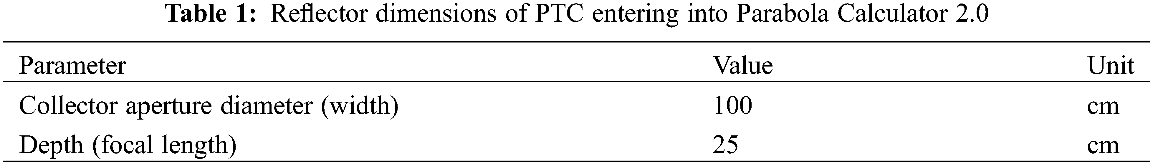
A simulation study was performed on the absorber tube with and without cylindrical turbulators using the ANSYS Fluent 2020 R2 software. A parabolic arc was drawn using Parabola Calculator 2.0 (as shown in Fig. 1) according to the following equation [17,18]:

Figure 1: The dimensions of reflector of the PTC in the parabola calculator
The focal length that is assumed has value of 25 cm in this study. Therefore, the parabola curve function in this case is expressed as:
Table 1 lists the dimensions of the reflector of PTC that were entered into the Parabola Calculator 2.0 in order to draw this reflector as shown in the Fig. 1.
The arc length can be estimated based on the rim angle and the focal length using (see Fig. 2) [22]:
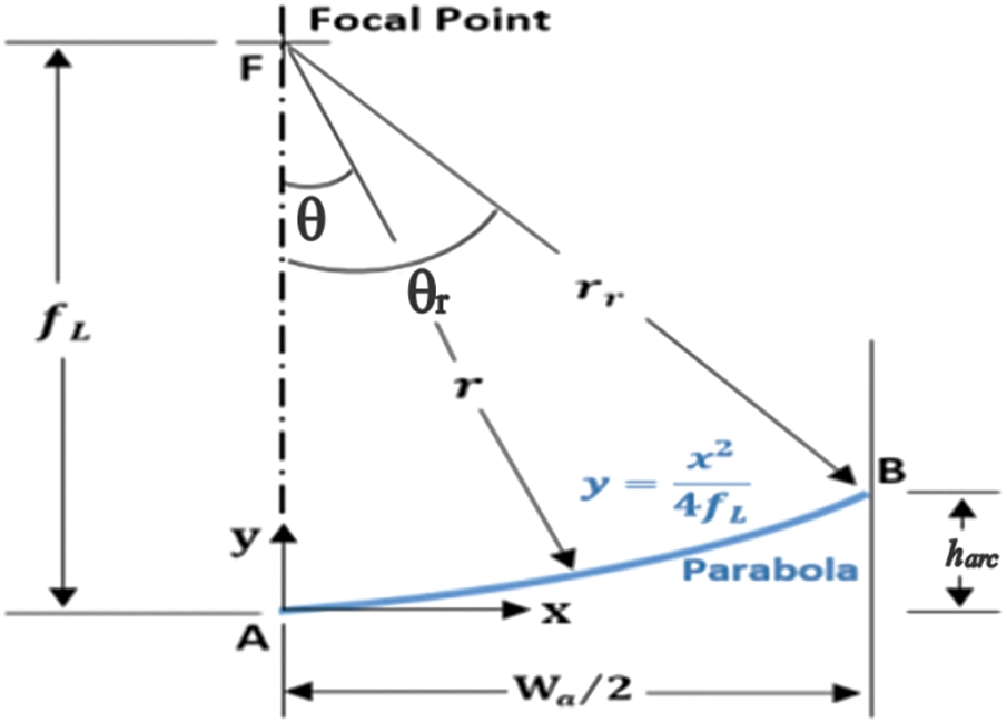
Figure 2: Basic design parameters of PTC
In order to choose the best absorber tube design that heats water with a temperature exceeding 80°C, six models in three-dimensional were designed using ANSYS software according to the characteristics of the horizontal circle tube heat exchanger as stated in Table 2. Fig. 3 presents the image and detailed diagram of the geometry and cross section of the cylindrical turbulators in the CFD.
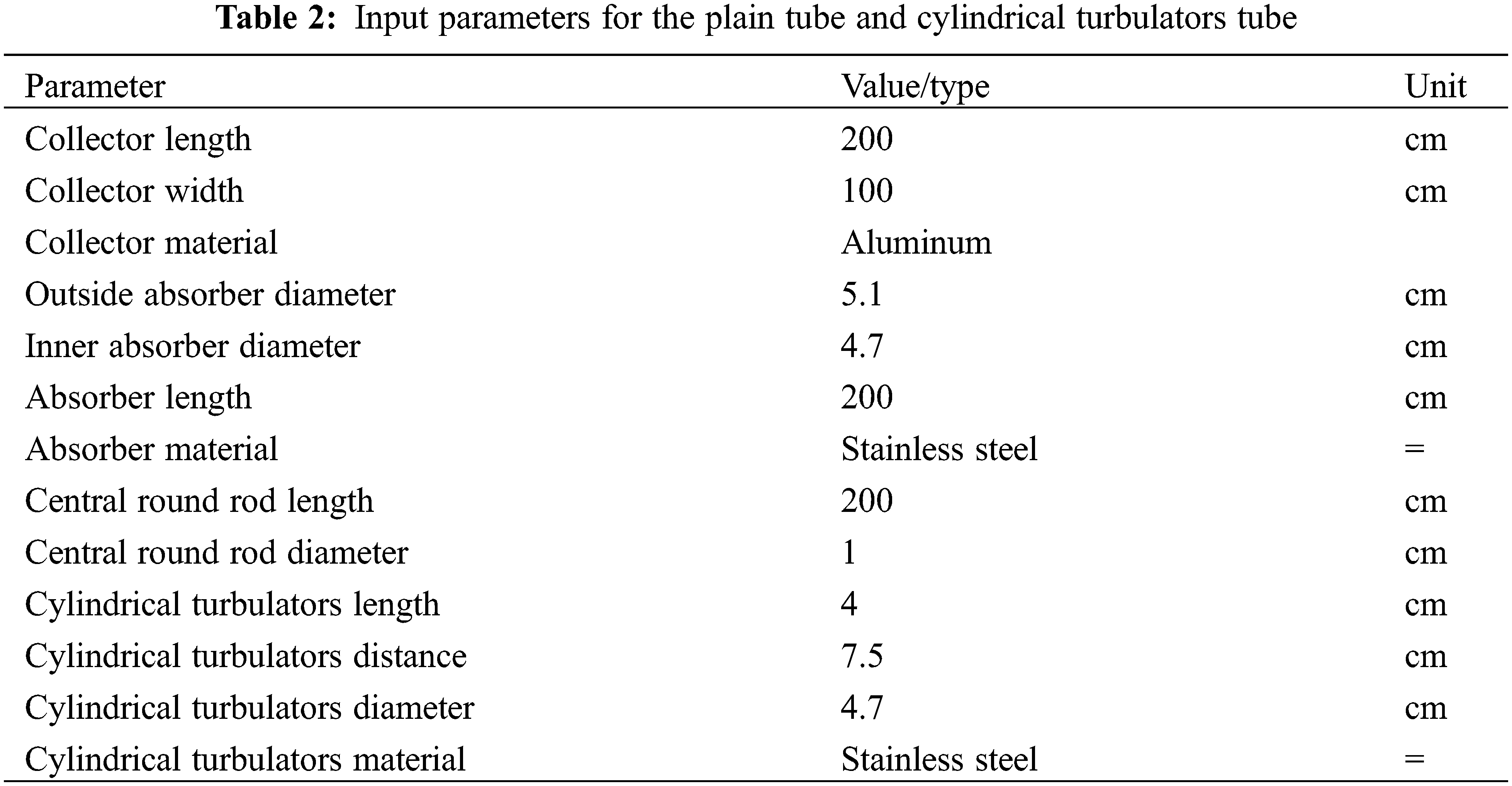
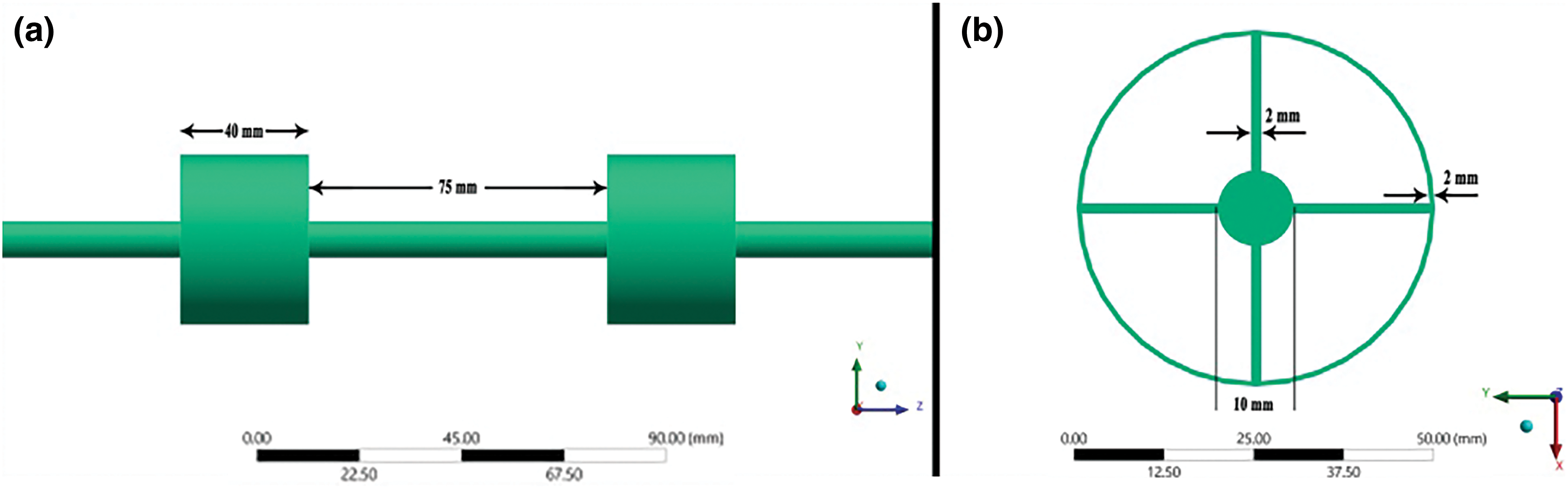
Figure 3: The CFD images of cylindrical turbulators tube (a) frontward view, and (b) cross section
The Navier-Stokes equations regulate the phenomena under investigation, and the k-ε realizable model is the suitable turbulence model, since it has been selected in several analogous investigations and was created by Patankar et al. [23].
The continuity:
The momentum:
The energy:
The boundary conditions of this model are listed below:
(1) The inlet water temperature is selected to be 300 K.
(2) The mass flow rate is selected to be 0.7 kg/s.
(3) The beam solar radiation is selected at 1000 W/m2.
CFD tools are also used to construct the computational mesh. To construct an appropriate mesh, several criteria, such as the number of starting cells and the amount of refinement in fluid, partial, and solid cells, are appropriately adjusted. A variety of meshes are evaluated, and Tables 3 and 4 provide a detailed report of the test findings. For both tubes (PT and cylindrical turbulators tube), five distinct mesh instances are looked at. In these scenarios, the input temperature was set at 300 K, and the mass flow rate was chosen at 0.7 kg/s. In both tubes, mesh 4 was chosen because it is clear that the output fluid temperature has converged in this mesh. The meshes for the PT (Fig. 4a) and cylindrical turbulators tube (Fig. 4b), measuring 40 mm in length, 2 mm in thickness, and 15 cylindrical turbulators, are evaluated.
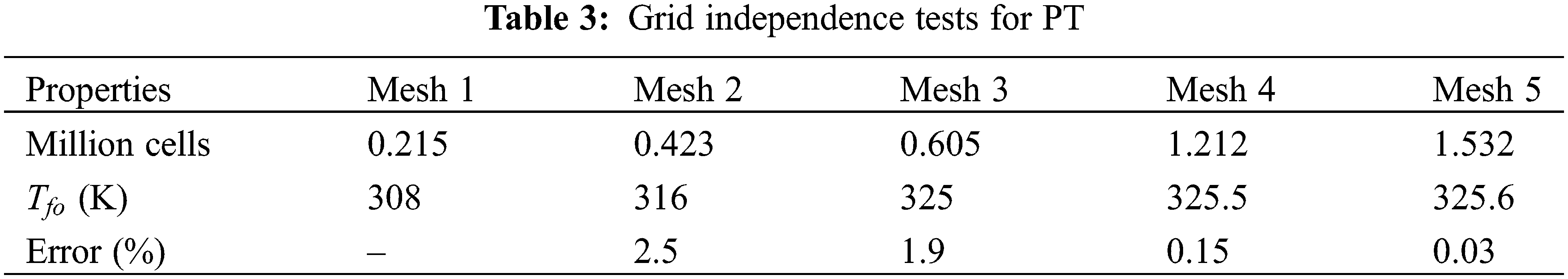
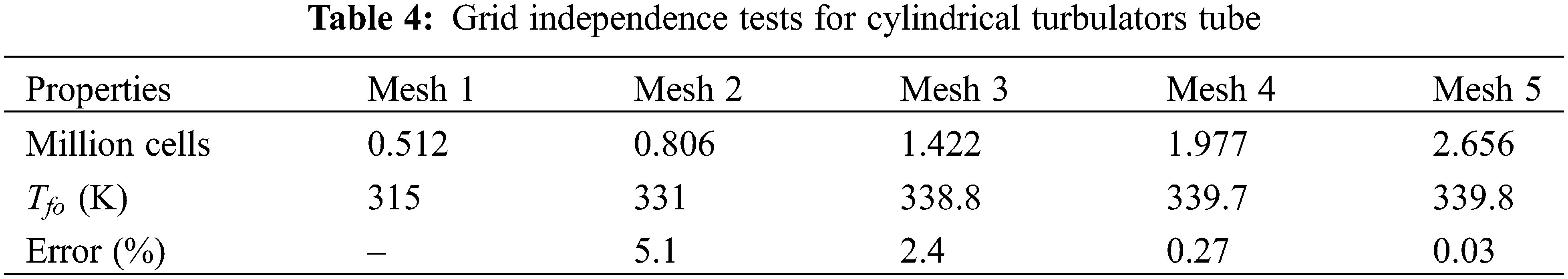
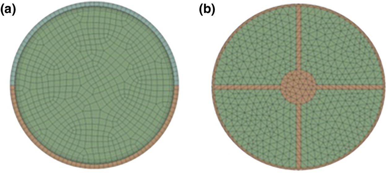
Figure 4: Mesh of: (a) PT, and (b) cylindrical turbulators tube
In this section, the accuracy of the developed model is presented through a validation test. More specifically, the model results of the present study are compared with the experimental correlations by Dittuse et al. [24]. The model results are examined for various Reynolds numbers by examining different mass flow rates from 0.6 to 1.0 kg/s, and the inlet temperature is 300 K.
According to Fig. 5, the results of the Nusselt number value of the PT showed a mean negative deviation of 2.6% from [24]. In addition, the minimum deviation is 0.1% at a mass flow rate of 0.7 kg/s, whereas the maximum deviation is 3.0% at a mass flow rate of 0.9 kg/s.
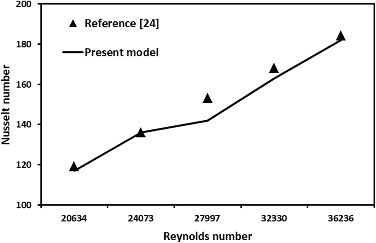
Figure 5: Nusselt number validation of this model
The next test is associated with the friction factor. The results of the presented model are compared with the results taken from [24], shown in Fig. 6.
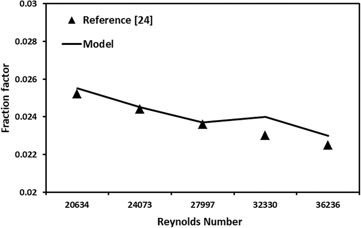
Figure 6: Fraction factor validation of this model
This test is for the PT, for various mass flow rates, and at a constant inlet temperature. The mean deviation between the results of this model and [24] is 1.5%. The minimum deviation is 0.4% at a mass flow rate of 0.7 kg/s, whereas the maximum deviation is 4.3% at a mass flow rate of 0.9 kg/s.
The observed variances were found to be negligible; suggesting that the data obtained from the plain tube exhibits a high level of dependability. Hence, the collected data may be used as a point of reference for assessing the performance of the tube when including the cylindrical turbulators.
The PTC model for the concentration of solar radiation has been fabricated to provide hot water, as shown in Fig. 7. The experimental setup used in this study consists of locally fabricated parts of one PTC with a total aperture area of 2.00 m2. The water gains heat gradually as it flows through the absorber tube in a sequential manner. In addition, the PTC is continuously oriented directly toward the beam radiation to achieve maximum efficiency. The PTC system mainly consists of a support structure, reflector, stainless steel absorber tube, and other accessories.
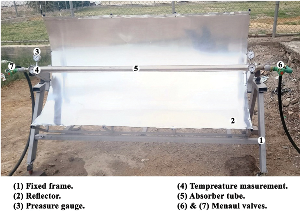
Figure 7: PTC structure with plate
The support structure for this model contains two main mechanical groups: stationary and moving bases. They represent a metal support frame and manual tracking for the model at the same time. The stationary structure of this model is made of a rectangular steel tube with a diameter of 6.35 cm, a length of 220 cm, and a width of 70 cm, welded together in the form of a movable pyramid frame by wheels welded from its lower end, as shown in Fig. 8.
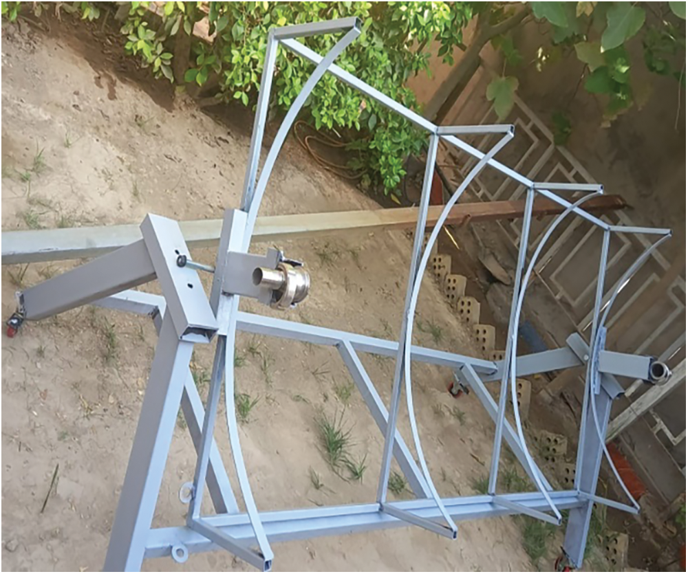
Figure 8: The supported structure of PTC
The moving structure of this model consists of two parts: the base and the reflector. The base is made from square steel pipes because it has maximum bending and shear stress. Square steel pipes have a diameter of 2.54 cm, a height of 25 cm, and a width of 100 cm. Aluminum sheets of size 100 cm × 200 cm with 1 mm thickness placed longitudinally on the PTC frame were used to form the reflector of the parabolic system because they are characterized by their light weight, resistance to weather conditions, ease of formation, and good reflectivity of solar radiation, as shown in Fig. 7. An aluminum sheet plate with a thickness of 1 mm was fixed with sixteen bolts over the structure of the PTC.
According to the dimensions obtained from Eqs. (12) and (13) with a rim angle of 90°, one rib model was fabricated as a template for the second piece. The rib width and depth calculated from these equations were 114.7 and 25 cm, respectively. Then, the two ribs are connected using five straight hollow square tubes with a length of 200 cm to form the PTC structure. In order to efficiently benefit from most of the solar reflected radiation, the sun rays must be highly concentrated on the absorber tube.
Several design factors are considered prior to the material selection of the absorber tube to be used. Several factors need to be taken into account, namely: the components of the absorber tube material must not react chemically with the water passing through it; the absorber tube material must withstand the external conditions surrounding the PTC system location; and the absorber tube material must withstand water temperatures that reach higher than 50°C. In addition, to ascertain the appropriate material and thickness for the tube, it is important to possess an understanding of the maximum pressure of the system. As a result, stainless steel was used in this experiment to effectively counteract chemical reactions, survive the effects of weathering, and maintain its structural integrity at high temperatures, as seen in Fig. 9. The selection of the size of the absorber tube was based on the parameters provided in Table 2.
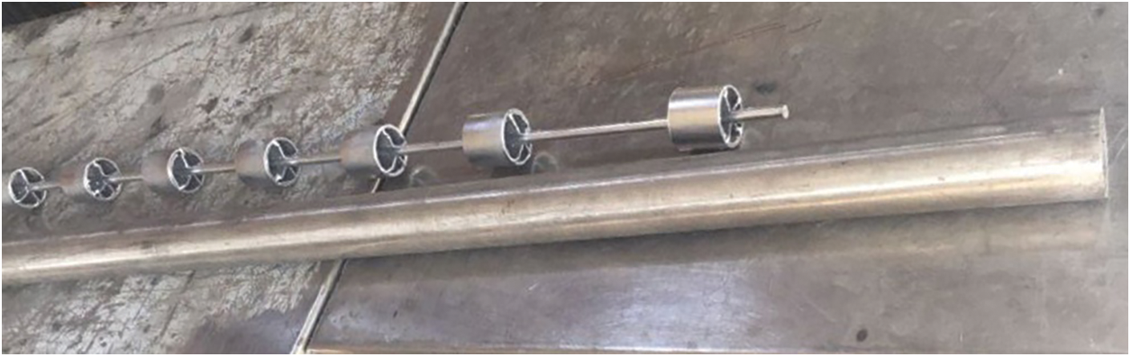
Figure 9: Photograph of the PT and cylindrical turbulators
The technical specifications for the cylindrical turbulators used in this study are given in Table 2. Fig. 10 shows the process of inserting the cylindrical turbulators inside the absorber tube.
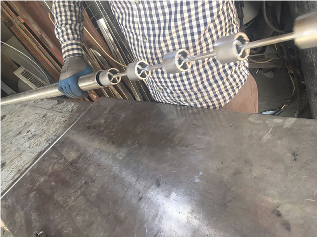
Figure 10: Cylindrical turbulators inside the absorber tube
6.1 The Number of Cylindrical Turbulators
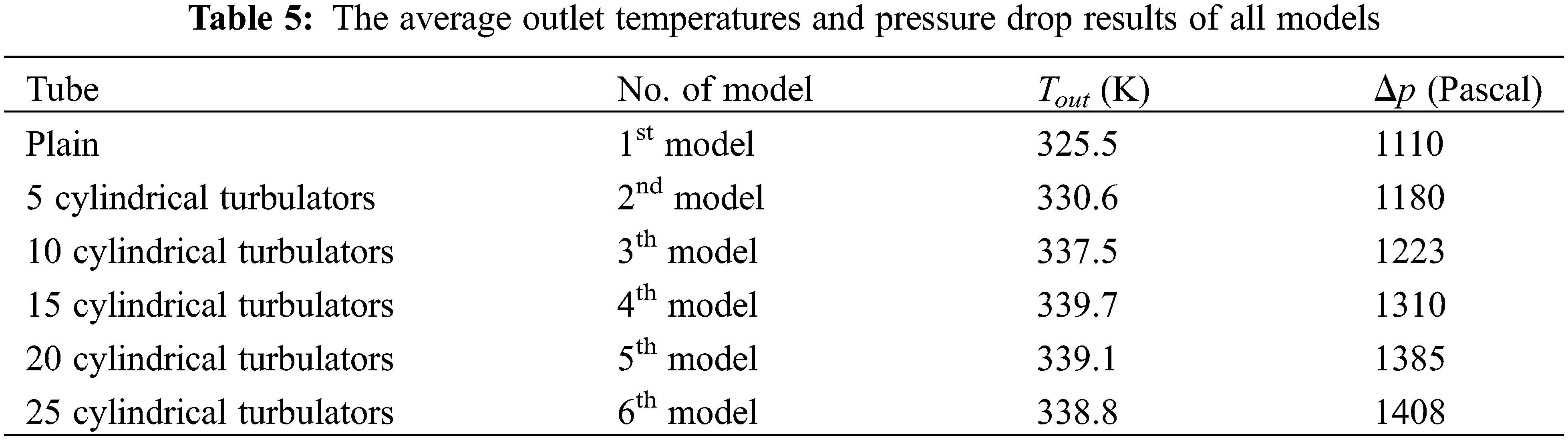
To determine the optimal number of cylindrical turbulators inside the absorber tube, six models are created using ANSYS Fluent. The first model is a tube without any turbulators (plain tube), and the rest are tubes with 5, 10, 15, 20, and 25 cylindrical turbulators, respectively. The cylindrical turbulators were connected to gather using a central rod in the models from second to sixth. All these models were simulated at an average inlet temperature of 300 K.
Table 5 lists the average outlet temperature of the water and the pressure drop inside the tube for each model. As the number of cylindrical turbulators increases by more than fifteen, the required solar energy to heat these turbulators will be greater than the required solar energy to heat the water; the heat loss by conduction will be greater than the heat gained by convection. On the other hand, it was observed that the pressure drop in the fifth and sixth models increases and the average outlet temperature of the water decreases. Based on these results, the number of cylindrical turbulators inside the absorber tube was selected to be fifteen cylindrical turbulators in the experimental part.
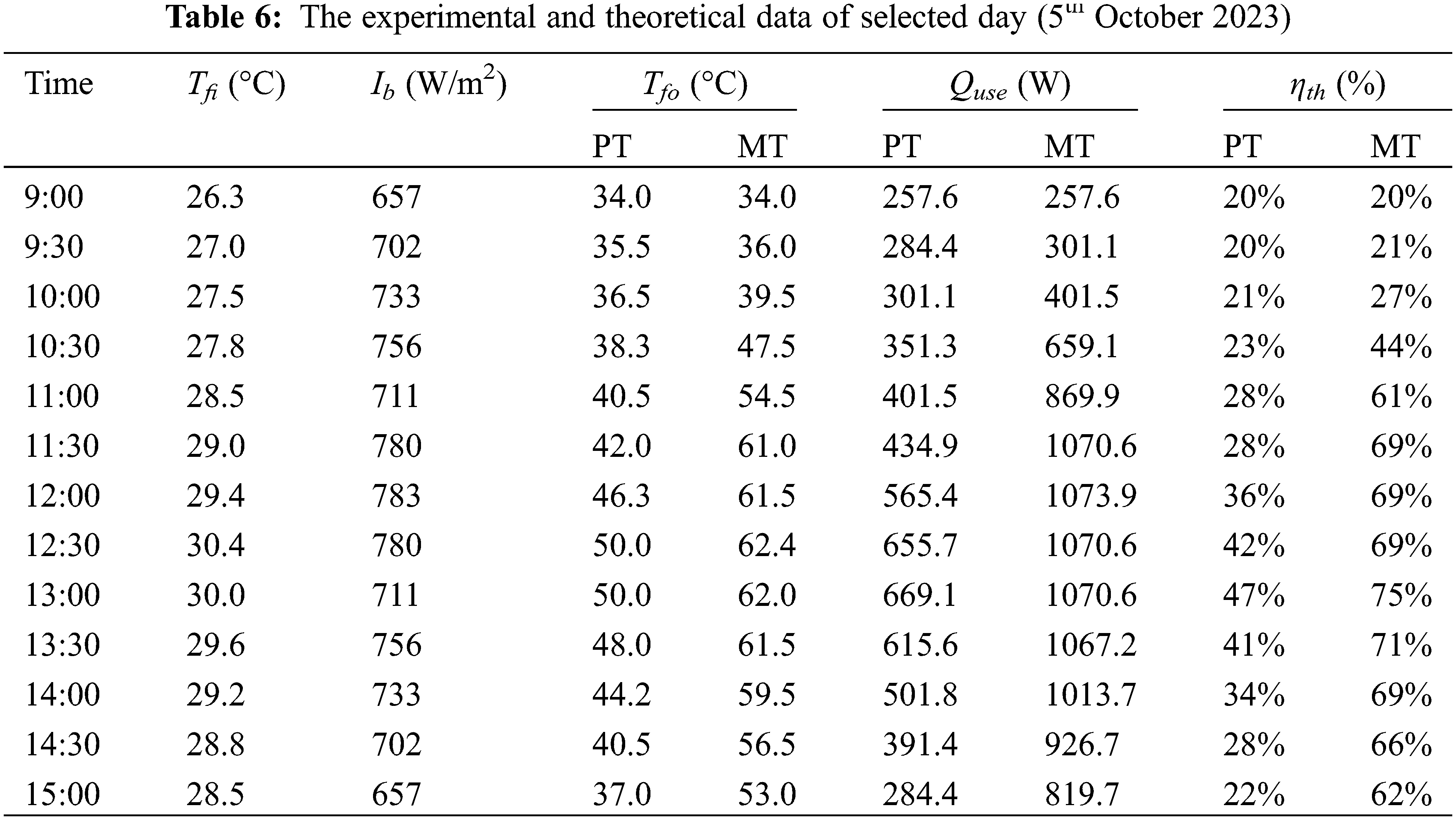
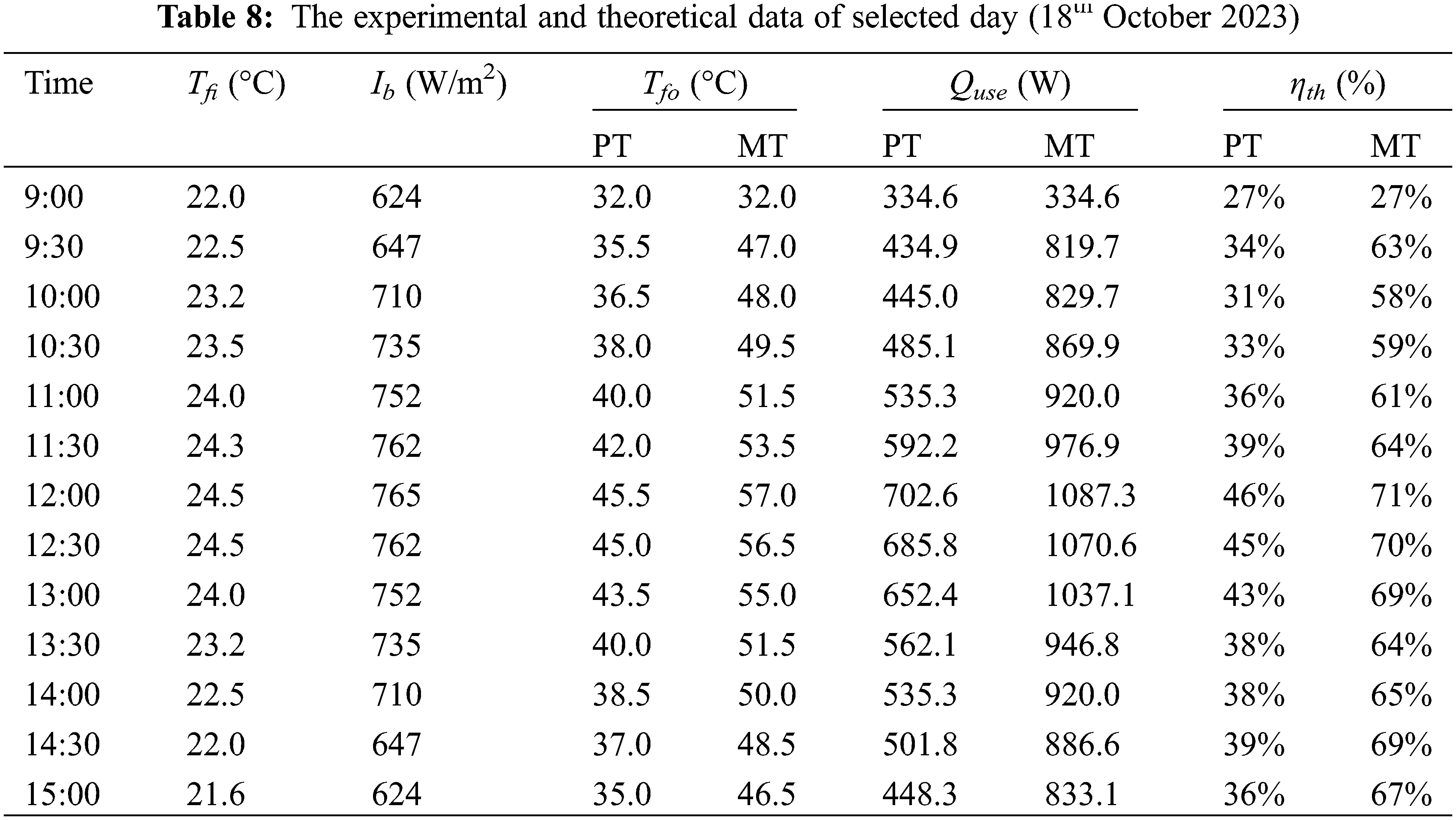
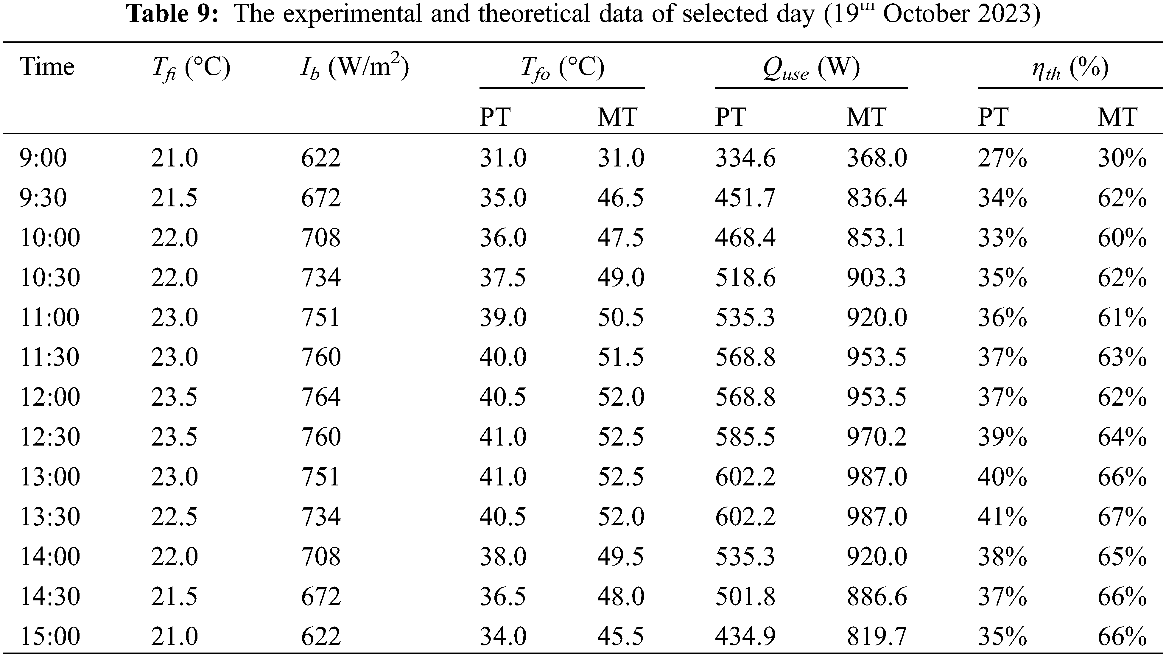
The results for four days of measurements on 5th, 12th, 18th, and 19th October 2023, at the College of Engineering/Al-Mussaib, Babil (32.77° N, 44.29° W), from 9:00 to 15:00 are presented in Tables 6–9. Setting and positioning the PTC manually according to sunlight and running the system for 60 min prior to recording the first reading. The time interval between each reading is set to 30 min. The temperatures of the water were measured at the inlet and outlet of the absorber tube using the temperature measurements. The data recording time lasted until 15:00 because, after this hour, the amount of the beam solar radiation drops.
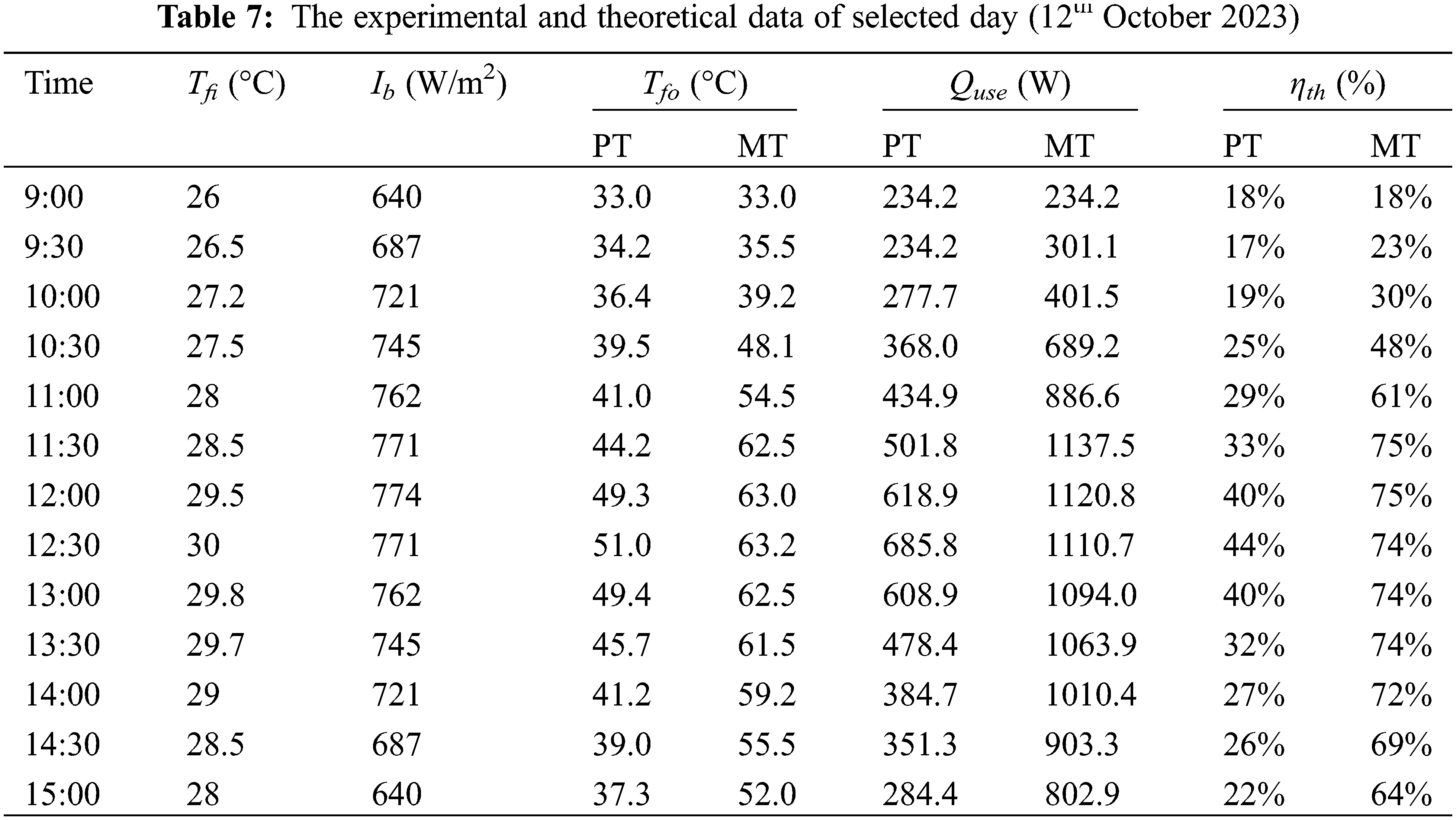
To solve the model, the measured data were taken experimentally for both cases: the plain tube (PT) and the modified tube (MT) (tube with fifteen cylindrical turbulators), along with the parameters and variables that were taken and applied to the model as inputs, including the inlet temperature, flow rate, absorber area, reflector area, weather date, and time. Then, the model determined the outlet temperature and useful heat. The modeled results are plotted for each case and compared with the experimental results on 12th October.
Fig. 11 shows the comparison between the experimental and numerical outlet temperatures of the water during the test day for the PT and MT.
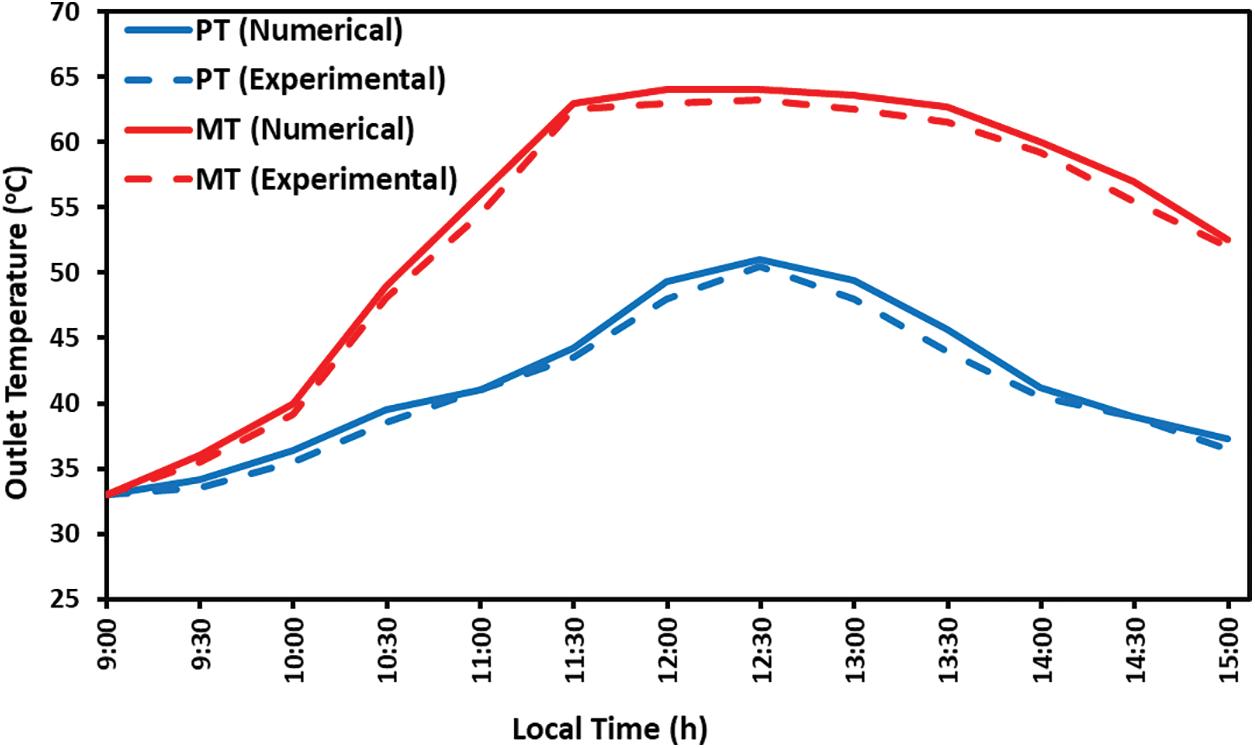
Figure 11: Comparison between the experimental and numerical outlet temperatures for the PT and MT
At 9:00, the outlet temperatures of the water recorded 33.0°C in all cases (numerical plain tube, experimental plain tube, numerical modified tube, and experimental modified tube) when the inlet water temperature was 26°C. Experimental results show that the outlet water temperatures for the PT case gradually rise until reaching 50.5°C at 12:30, then gradually drop to record 36.5°C at 15:00 due to decreasing the beam solar radiation. For the MT case, the experiments reveal that the outlet water temperature was recorded to be 34.5°C at 9:30, and then it suddenly rose to 62.5°C at 11:30 due to the presence of cylindrical turbulators. These turbulators enhance heat transfer exchange between the absorber tube surface and the thermal fluid by providing a higher surface area for heat transfer, generating a swirl flow, and increasing the residence time of the thermal fluid to gain more heat, but they also increase the pressure drop through the tube length. These advantages result in reaching higher temperatures in a short period of time, which in turn leads to an increase in the production of hot water that is useful in water desalination processes.
Furthermore, it was noted that the outlet water temperature begins to gradually decrease as a result of decreasing the beam solar radiation, but the drop in the outlet water temperature in the MT is relatively less than in the PT due to the cylindrical turbulators retaining the amount of heat gained during the daylight hours and gradually beginning to lose it to molecules of the water. In addition, the outlet water temperature in the MT has a higher value than in the PT, which enhances the heat transfer between the wall of the absorber tube and the water.
Numerically, the behavior of the two tubes (MT and PT) is similar to what was observed experimentally, but with higher values for the outlet water temperatures. Fig. 12 shows the agreement between the experimental and numerical results, where there are some discrepancies with a maximum error of 2.68% and 3.72% for the MT and PT, respectively.
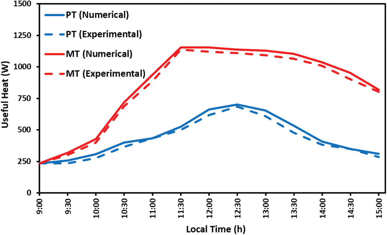
Figure 12: Comparison between the experimental and numerical useful heat for the MT and PT
The heat gain depends on the difference in the outlet and inlet temperatures of the water, according to Eq. (7). Therefore, the experimental useful heat begins to rise gradually to record its highest values of 1137.5 W when the temperature difference between the outlet and inlet water temperatures is 34.0°C in the MT and 685.8 W when the temperature difference is 20.5°C in the PT.
The useful heat in the MT case reaches its maximum value faster (at 11:30) than in the PT case (at 12:30). The values of useful heat in the MT remain within the high range for a longer period, unlike in the PT, where the values of useful heat are directly affected by the values of beam solar radiation. As in the outlet water temperature case (Fig. 11), the drop in the values of useful heat in the MT case is gradually less than in the PT case. All of these effects are attributed to the presence of cylindrical turbulators that retain heat, which begins to be lost after the values of the beam solar radiation drop. A convergence between numerical and practical results was observed with some contradictions, with a maximum error of 6.3% and 10.6% for the MT and PT cases, respectively.
Fig. 13 illustrates the experimental values of the thermal efficiency of the MT and PT with the daylight hours of the selected day. The thermal efficiency of the absorber tube gradually rose in the early hours of the selected day, reaching its highest value of 75% at 11:30 for the MT case and 44% at 12:30 for the PT case. Although the values of the beam solar radiation decrease after 12:30, the thermal efficiency remains within the high range of 75%–70% due to the presence of cylindrical turbulators that begin to lose their acquired heat to water molecules, in addition to the amount of the beam solar radiation. This feature shows the benefit of the presence of turbulators inside the absorber tube of the PTC’s system.
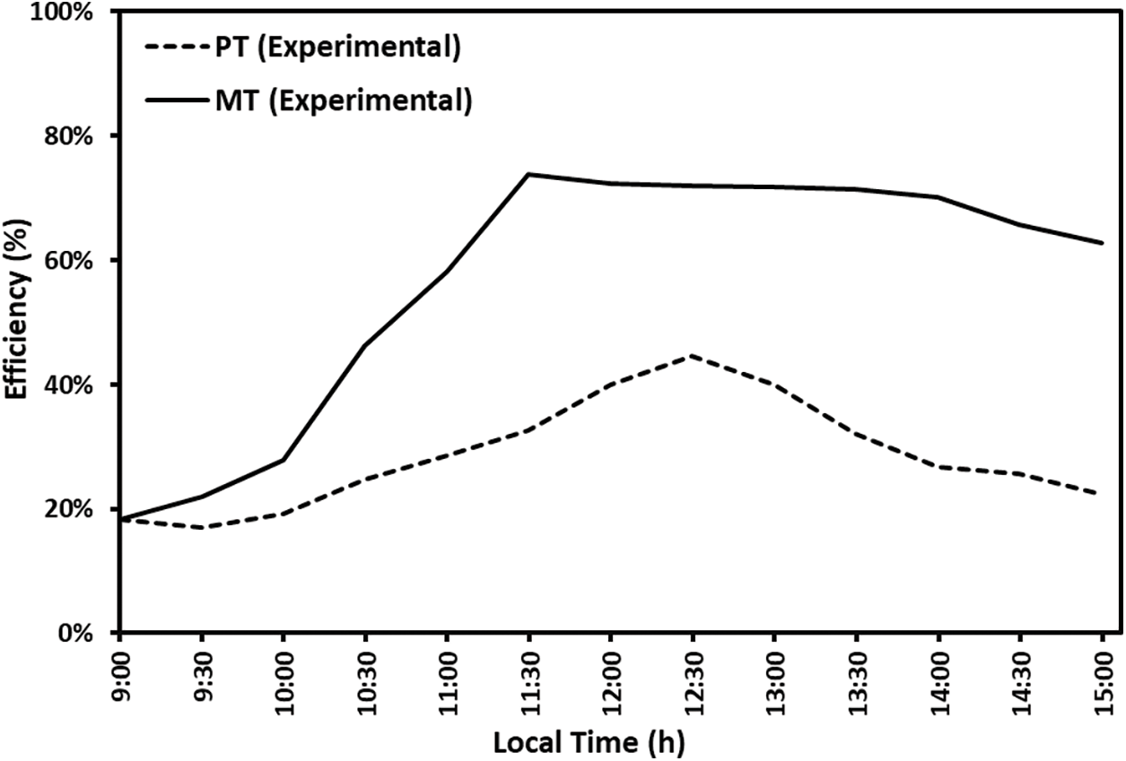
Figure 13: Experimental thermal efficiency and beam solar radiation during selected day for the MT and PT
Although the thermal efficiency is inversely proportional to the amount of solar radiation, as shown in Eq. (10), its values are observed to increase even after the amount of solar radiation decreases, especially in the afternoon. The reason is that the increase in the amount of useful heat is relatively large compared to the amount of solar radiation.
Generally, the comparison between experimental and numerical findings is acceptable, although there are some inconsistencies, and this is due to several reasons, including the fact that the theoretical calculations in the ANSYS are ideal in terms of weather conditions, which in fact change instantaneously and directly affect the values of water temperatures inside the tube and the accuracy of the thermo-measurements, manufacturing errors in the reflector of the PTC and the center of the focal point of the absorber tube, and errors in tracking the sun.
A comparison between the present work (cylindrical turbulators) and different types of inserts in terms of thermal efficiency ratio is provided in Table 10. The comparison shows that the proposed turbulator design has a positive effect on enhancing the thermal performance of the PTC.
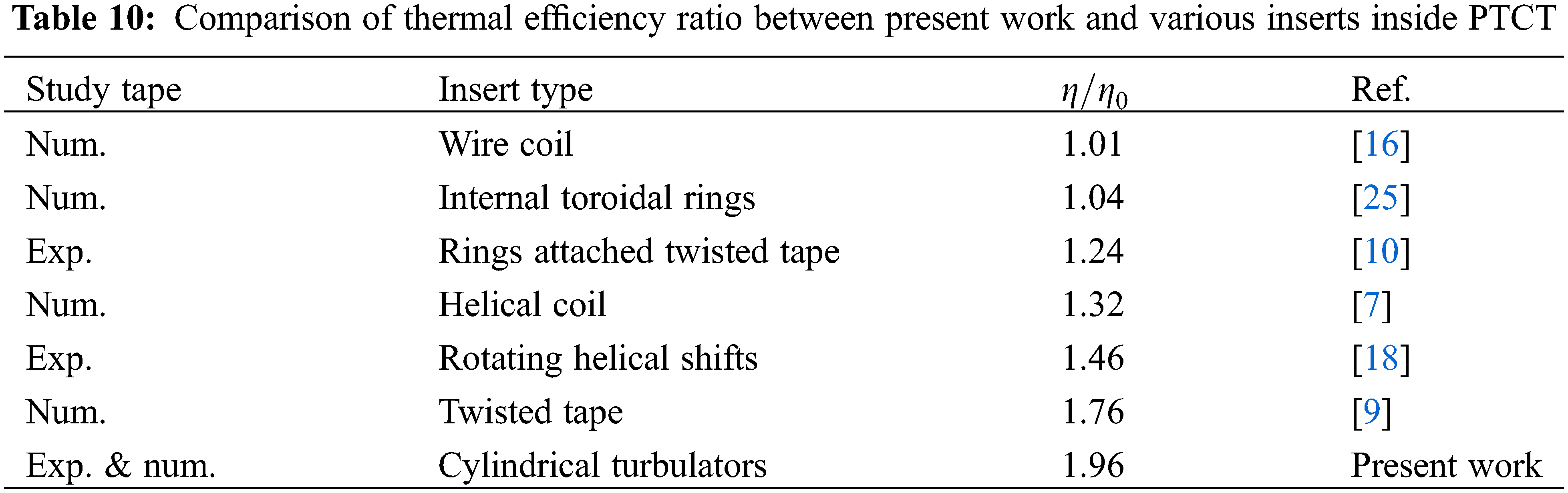
(1) Experimental and numerical results have shown that the maximum thermal efficiency of the PTC was recorded to be 75% for the PTC with cylindrical turbulators. The PTC with cylindrical turbulators exhibited higher efficiency than the PTC without cylindrical turbulators by 1.96 times.
(2) The PTC that has been performed is suitable for water desalination because of the high temperature of the outlet water, which exceeded 60°C.
(3) The outlet temperature, useful heat gain, and thermal efficiency in the absorber tube with cylindrical turbulators remain high even after the value of the beam solar radiation decreases.
(4) There is good agreement between experimental and numerical results, so it is worth performing a more in-depth investigation to enhance the performance of PTC, either by inserting new-designed turbulators or studying their effect on the PTC’s thermal performance.
Acknowledgement: None.
Funding Statement: The authors received no specific funding for this study.
Author Contributions: The authors confirm their contribution to the paper as follows: study conception and design: Yasser Jebbar, Fadhil Fluiful and Wisam Khudhayer; methodology: Yasser Jebbar; analysis and interpretation of results: Yasser Jebbar and Wisam Khudhayer; draft manuscript preparation: Yasser Jebbar. All authors reviewed the results and approved the final version of the manuscript.
Availability of Data and Materials: The data and materials that support the findings of this study are available on request from the corresponding author.
Conflicts of Interest: The authors declare that they have no conflicts of interest to report regarding the present study.
References
1. Kasaeian, A., Daneshazarian, R., Mahian, O., Kolsi, L., Chamkha, A. J. et al. (2017). Nanofluid flow and heat transfer in porous media: A review of the latest developments. International Journal of Heat and Mass Transfer, 107, 778–791. https://doi.org/10.1016/j.ijheatmasstransfer.2016.11.074 [Google Scholar] [CrossRef]
2. Gupta, M., Singh, V., Kumar, R., Said, Z. (2017). A review on thermophysical properties of nanofluids and heat transfer applications. Renewable and Sustainable Energy Reviews, 74, 638–670. https://doi.org/10.1016/j.rser.2017.02.073 [Google Scholar] [CrossRef]
3. Hafez, A., Attia, A., Eltwab, H., ElKousy, A., Afifi, A. et al. (2018). Design analysis of solar parabolic trough thermal collectors. Renewable and Sustainable Energy Reviews, 82, 1215–1260. https://doi.org/10.1016/j.rser.2017.09.010 [Google Scholar] [CrossRef]
4. Reddy, K., Kumar, K. R., Ajay, C. (2015). Experimental investigation of porous disc enhanced receiver for solar parabolic trough collector. Renewable Energy, 77, 308–319. https://doi.org/10.1016/j.renene.2014.12.016 [Google Scholar] [CrossRef]
5. Kaood, A., Ismail, O. A., Al-Tohamy, A. H. (2024). Hydrothermal performance assessment of a parabolic trough with proposed conical solar receiver. Renewable Energy, 222, 119939. https://doi.org/10.1016/j.renene.2024.119939 [Google Scholar] [CrossRef]
6. Okour, M., Al-Odat, M. Q. (2018). Experimental investigation of solar parabolic trough collector with a helical coil receiver under Jordan climate conditions. International Journal of Engineering &Technology, 7(4), 6415–6420. https://doi.org/10.14419/ijet.v7i4.20476 [Google Scholar] [CrossRef]
7. Chakraborty, O., Roy, S., Das, B., Gupta, R. (2023). Computational analyses of parabolic trough solar collector in the presence of helical coil-insert. International Journal of Environmental Science and Technology, 20(1), 683–702. https://doi.org/10.1007/s13762-021-03891-1 [Google Scholar] [CrossRef]
8. Jaramillo, O., Borunda, M., Velazquez-Lucho, K., Robles, M. (2016). Parabolic trough solar collector for low enthalpy processes: An analysis of the efficiency enhancement by using twisted tape inserts. Renewable Energy, 93, 125–141. https://doi.org/10.1016/j.renene.2016.02.046 [Google Scholar] [CrossRef]
9. Stanek, B., Ochmann, J., Węcel, D., Bartela, Ł. (2023). Study of twisted tape inserts segmental application in low-concentrated solar parabolic trough collectors. Energies, 16(9), 3716. https://doi.org/10.3390/en16093716 [Google Scholar] [CrossRef]
10. Isravel, R. S., Raja, M., Saravanan, S., Vijayan, V. (2020). Thermal augmentation in parabolic trough collector solar water heater using rings attached twisted tapes. Materials Today: Proceedings, 21, 127–129. https://doi.org/10.1016/j.matpr.2019.05.375 [Google Scholar] [CrossRef]
11. Singh, S., Samir, S., Kumar, K. (2024). Performance analysis of solar parabolic trough receiver with twisted perforated conical inserts. Proceedings of the Institution of Mechanical Engineers, Part E: Journal of Process Mechanical Engineering, 09544089231223001. https://doi.org/10.1177/09544089231223001 [Google Scholar] [CrossRef]
12. Venkatesaperumal, R., Syed Jafar, K. (2023). Performance of TiO2 nanofluids on the efficiency of a parabolic trough collector using a corrugated tube absorber with conical strip inserts. International Journal of Ambient Energy, 44(1), 1–13. https://doi.org/10.1080/01430750.2023.2190336 [Google Scholar] [CrossRef]
13. Bellos, E., Tzivanidis, C., Tsimpoukis, D. (2017). Multi-criteria evaluation of parabolic trough collector with internally finned absorbers. Applied Energy, 205, 540–561. https://doi.org/10.1016/j.apenergy.2017.07.141 [Google Scholar] [CrossRef]
14. Zaboli, M., Mousavi Ajarostaghi, S. S., Saedodin, S., Saffari Pour, M. (2021). Thermal performance enhancement using absorber tube with inner helical axial fins in a parabolic trough solar collector. Applied Sciences, 11(16), 7423. https://doi.org/10.3390/app11167423 [Google Scholar] [CrossRef]
15. Jafar Kutbudeen, S., Arulprakasajothi, M., Beemkumar, N., Elangovan, K. (2019). Effect of conical strip inserts in a parabolic trough solar collector under turbulent flow. Energy Sources, Part A: Recovery, Utilization, and Environmental Effects, 44(1), 2556–2568. https://doi.org/10.1080/15567036.2019.1650850 [Google Scholar] [CrossRef]
16. Yılmaz, İ.H., Mwesigye, A., Göksu, T. T. (2020). Enhancing the overall thermal performance of a large aperture parabolic trough solar collector using wire coil inserts. Sustainable Energy Technologies and Assessments, 39, 100696. https://doi.org/10.1016/j.seta.2020.100696 [Google Scholar] [CrossRef]
17. Abed, N., Afgan, I., Cioncolini, A., Iacovides, H., Nasser, A. (2022). Effect of various multiple strip inserts and nanofluids on the thermal-hydraulic performances of parabolic trough collectors. Applied Thermal Engineering, 201, 117798. https://doi.org/10.1016/j.applthermaleng.2021.117798 [Google Scholar] [CrossRef]
18. Allam, M., Tawfik, M., Bekheit, M., El-Negiry, E. (2022). Experimental investigation on performance enhancement of parabolic trough concentrator with helical rotating shaft insert. Sustainability, 14(22), 14667. https://doi.org/10.3390/su142214667 [Google Scholar] [CrossRef]
19. Duffie, J. A., Beckman, W. A., Blair, N. (2020). Solar engineering of thermal processes, photovoltaics and wind. New Jersey: John Wiley & Sons. [Google Scholar]
20. Mahdi, J. T., Jebbar, Y. A. (2019). A theoretical investigation of solar radiation and heat transfer in a solar pond in Karbala city. AIP Conference Proceedings, 2144(1), 030019. https://doi.org/10.1063/1.5123089 [Google Scholar] [CrossRef]
21. Bellos, E., Tzivanidis, C. (2018). Investigation of a star flow insert in a parabolic trough solar collector. Applied Energy, 224, 86–102. https://doi.org/10.1016/j.apenergy.2018.04.099 [Google Scholar] [CrossRef]
22. Abdulhamed, A. J., Rasheed, M. H., Kareem, H. K., Adam, N. M., Ab-Kadir, M. Z. A. et al. (2020). Design and performance testing of a parabolic trough collector including deformation test of the receiver tube. Journal of Advanced Research in Fluid Mechanics and Thermal Sciences, 67(2), 47–65. [Google Scholar]
23. Patankar, S. V., Spalding, D. B. (1972). A calculation procedure for heat, mass and momentum transfer in three-dimensional parabolic flows. International Journal of Heat and Mass Transfer, 15, 1787–1806. https://doi.org/10.1016/B978-0-08-030937-8.50013-1 [Google Scholar] [CrossRef]
24. Dittus, F., Boelter, L. (1985). Heat transfer in automobile radiators of the tubular type. International Communications in Heat and Mass Transfer, 12(1), 3–22. https://doi.org/10.1016/0735-1933(85)90003-X [Google Scholar] [CrossRef]
25. Ahmed, K. A., Natarajan, E. (2019). Thermal performance enhancement in a parabolic trough receiver tube with internal toroidal rings: A numerical investigation. Applied Thermal Engineering, 162, 114224. https://doi.org/10.1016/j.applthermaleng.2019.114224 [Google Scholar] [CrossRef]
Cite This Article
 Copyright © 2024 The Author(s). Published by Tech Science Press.
This work is licensed under a Creative Commons Attribution 4.0 International License , which permits unrestricted use, distribution, and reproduction in any medium, provided the original work is properly cited.
 Downloads
 Citation Tools