
 Submit a Paper
 Propose a Special lssue
 Open Access
ARTICLE

Transient Analysis of a Reactor Coolant Pump Rotor Seizure Nuclear Accident
1 Research Center of Fluid Machinery Engineering and Technology, Zhenjiang, 212013, China
2 School of Energy and Power Engineering, Jiangsu University, Zhenjiang, 212013, China
* Corresponding Author: Xiuli Wang. Email:
(This article belongs to the Special Issue: Multiphase Flow and Vortex Dynamics in Fluid Machinery)
Fluid Dynamics & Materials Processing 2024, 20(6), 1331-1349. https://doi.org/10.32604/fdmp.2023.046604
Received 08 October 2023; Accepted 14 November 2023; Issue published 27 June 2024
 View Full Text
 Download PDF
Abstract
The reactor coolant pump (RCP) rotor seizure accident is defined as a short-time seizure of the RCP rotor. This event typically leads to an abrupt flow decrease in the corresponding loop and an ensuing reactor and turbine trip. The significant reduction of core coolant flow while the reactor is being operated at full load can have very negative consequences. This potentially dangerous event is typically characterized by a complex transient behavior in terms of flow conditions and energy transformation, which need to be analyzed and understood. This study constructed transient flow and rotational speed mathematical models under various degrees of rotor seizure using the test data collected from a dedicated transient rotor seizure test system. Then, bidirectional fluid-solid coupling simulations were conducted to investigate the flow evolution mechanism. It is found that the influence of the impeller structure size and transient braking acceleration on the unsteady head (H) is dominant in rotor seizure accident events. Moreover, the present results also show that the rotational acceleration additional head (H) is much higher than the instantaneous head (H).Graphic Abstract
Keywords
Nomenclature
| Qr | Rated flow of the test pump |
| Hr | Rated head of the test pump |
| nr | Rated rotational speed of the test pump |
| T | Torque |
| Hu | Unsteady theoretical head |
| Hu1 | Rotational acceleration additional head |
| Hu2 | Instantaneous head |
There are three types of nuclear accident conditions classified during the operation of nuclear power plants [1,2]: Type I includes abnormal water supply, minor temperature imbalances, and slight reactor coolant flow loss, which are classified as medium-frequency accidents; Type II is classified as rare-frequency accidents, it includes small-break loss of coolant accidents and complete loss of coolant flow in forced circulation, among which the small-break loss involves small breaks of primary loop and secondary side system; Type III comprises reactor coolant pump (RCP) occurring rotor seizure or fracture, and a large-break loss of coolant accident in the primary coolant loop [3]. Type III accidents may be triggered by system or equipment failures due to uncontrollable natural disasters, such as severe earthquakes or tsunamis, so Type III accidents are severe accidents.
This paper mainly focuses on Type III rotor seizure accident, which occurs when RCP experiences sudden and significant resistance torque while operating at full load under its rated flow condition, leading to rotor seizure within a short time. The transient transition process of an RCP rotor seizure accident is crucial for assessing the operational safety of the nuclear power plant [4]. However, there is limited literature on rotor seizure accidents and related parameter changes. When the duration of rotor seizure is significantly shorter than that of coasting and emergency stop, the direct causes of the accident include coupling rupture of RCP, detachment of internal rotor components, and failures in the bearing lubrication system. After the start of the rotor seizure accident, the coolant flow rate in the primary loop system drastically decreases, which leads to abrupt changes in pressure and an increase in temperature. There is a potential risk of fuel rod departure from nucleate boiling (DNB) [5], which could result in dire consequences and pose significant threats to the safety of the nuclear power system and human living environment [6]. Therefore, it is essential to pay close attention to this issue.
Based on the safety demonstration, we mainly studied the transient hydraulic characteristics of the fluid-solid coupling under the RCP rotor seizure accident, a transition process from a specific pump condition to a reverse turbine condition accompanied by a very complex transient energy transformation. In practical engineering cases, absolute single-field problems are rare, as most physical phenomena exhibit coupled interactions. The fluid-solid coupling is a branch of mechanics that explores the coupling between the deformation of solids under fluid flow and the influence of solid deformation on the fluid field. It combines principles from fluid dynamics and vibration theories of elastic structures to simulate the coupling between fluids and solids [7]. When subjected to fluid loading, solid structures undergo displacement or deformation, affecting fluid loading and altering the overall distribution and magnitude of the fluid field. In order to simulate the interaction between fluid and solid, it is essential to select a suitable data transfer method for the coupling interface and coupling solution mode [8]. In recent years, research regarding RCP fluid-solid coupling has been as follows: To investigate the lubrication performance of tilting-pad thrust bearings during the startup process of nuclear pumps, Li et al. [9] developed a fluid dynamic lubrication model for tilting pad thrust bearings based on CFD method and fluid-solid coupling. Weng et al. [10] simulated the connection between the emergency cooling system of the new reactor CAP1400 and the pressure tank using the thermo-fluid-solid coupling method. They studied the flow, heat transfer, and structural deformation near the wall of the pressure vessel. Cuamatzi-Melendez et al. [11] developed a fluid-solid coupling method combining finite element and CFD to analyze the influence of water flow on the structural response of jet pump components and to predict the damage and failure of mechanical components of the nuclear power recirculation system.
This study constructs mathematical models for the transient flow rate and rotational speed during rotor seizure accidents based on rotor seizure tests. These models are utilized as boundary conditions in CFD simulations to investigate the internal flow characteristics within the pump during the transitional process of rotor seizure accidents. Specifically, the study analyzes the transient effects of unsteady heads and the variations in turbulent kinetic energy and vorticity within the impeller passage. These findings provide valuable insights for further analysis of the pump’s transient characteristics under rotor seizure conditions in reactor coolant systems.
The transient data acquisition of flow rate, rotational speed, and other hydraulic parameters was performed by rotor seizure tests of different severe degrees. These parameters’ temporal evolution laws and characteristics were analyzed during the rotor seizure process. Mathematical models describing the transient behavior of rotor seizure were established based on the collected data and used as boundary conditions for CFD flow-field analysis and transient analysis of fluid-solid coupling under rotor seizure conditions.
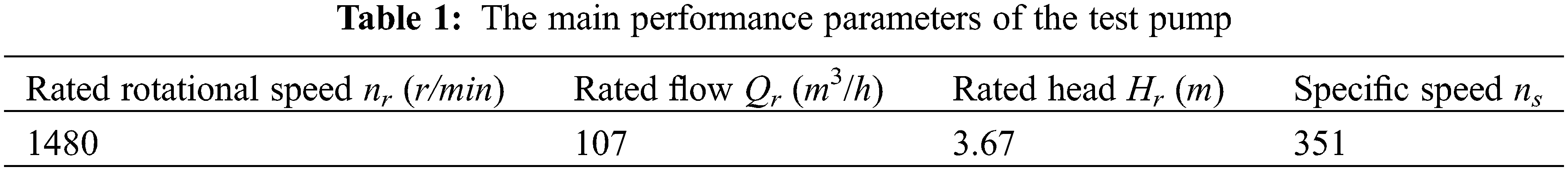
The transient rotor seizure test system consists of the test pump, a closed pipeline system, and a dynamic measurement system, as shown in Figs. 1 and 2. The main performance parameters of the test pump are shown in Table 1. The pressure fluctuations of monitoring points, rotational speed, torque, and flow rate of the test pump were measured during the transient transition process of different rotor seizure degrees. The steps and implementation process for conducting the transient rotor seizure tests are as follows:
1. Calibrated all data acquisition equipment, and the test pump was operated under rated flow conditions until it reached a steady state.
2. After the data acquisition system and the test pump stabilized for 5 s, the excitation current magnitude was adjusted by controlling the tension controller to obtain different torque values, resulting in different degrees of rotor seizure. At the same time, the motor power supply was disconnected.
3. The data acquisition system was used to acquire data at high speed for the flow rate Q, rotational speed n, torque T, and pressure fluctuations of monitoring points until the motor stopped rotating completely for 5~10 s. It was essential to recalibrate the data acquisition system before each test. The same excitation current was repeated three times, and three data sets were averaged for analysis.
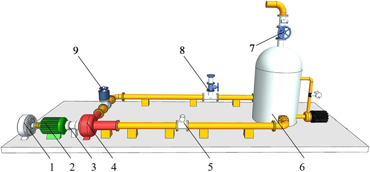
Figure 1: Schematic diagram of the transient rotor seizure test system (1. Magnetic powder brake; 2. Motor; 3. Torque sensor; 4. Test pump; 5. Turbine flow sensor; 6. Water tank; 7. Water tank exhaust valve; 8. Pipeline exhaust valve; 9. Export gate valve.)
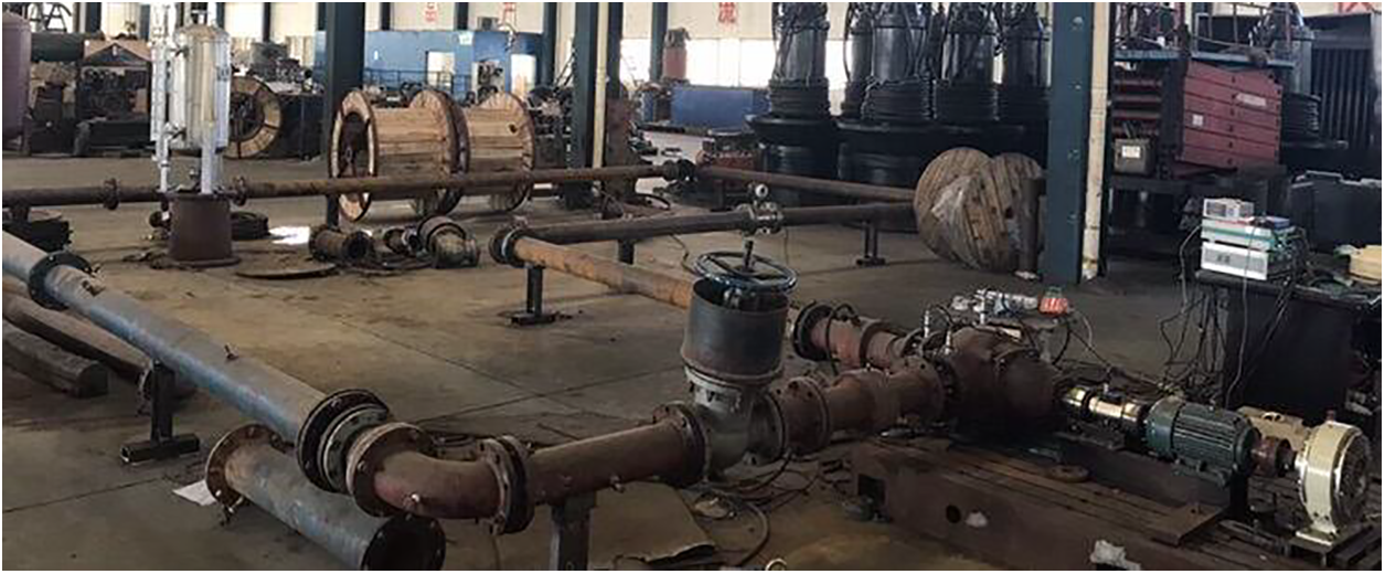
Figure 2: Site diagram of the transient rotor seizure test system
As shown in Table 2, this experiment was conducted with three sets of tests, with excitation currents of 0.14, 0.25, and 0.65 A, denoted as kz00, kz01, and kz02. According to the literature [6], it can be known that at the same time point, the test group with the more severe rotor seizure degree, its flow rate and rotational speed is lower, exhibiting a monotonic trend. Therefore, this study selected three test groups can represent slight, moderate, and severe degrees of rotor seizure.
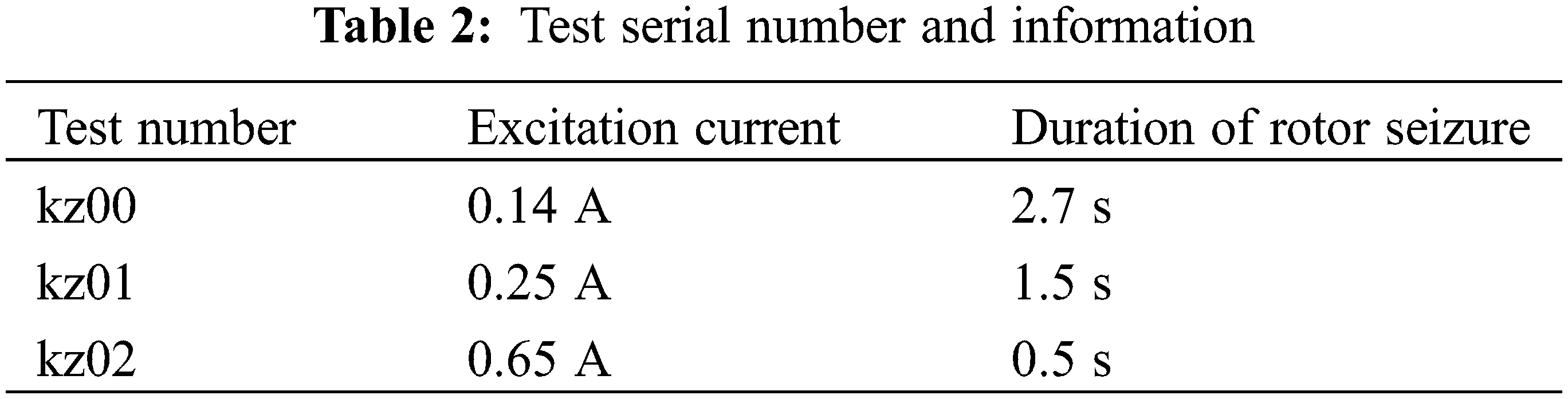
Fig. 3 depicts the transient flow rate and rotational speed variation curves for these three test groups. The portion before time point 0 s represents the stable operating state of the test pump, and time point 0 s marks the start of rotor seizure, after which the test pump enters the transient transition process. The flow rate curves approximately exhibit an exponential decline, while the rotational speed curves are nonlinear. Both of them approximately adhere to the relationship kz00 > kz01 > kz02, which matches the test results of the literature [6]. The severity of rotor seizure has a significant impact on rotational speed.
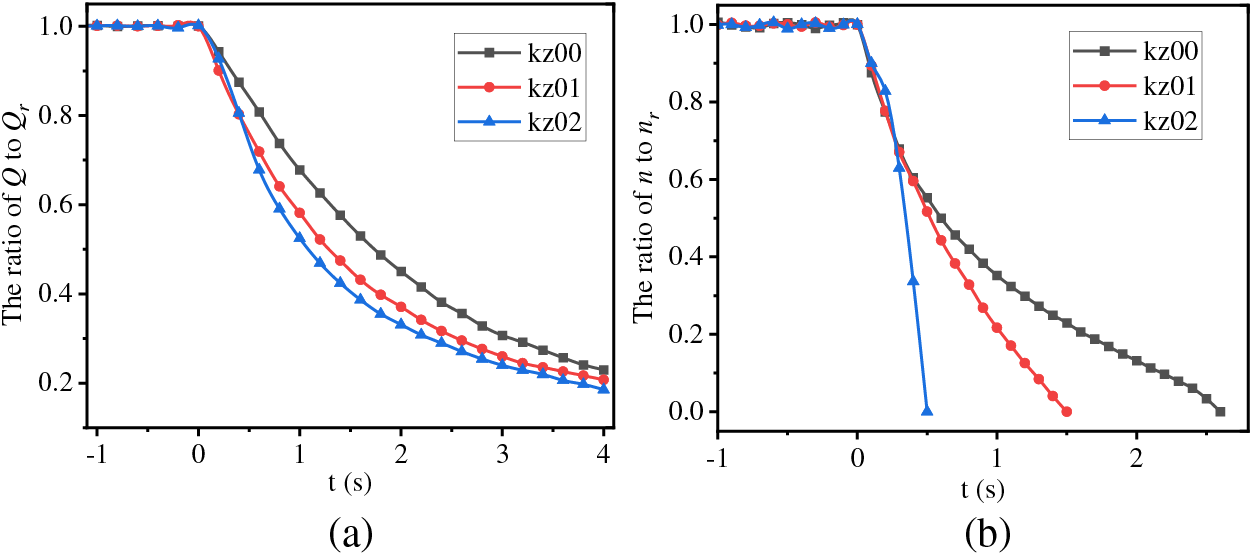
Figure 3: The transient (a) flow rate and (b) rotational speed change curves in the tests
2.3 Establishment of Mathematical Models
In order to further analyze the transient flow and coupled dynamic characteristics of the test pump at different rotor seizure degrees, MATLAB was employed to fit the flow rate and rotational speed variations of the three test groups. The corresponding mathematical model formulas were obtained and utilized as boundary conditions for CFD simulation. Since the flow state was stable before the start of the rotor seizure, the test pump was set to operate steadily at the rated operating condition for 0.1 s before the rotor seizure. The corresponding mathematical boundary models are as follows:
Case kz00:
Formula for flow Qt:
Formula of rotational speed nt:
Case kz01:
Formula for flow Qt:
Formula of rotational speed nt:
Case kz02:
Formula for flow Qt:
Formula of rotational speed nt:
The test pump in this study is a guide vane mixed-flow pump with a ring-shaped pump body. The coupling deformation of the test pump during simulations is small, while the structure of the test pump is complex, and strong flow turbulence occurred within the pump after the start of the rotor seizure accident. Therefore, to obtain more accurate simulation results, the bidirectional fluid-solid coupling method [12] was utilized to solve the fluid field and rotor structure field inside the RCP, and the solution process diagram is shown in Fig. 4. The bidirectional fluid-solid coupling simulation involves transient fluid field simulation in CFX and transient structure dynamics analysis in the transient structure module of ANSYS Workbench. For the smooth progress of the fluid-solid coupling simulation, solving the fluid field and the structure field, respectively, were required before solving the fluid-solid coupling simulation to ensure a good convergence.
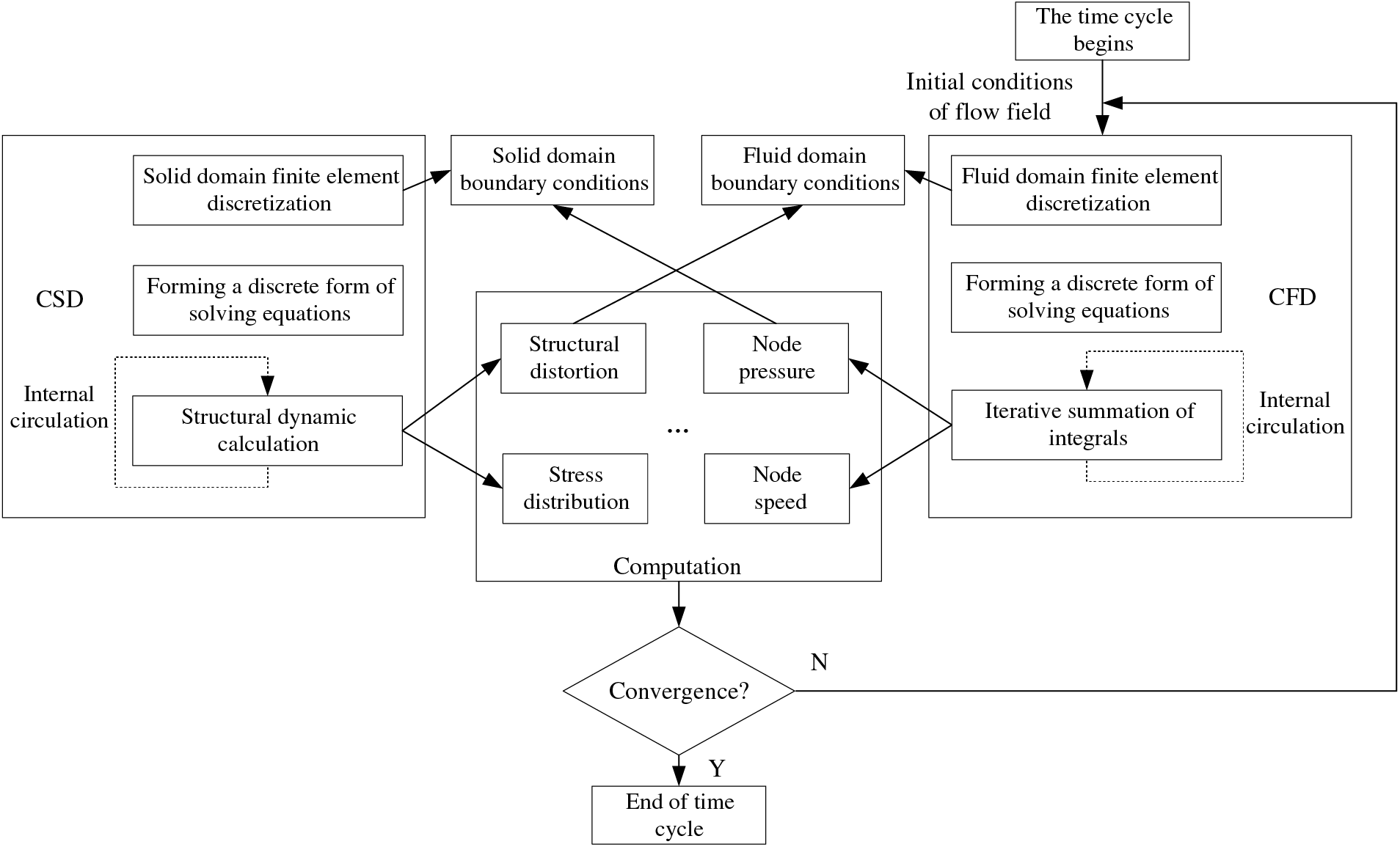
Figure 4: The bidirectional fluid-solid coupling solution process
For the fluid domain, calculations were performed using the Reynolds-averaged Navier-Stokes (RANS) equations and the Shear Stress Transfer (SST) turbulence model [13,14]. The RANS equations consist of the continuity equation Eq. (9) and the momentum equation Eq. (10).
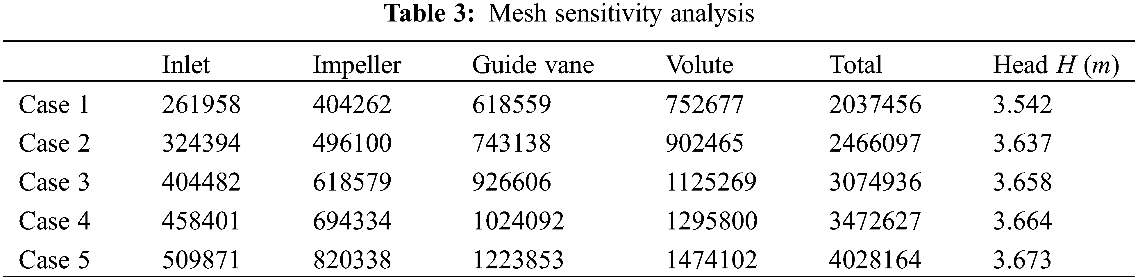
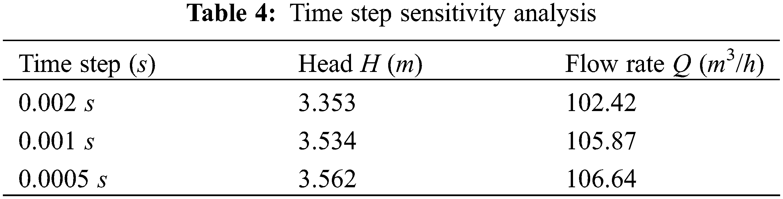
where ui and uj represent the velocity field in the i and j direction, m/s; p is the pressure term, Pa, which indicates the dynamic hydraulic pressure; g is the gravitational acceleration, m/s2; μ is the dynamic viscosity, Pa⋅s; t is time, s; and τij represents the Reynolds stress term, Pa; ρ is the density of the fluid, kg/m3. For transient analyses, the pressure-velocity coupling scheme was set as Coupled. The spatial discretization method was set as High Order Term Relaxation (HOTR), and the temporal discretization method was set as the second-order Euler backward difference format [15]. Considering the operating conditions of RCP, the inlet boundary condition was set as Total pressure, while the outlet was set as Mass flow. The reference pressure was 1 atm, and the wall roughness was 12.5 μm. The standard wall function was employed in the near-wall region, and the wall boundary condition was set as adiabatic no-slip. Dynamic mesh handling was implemented, and the residual convergence target for each simulation time step in the fluid field was set as 10−5. The meshing was performed using ICEM mesh partitioning software, as shown in Fig. 5. Hexahedral structured meshes were employed for all fluid domains. In order to balance computational resources, an analysis of sensitivity was conducted on the time step and mesh quantity in the simulations. Table 3 presents the mesh sensitivity analysis, where different cases with varying mesh quantities were simulated under the rated operating conditions with the same time step size. It can be observed that the variation in head obtained becomes less than 0.5% after the mesh quantity reaches 3 million. Hence, Case 3 was selected. Table 4 shows the time step sensitivity analysis, where different time step sizes were used in the simulations with the same mesh quantity under the rated operating condition. It can be seen that the variation in both flow rate and head between time step sizes of 0.001 and 0.0005 s is less than 1%. Therefore, a time step of 0.001 s was chosen for the simulations.
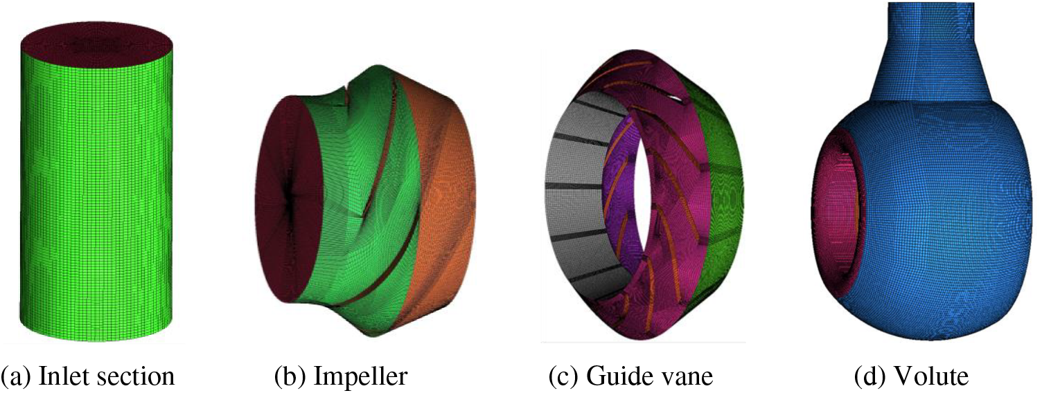
Figure 5: Fluid domain mesh of the overcurrent of reactor coolant pump model
For the solid domain, as shown in Fig. 6, the meshing of the impeller structure was carried out using the mesh module in ANSYS Workbench. To ensure that the impeller and the shaft have common nodes, the impeller and the shaft were first merged into a new combined body before mesh partitioning. According to the Hamilton’s principle, the structural dynamics equations of the elastic body can be expressed as follows [16]:
where M represents the mass matrix; C denotes the damping matrix; K represents the stiffness matrix; F represents the magnitude of the nodal forces, including centrifugal force load, gravity, and pressure; u denotes the nodal displacement vector;
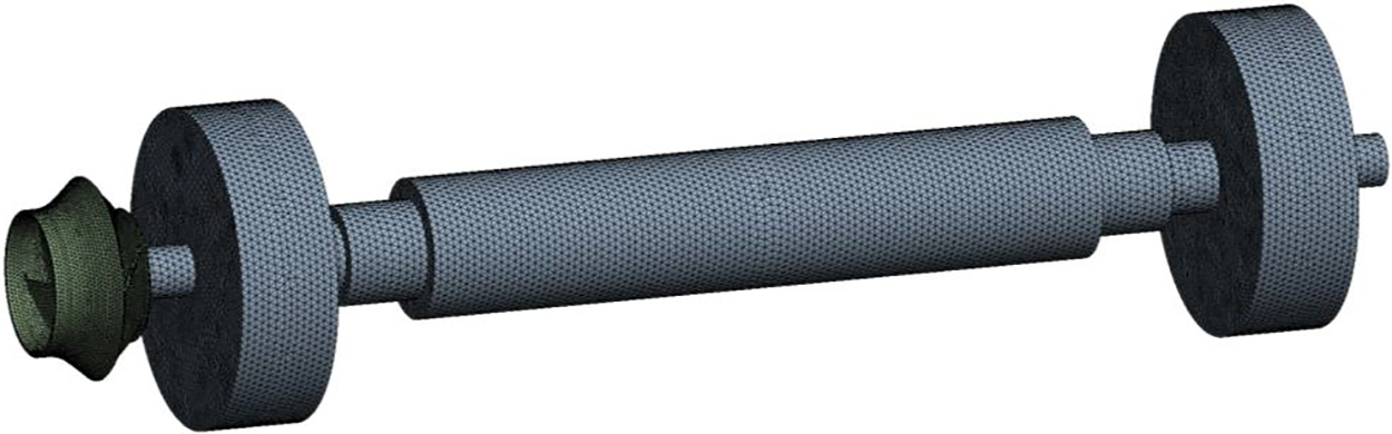
Figure 6: Solid domain mesh of the rotor of reactor coolant pump model
By utilizing CEL customize function functionality, formulas from MATLAB were inputted into CFX as the boundary conditions for flow rate and rotational speed. To ensure consistency between the transient fluid field simulation and the transient structure dynamic analysis in terms of time step and total time, the time step was set as 0.001 s, and the simulation total time for kz00, kz01 and kz02, were 2.8, 1.6 and 0.6 s. The results of bidirectional fluid-solid coupling in the steady-state condition of 1.0Q were taken as the initial condition. The joint solution of fluid-solid coupling was achieved using the arbitrary Lagrange-Euler (ALE) method [17].
2.5 Description of Naming Rules for Fluid Domain Monitoring Points
For accurate capture of the internal flow characteristics of the flow passage under the rotor seizure condition, several sets of monitoring points were set in the impeller, and its position distribution is indicated in Fig. 7, named as “im(1/2/3)(p/m/s)(1/2/3/4)”. The naming rules for these monitoring points are as follows: the naming of monitoring points is composed of four parts; the first part “im” represents the impeller; the numbers of the second part represent that from the front cover plate to the rear cover plate direction of three streamlines: 1, 2 and 3; the letter “p, m and s” in the third part represent the blade pressure surface of measurement under the rated conditions, the middle position of the flow passage and blade suction surface; the numbers 1, 2, 3 and 4 in the fourth part represent four equidistant points along the direction of fluid flow from the impeller inlet to the impeller outlet. For example, “im1s2” refers to the second point on the first streamline of the impeller.
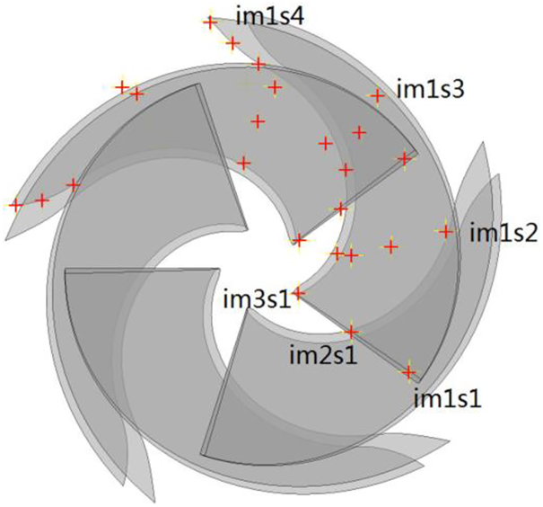
Figure 7: Position of the monitoring points in the impeller fluid domain
3.1 Comparative Analysis the Results of CFD and Tests
Figs. 8–10 show the comparative analysis of the bidirectional fluid-solid coupling and corresponding test results, all data in the figures are presented as ratios to the head or torque under rated operating conditions. In Figs. 8–10, (a) is the head comparison in the transient transition process of the rotor seizure accident, while (b) is the torque comparison; the mark “test” represents the test result, and the mark “fsi” represents the simulation result.

Figure 8: Comparison between fluid-solid coupling simulation results and test results of kz00
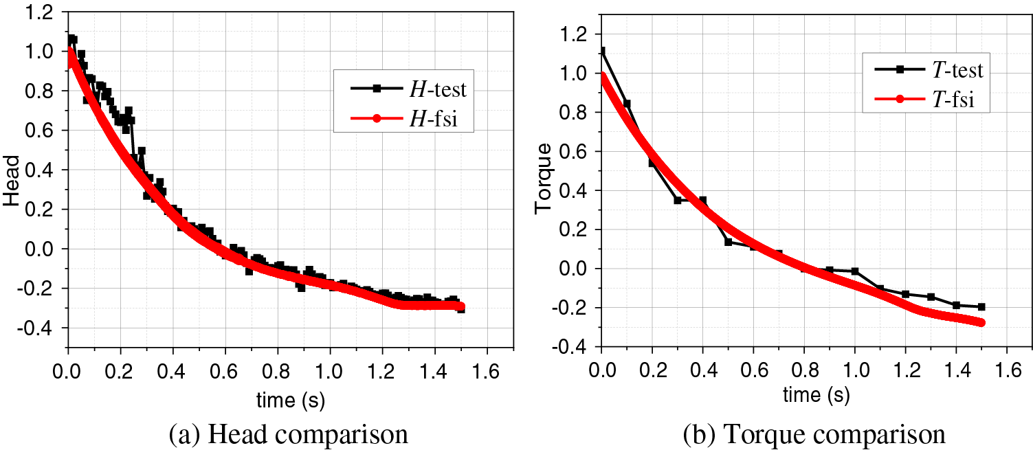
Figure 9: Comparison between fluid-solid coupling simulation results and test results of kz01
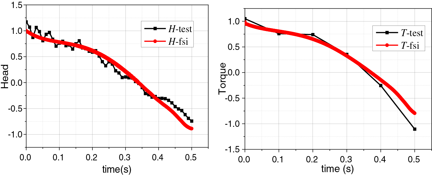
Figure 10: Comparison between fluid-solid coupling simulation results and test results of kz02
In kz00, for the head curves, except for the simulated values in [0.4 s, 1.1 s] are slightly smaller than test values, the maximum deviation is 9.5%, and the other parts of two curves exhibit high consistency; for the torque curves, the simulated values in [1.7 s, 2.7 s] are slightly smaller than test values, the maximum deviation is 6.7%. In kz01, for the head curves, the significant deviation occurs in [0.1 s, 0.3 s], and the maximum deviation is 9.6%; for the torque curves, the significant deviation occurs in [0.9 s, 1.5 s], and the maximum deviation is 7.1%. In kz02, the overall trend of the curves is consistent, but the deviation shows a noticeable increase due to the severe degree of rotor seizure and significant fluctuation of test data. For the head curves, the more significant deviations appear in [0 s, 0.1 s] and [0.4 s, 0.5 s], while for the torque, the more significant deviations appear in [0.38 s, 0.5 s].
In summary, the head curves show more significant deviations in the early and middle stages of the rotor seizure process for the three sets of comparative data. The torque curves exhibit more significant deviations, mainly in the later stages. The overall trend of the time-dependent variations of the head and torque obtained from fluid-solid coupling simulations is in good agreement with test results, demonstrating a high level of consistency. The maximum deviations of the transient torque and head simulated are within the acceptable range. This phenomenon demonstrates the accuracy of the mathematical models for flow rate and rotational speed constructed in MATLAB, used as boundary conditions. It confirms the high reliability of the bidirectional fluid-solid coupling simulation results.
3.2 Rotor Seizure Transient Model under Different Rotor Seizure Degrees
After the fluid-solid coupling, the transient models of kz00, kz01, and kz02 under different rotor seizure degrees were obtained, as shown in Fig. 11. The time point 0 represents the start of the rotor seizure, from which the test pump enters the rotor seizure transient transition process. Moreover, characteristic curves representing the temporal variations of rotational speed nt, flow rate Qt, torque T, and head H under different rotor seizure conditions were obtained.
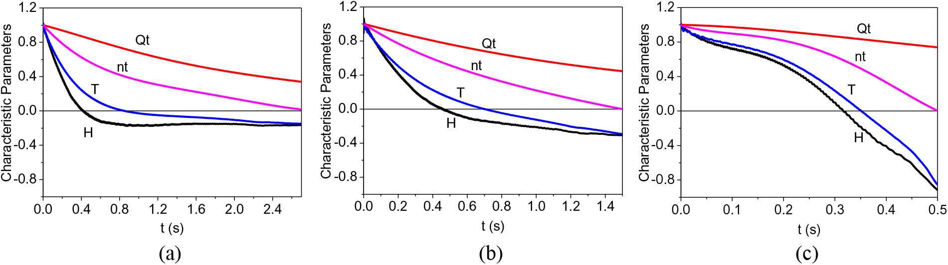
Figure 11: Transient model of (a) kz00 (b) kz01 (c) kz02 rotor seizure accident
By comparing three sets of data, it can be observed that, after entering the rotor seizure transient transition process, the rotational speed nt, flow rate Qt, torque T, and head H of kz00, kz01 and kz02 all exhibit nonlinear decreases until the rotational speed nt reaches zero. Particularly, torque T and head H continue to decrease beyond zero until reaching negative extremum values. Additionally, kz00 shows a tendency for the torque T and head H to approach a steady state in the latter half of the condition.
3.3 Transient Effect Analysis of Unsteady Head during the Transient Transition Process
In the RCP rotor seizure accident, the substantial transient acceleration of the rotor is the primary phenomenon during the transient transition process. At the same time, the flow rate, rotational speed and torque also rapidly vary with time. RCP is entirely out of steady-state operational condition, and the Euler equation is no longer applicable, and the rotor’s braking and coolant’s accelerations significantly impact the pump performance. In this unsteady transition process, the transient head of RCP at a specific moment is the sum of the steady-state head and the unsteady head in the corresponding transient condition, and the general equation of the impeller rotor during the transient process is as follows [18]:
where Hsu is the total theoretical head, m; Hs is the theoretical head of steady-state, m; Hu is the theoretical unsteady head, m; ρ is the density of the coolant, kg/m3; ω is instantaneous angle, rad/s; Qt is instantaneous flow, m3/s; Ωj is the rotational inertia constant of the fluid in the impeller region; ΩM is the flow inertia constant of the fluid in the impeller region; t is the time, s; D is the nominal diameter of the impeller, m.
The unsteady theoretical head Hu includes two parts: the rotational acceleration additional head Hu1, and the instantaneous head Hu2 caused by the acceleration of the coolant within the system pipeline, as follows:
where
The combination of Eqs. (12) and (13) indicates that the size of the impeller and the transient braking acceleration of the rotor play a leading role in the unsteady head of the pump in the rotor seizure accident. The influence of the impeller size on its unsteady head is more evident than the transient braking acceleration of the rotor. Therefore, when designing the hydraulic and structural aspects of the impeller, it is advisable to minimize the size while satisfying the design conditions, which can help alleviate the variation of the unsteady head during the transient transition process caused by accidents, enhancing the safety of the equipment and the primary loop system.
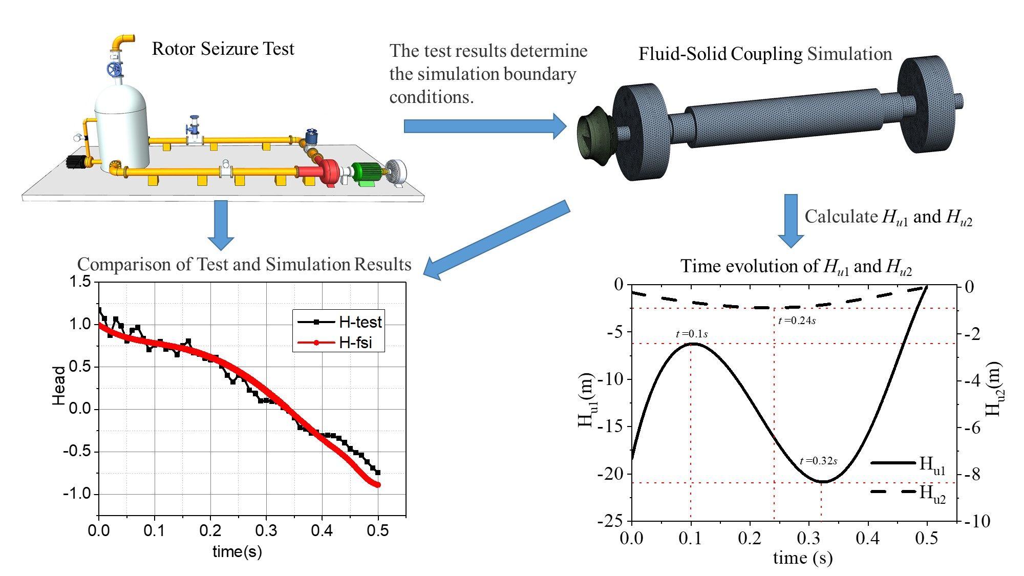
The following is a calculation and analysis of the unsteady theoretical head in the rotor seizure process of the transient model of kz02. After eliminating the influence of efficiency factors on the results during operation, the effects of rotor braking acceleration and inertia flow acceleration within the impeller on the transient head during the transient process are preliminary analyzed. Fig. 12 shows the time evolution diagram of the flow rate and rotational speed of test kz02. The time point 0 represents the start of the rotor seizure accident, and the accident ends at 0.5 s, which means the rotor seizure lasts 0.5 s. The figure shows that the flow rate and rotational speed decrease over time; the rotational speed completely changes to zero at 0.5 s, and the flow rate decreases from 4.968 to 3.672 m3/s. Moreover, the rate of change in rotational speed is much greater than that of flow rate throughout the process.
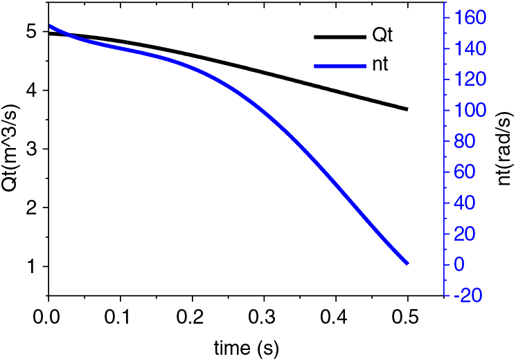
Figure 12: Time evolution of flow rate and rotational speed under the rotor seizure accident
Fig. 13 shows the time evolution curves of the rotational acceleration additional head Hu1 and the instantaneous head Hu2 obtained from the characteristic change curve of flow rate and rotational speed and the calculation of hydraulic structure parameters of the RCP impeller. Among these, the negative value represents the opposite direction when the head is in a steady state at the rated operating condition. Fig. 13 shows that the main component of the unsteady head Hu is Hu1, which contributes significantly more than Hu2. This is because, apart from the structural parameters of the impeller, Hu1 is primarily determined by the angular acceleration

Figure 13: Time evolution of Hu1 and Hu2 under the rotor seizure accident
Fig. 13 only depicts the variations of Hu1 and Hu2 in the transient process of the rotor seizure accident. In fact, the flow rate and transient head characteristics throughout the entire rotor seizure process are not only related to the structural parameters of the impeller but also closely linked to the characteristics of the primary loop pipeline system. In order to gain a more accurate and detailed understanding of the variations in unstable parameters during the rotor seizure process, it will be necessary for subsequent studies to consider the characteristics of the pipeline system in conjunction with the impeller’s parameters.
3.4 Transient Effect Analysis of the Flow during the Transient Transition Process
This section selected the transient model of kz02, which is the most severe degree of rotor seizure, and the transient turbulent kinetic energy, vorticity and pressure of each monitoring point were analyzed.
3.4.1 Analysis of Transient Turbulent Kinetic Energy and Vorticity inside the Pump
Turbulent kinetic energy is the most common physical quantity used to describe the degree of fluid turbulence pulsation. It can be used to measure the fluid viscous dissipation loss and the range of pulsation diffusion [19]. Fig. 14a is the transient turbulent kinetic energy change diagram of the monitoring points at the inlet of the impeller. The turbulent kinetic energy on the inlet edge is stable from the early stage to the middle stage of the transition process, and it can be found that at the monitoring points near the wall, im1p1, im1s1, im3p1 and im3s1 have more significant turbulent kinetic energy than at the monitoring points located in the intermediate streamline, im2p1 and im2s1. With the advance of the rotor seizure accident, the turbulent kinetic energy begins to change after 0.25 s, and the turbulent kinetic energy on the front and rear cover plate increases at the beginning and then decreases, that is, the curve posts a maximal value; the im3p1 and im3s1 extreme values near the rare cover plate appear earlier than im1p1 and im1p1 near the front cover plate. It is indicated that the rare cover plate transmits turbulence perturbation along the inlet side of the front cover plate.
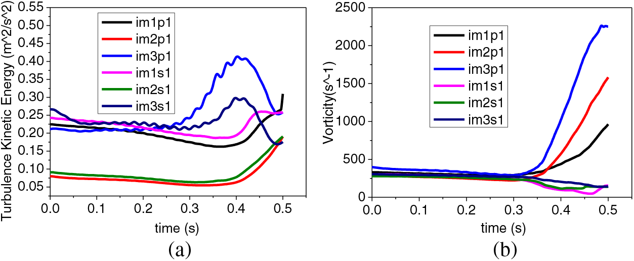
Figure 14: Transient (a) turbulent kinetic energy and (b) vorticity change of impeller inlet edge
In the analysis of fluid turbulent flow, vorticity is evidenced as an essential parameter in the study of the fluid field, and its analysis is a crucial tool to fully understand the intensity and development of the vortex motion in the transient process of the rotor seizure [20]. Fig. 14b shows the transient vorticity variations at each monitoring point on the impeller inlet’s pressure and suction surface of the impeller inlet. In the early stage of the transient process, the fluid vorticity at the inlet edge of the impeller is smaller and decreases with time, indicating that the overall fluid movement trend is minimally affected. Due to the inertia of the fluid, it continues to flow in its original state to a large extent, resulting in a relatively stable overall flow. In the later stage of the transient process, the vorticity at the monitoring points on the suction surface exhibits an overall decreasing trend while the variation amplitude increases. The vorticity at the monitoring points im1p1, im2p1, and im3p1 on the pressure surface of the blade inlet sharply increases and reaches 3 to 6 times the steady-state operating conditions at 0.5 s. The flow state inside the pump was found to change subversively, and the RCP made the rotor turn positively under the action of the negative head with a positive flow rate while the energy from the coolant was absorbed. The flow in the pump was found to be extremely disorderly, and the disturbance was found to be intense.
Fig. 15 illustrates the variations of transient turbulent kinetic energy and transient vorticity within the impeller flow passage. By comparing Figs. 15a and 15b, it can be observed that the transient turbulence kinetic energy and vorticity show some similarities in their variations; before 0.42 s, the transient turbulent kinetic energy and vorticity decrease slowly, and the transient turbulent kinetic energy is small and basically stable within 0.1 m2/s2, and the turbulence intensity is observed to gradually increase from inlet to outlet along the intermediate streamline (im2m1 < im2m2 < im2m3 < im2m4). Part of the reason was verified that the impeller outlet is close to the guide blade inlet side, and the flow process was affected by the rotor-stator interference of the impeller and guide blade. After 0.42 s, the other monitoring points’ transient vorticity and turbulent kinetic energy increased sharply except im2p1, which is far from the outlet edge. Because the energy supply speed of the impeller was far behind the energy carried by the inertial flow in the system pipeline and had fully entered the reverse pump condition, the impeller was no longer able to perform positive work on the fluid, and the pressure on the working surface of the impeller was lower than that on the back of the impeller, which generated a liquid loss rate with a large number of vortexes and secondary flows on the working face of the impeller, spreading rapidly into the flow passage. The monitoring point im2m4, located near the impeller outlet, experienced significant development due to the large initial pressure difference. While im2m1 was less affected due to its distance from the outlet and smaller initial pressure difference, the vorticity and turbulence kinetic energy decreased as a trend.
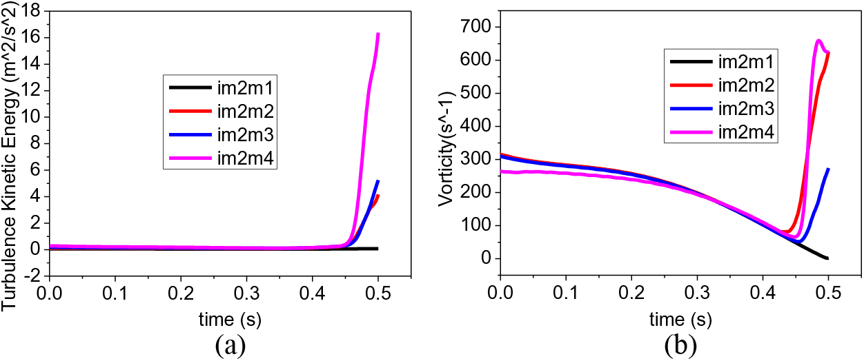
Figure 15: Transient (a) turbulent kinetic energy and (b) vorticity change in impeller passage
Fig. 16 illustrates the change curves of transient turbulent kinetic energy and transient vorticity at the outlet edge of the impeller. The turbulent kinetic energy on the suction surface was minimally affected, and its value decreased gradually as the flow rate decreased. In the later stage of the transient process, due to the change of work capacity of the impeller, the blade pressure surface was in the area of vortex generation, development and enhancement, leading to the turbulent kinetic energy rising sharply, indicating that the flow in the pump was volatile. The comparison between Figs. 14a and 16a show that the turbulent intensity at the outlet edge of the impeller is much larger than that at the inlet edge and is dozens of times higher. While the vortex value is exactly contrary, as shown in Figs. 14b and 16b. The vorticity values at the impeller inlet edge are several times higher than at the outlet edge. The reasons for this phenomenon are as follows: as the development of the rotor seizure accident, the flow rate and the rotational speed decreased rapidly while the decreasing rate of the rotational speed was greater, and as the rotor seizure accident entered the III phase to a certain moment, the actual transient flow rate in the system became greater than the pump characteristic flow rate at that rotational speed, which can be understood as the pump operating under high flow rate conditions at that rotational speed. According to the velocity triangle, the blade inlet edge was subjected to a negative impact angle, resulting in flow separation between the fluid flow and the pressure surface of the blade inlet; this led to the generation of vortices within this region, causing a sharp increase in vorticity at the inlet edge that intensifies with the progression of the rotor seizure accident. It should be noted that the monitoring point closer to the hub had the highest vorticity, followed by the intermediate streamline, and the monitoring point closer to the front cover plate had the lowest vorticity; this was due to the smaller radius at the hub side and the larger radius at the front cover plate side. Vortices formed near the hub side but weakened as they developed towards the front cover plate due to the influence of centrifugal and Coriolis forces. In addition, after the vortex formed from near the hub side of the blade inlet side, it gradually diffused to the outlet edge. However, due to the space distortion constraint of the impeller blade on the fluid, the rotational speed of the fluid micro-cluster was consistent with the flow rate of the impeller, thus suppressing the development of vortices. As a result, vortices formed near the impeller inlet and gradually dissipated in intensity as they progressed towards the outlet.
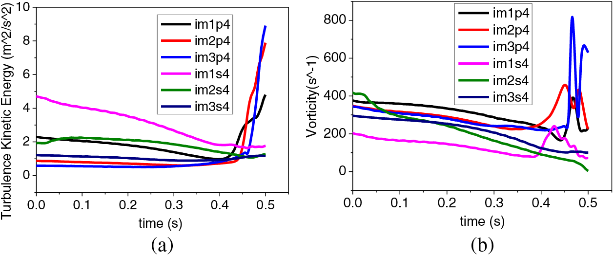
Figure 16: Transient (a) turbulent kinetic energy and (b) change of impeller outlet edge
3.4.2 Transient Pressure Change inside the Pump
Fig. 17a is the transient pressure variation of the impeller inlet edge, and the static pressure values on the pressure surface of the blade inlet are higher than those on the suction surface in the early stage of the transient process. With the development of the rotor seizure accident, the flow rate and rotational speed gradually decrease, reducing the impeller pressure surface static pressure, and the pressure values of im1p1, im2p1 and im3p1 finally tend to be close. Meanwhile, due to the insufficient vacuum at the impeller inlet, the pressure of im1s1, im2s1 and im3s1 on the suction surface exhibits a trend of initially increasing and then decreasing. After 0.3 s, the pressure difference between the pressure surface and the suction surface of the blade inlet gradually widens. In the later stage of the transient process [0.4 s, 0.5 s], the pressure values of the monitoring points im1p1, im2p1 and im3p1 alternate. The reason for this alternating phenomenon is the significant change in flow characteristics during the later stage of the transient process, resulting in increasingly insufficient flow and, localized impacts and secondary backflow.

Figure 17: Transient pressure change of (a) impeller inlet edge (b) impeller passage and (c) impeller outlet edge
Fig. 17b is the transient pressure variation in the impeller passage. Before the rotor seizure accident, there should be a noticeable pressure gradient from the inlet to the outlet of the impeller passage. As a result of the impeller’s output of coolant energy, the pressure of the monitoring points in the flow passage increases gradually from the inlet to the outlet (im2m1 to im2m4). However, after the rotor seizure accident occurrence, as the power output of the impeller to the coolant decreased, and the instantaneous flow rate and rotational speed decreased, the transient pressures at monitoring points im2m2, im2m3 and im2m4 gradually decreased with time, resulting in a gradual reduction in the pressure gradient. As for point im2m1, which is close to the impeller inlet, the coolant at this location was less influenced by the rotor seizure incident due to the weaker constraint from the blades, resulting in a transient pressure that basically remains stable at the same value. The pressure difference between the pressure surface and suction surface on the outlet edge gradually decreased, with the transient pressure values equaling around 0.36 s. Subsequently, the pressure on the suction surface surpasses that on the pressure surface, resulting in a state in which the impeller absorbs energy from the coolant at the outlet, causing the impeller to perform negative work.
Fig. 17c is the transient pressure variation of the impeller outlet edge, and It can be observed that the pressure at each monitoring point decreases with time in a pulsating manner, and the transient pressure variations on the outlet edge exhibit more regular patterns compared to those on the inlet edge. The pressure curves of the three monitoring points on the pressure surface overlap, and the same applies to the three monitoring points on the suction surface. Before the rotor seizure accident, the pressure on the outlet edge’s pressure surface should be significantly greater than that on the suction surface; this indicates that the blades were performing positive work on the coolant, transferring energy from the impeller to the coolant. By comparing with Figs. 17a and 17c, it is found that the time point at which the pressure surfaces and suction surfaces reach equality at the inlet edge occurs at around 0.3 s, while the occurrence of the pressure equality point on the outlet edge lags.
This paper studied the transient internal flow characteristics of the RCP at rotor seizure conditions based on bidirectional fluid-solid coupling. The internal flow evolution mechanism during the transition process of rotor seizure accident was investigated. Moreover, the primary results of the transient analysis of the structure field of the RCP were established.
(1) The bidirectional fluid-solid coupling simulation obtained the transient models of the rotor seizure accident under three different rotor seizure degrees. The head and torque simulating results were compared with test data, showing good agreement between the curves within an acceptable margin of error. It demonstrates the accuracy of the boundary conditions, the tested transient flow rate, and rotational speed and validates the reliability of the coupled simulation results for rotor seizure.
(2) The transient effect of the unsteady head in the process of the rotor seizure accident was analyzed. It was found that the size of the impeller and the rotor braking acceleration play a leading role in the unsteady head. Moreover, a small size is suggested as far as possible on the premise of satisfying the design conditions in the hydraulic and structural design of the impeller to alleviate unsteady head changes in the transient process of RCP caused by accident and enhance the safety of equipment and primary loop system.
(3) In the transient process of the rotor seizure accident, the unsteady head Hu involves the rotational acceleration of additional head Hu1 and instantaneous head Hu2 caused by the acceleration of the coolant within the system pipeline. Hu1 is much more significant in the transient process of rotor seizure than Hu2, and Hu2 is a parabolic function curve. Two extreme points in Hu1 appeared along with the evolution of the rotor seizure time, which generally follows a cubic polynomial function.
(4) During the transient process of the RCP rotor seizure accident, there is a drastic change in the turbulent kinetic energy and vorticity at the impeller inlet and outlet, resulting in a disruptive internal flow state. Furthermore, the fluid field pressure in the vicinity of the blade inlet and outlet was verified to be very different.
Acknowledgement: Appreciation is extended to China Nuclear Power Engineering Co., Ltd., for providing substantial technical support for the Reactor Coolant Pump Rotor Seizure tests.
Funding Statement: National Natural Science Foundation Joint Fund Key Project (U20A20292). Task Book for Shandong Provincial Science and Technology Small and Medium-Sized Enterprise Innovation Capability Enhancement Engineering Project (2023TSGC0005).
Author Contributions: The authors confirm contribution to the paper as follows: study conception and design: Weiyuan Zhong, Xiuli Wang; data collection: Weiyuan Zhong, Mengdong An; analysis and interpretation of results: Mengdong An, Weiyuan Zhong, Wei Xu; draft manuscript preparation: Mengdong An, Weiyuan Zhong. All authors reviewed the results and approved the final version of the manuscript.
Availability of Data and Materials: Data available on request. The data underlying this article will be shared on request to the corresponding author.
Conflicts of Interest: The authors declare that they have no conflicts of interest to report regarding the present study.
References
1. Wang, X., Lu, Y., Zhu, R., Fu, Q., Chen, Y. et al. (2019). Study on the transient evolution law of internal flow field and dynamic stress of reactor coolant pump under rotor seizure accident. Annals of Nuclear Energy, 133, 35–45. https://doi.org/10.1016/j.anucene.2019.05.001 [Google Scholar] [CrossRef]
2. El-Sahlamy, N. M., Selim, H. K. (2021). Modeling of flow coastdown transient of a reactor coolant system under different pump failures. Annals of Nuclear Energy, 164. [Google Scholar]
3. Veluri, V. K., Sengupta, S. (2023). Thermal-hydraulic transient analyses for primary coolant system of HFRR using RELAP5. Nuclear Technology, 209, 765–776. https://doi.org/10.1080/00295450.2022.2156245 [Google Scholar] [CrossRef]
4. Lu, Y., Long, Y., Zhu, R., Wang, Z., Wang, X. (2021). Transient structural load characteristics of reactor coolant pump rotor system in rotor seizure accident. Annals of Nuclear Energy, 164. [Google Scholar]
5. Ping, Y., Hongyi, J., Zhe, W. (2013). Preliminary research on RTDP methodology for advanced LPP thermal-hydraulic design. Atomic Energy Science & Technology, 47(7), 1182–1186. [Google Scholar]
6. Wang, X., Lu, Y., Zhu, R., Fu, Q., Chen, Y. et al. (2020). Experimental study on transient characteristics of reactor coolant pump under rotor seizure accident. Annals of Nuclear Energy, 136, 107039. [Google Scholar]
7. Souli, M., Aquelet, N. (2011). Fluid structure interaction for hydraulic problems. Houille Blanche-Revue Internationale De L Eau, 97(6), 5–10. https://doi.org/10.1051/lhb/2011054 [Google Scholar] [CrossRef]
8. Bazilevs, Y., Takizawa, K., Tezduyar, T. E. (2013). Challenges and directions in computational fluid-structure interaction. Mathematical Models & Methods in Applied Sciences, 23, 215–221. https://doi.org/10.1142/S0218202513400010 [Google Scholar] [CrossRef]
9. Li, Q., Li, B., Li, X. W., Xie, Q. T., Liu, Q. L. et al. (2023). Study on transient performance of tilting-pad thrust bearings in nuclear pump considering fluid-structure interaction. Nuclear Engineering and Technology, 55, 2325–2334. https://doi.org/10.1016/j.net.2023.03.007 [Google Scholar] [CrossRef]
10. Weng, Y., Wang, H., Wang, H., Liu, J., Pan, J. et al. (2022). The thermal-fluid-solid coupling effect in nuclear reactor vessel with direct vessel injection. Progress in Nuclear Energy, 152, 104364. https://doi.org/10.1016/j.pnucene.2022.104364 [Google Scholar] [CrossRef]
11. Cuamatzi-Melendez, R., Flores-Cuamatzi, E. (2020). Modelling fluid-structure interaction of water recirculating flow to predict damage and/or failure in a jet-pump assembly of a nuclear boiling water reactor. Engineering Structures, 206, 110155. https://doi.org/10.1016/j.engstruct.2019.110155 [Google Scholar] [CrossRef]
12. Wang, X., Lu, Y., Zhu, R., Fu, Q., Yu, H. et al. (2019). Study on bidirectional fluid-solid coupling characteristics of reactor coolant pump under steady-state condition. Nuclear Engineering and Technology, 51, 1842–1852. https://doi.org/10.1016/j.net.2019.05.009 [Google Scholar] [CrossRef]
13. Seok, W., Lee, S. B., Rhee, S. H. (2019). Computational simulation of turbulent flows around a marine propeller by solving the partially averaged Navier-Stokes equation. Proceedings of the Institution of Mechanical Engineers, Part C: Journal of Mechanical Engineering Science, 233, 6357–6366. [Google Scholar]
14. Wu, J., Li, J., Qiu, X., Xie, X., Liu, Y. (2021). Machine learning based Reynolds averaged simulation of backward-facing step flows at different Reynolds numbers. Modern Physics Letters B, 35(25), 2150430. https://doi.org/10.1142/S0217984921504303 [Google Scholar] [CrossRef]
15. Bajpai, S., Nataraj, N., Pani, A. K. (2013). On fully discrete finite element schemes for equations of motion of kelvin-voigt fluids. International Journal of Numerical Analysis and Modeling, 10, 481–507. [Google Scholar]
16. Leigh, E. J., Kunz, D. L. (2007). Simulation of a moving elastic beam using Hamilton’s weak principle. Aiaa Journal, 45, 471–476. https://doi.org/10.2514/1.25418 [Google Scholar] [CrossRef]
17. Ziolkowski, P. J., Ochrymiuk, T., Eremeyev, V. A. (2021). Adaptation of the arbitrary Lagrange-Euler approach to fluid-solid interaction on an example of high velocity flow over thin platelet. Continuum Mechanics and Thermodynamics, 33, 2301–2314. https://doi.org/10.1007/s00161-019-00850-7 [Google Scholar] [CrossRef]
18. Meng, D., Yan, R., Sun, L., Liu, E., Zhang, H. (2010). Study on the leak detection system with cryopump as main pump. Vacuum, 47(6), 33–36. [Google Scholar]
19. Guerrero, B., Lambert, M. F., Chin, R. C. (2023). Transient behaviour of decelerating turbulent pipe flows. Journal of Fluid Mechanics, 962, A44. https://doi.org/10.1017/jfm.2023.294 [Google Scholar] [CrossRef]
20. Shao, C. L., Yang, S. L., Xu, K. J., Zhu, Q. L. (2022). Parameter identification method for transient impact interference of vortex sensor based on optimal estimation of objective function. IEEE Transactions on Instrumentation and Measurement, 71, 1–10. [Google Scholar]
Cite This Article
 Copyright © 2024 The Author(s). Published by Tech Science Press.
This work is licensed under a Creative Commons Attribution 4.0 International License , which permits unrestricted use, distribution, and reproduction in any medium, provided the original work is properly cited.
 Downloads
 Citation Tools