
 Submit a Paper
 Propose a Special lssue
 Open Access
ARTICLE

Optimal Design of High-Speed Partial Flow Pumps using Orthogonal Tests and Numerical Simulations
1 National Research Center of Pumps, Jiangsu University, Zhenjiang, China
2 Wenling Fluid Machinery Technology Institute of Jiangsu University, Wenling, China
3 National Engineering Research Center for Disaster and Emergency Rescue Equipment, Army Logistics Academy, Chongqing, China
* Corresponding Author: Yu Zhang. Email:
Fluid Dynamics & Materials Processing 2024, 20(6), 1203-1218. https://doi.org/10.32604/fdmp.2023.045825
Received 08 September 2023; Accepted 28 November 2023; Issue published 27 June 2024
 View Full Text
 Download PDF
Abstract
To investigate the influence of structural parameters on the performances and internal flow characteristics of partial flow pumps at a low specific speed of 10000 rpm, special attention was paid to the first and second stage impeller guide vanes. Moreover, the impeller blade outlet width, impeller inlet diameter, blade inclination angle, and number of blades were considered for orthogonal tests. Accordingly, nine groups of design solutions were formed, and then used as a basis for the execution of numerical simulations (CFD) aimed at obtaining the efficiency values and heads for each design solution group. The influence of impeller geometric parameters on the efficiency and head was explored, and the “weight” of each factor was obtained via a range analysis. Optimal structural parameters were finally chosen on the basis of the numerical simulation results, and the performances of the optimized model were verified accordingly (yet by means of CFD). Evidence is provided that the increase in the efficiency and head of the optimized model was 12.11% and 23.5 m, respectively, compared with those of the original model.Keywords
Nomenclature
| H | Head (m) |
| Q | Flow rate (m³/h) |
| a | Impeller blade outlet width (mm) |
| b | Impeller inlet diameter (mm) |
| z | The number of blades (slice) |
| α | The blade number (slice) |
| η | Pump efficiency (%) |
| ns | Specific speed |
A partial flow pump, also known as a tangential pump, is considered a high-speed pump when its speed exceeds 3600 r/min. Its overcurrent components differ from those of ordinary centrifugal pumps. This new type of pump was developed based on innovative theories [1,2]. A partial flow pump is a low specific speed pump with a small flow rate and high lift. Compared with a centrifugal pump, it has several advantages such as compact structure, superior component interchangeability, longer lifespan, reliable operation, smaller axial force, and flatter head curve. Partial flow pumps are widely used in aerospace, fertilizer, pharmaceutical, and petrochemical industries [3,4]. They are mainly used for petrochemicals and aerospace applications, and the transported liquid’s properties have a significant impact on the pump’s operation and performance, such as specific gravity, viscosity, and concentration. When the medium’s specific gravity increases, the pump’s shaft power increases. As the viscosity and concentration increase, the same flow rate results in a shorter distance transported by the pump, resulting in a decreased pump head. Although the constant head characteristic of partial flow pumps makes changes in medium viscosity and density insignificant on the head, high-speed pumps handling denser media such as petroleum can lead to accidents in high-speed shaft bearings during operation. Through extensive experimental research, researchers have proposed specific corrective measures to make partial flow pumps suitable for oil extraction and transportation [5–8].
Barske and Turton developed the fundamental design theory for tangent pumps through extensive research and pointed out that partial flow pumps, like conventional centrifugal pumps, follow Turton’s equation. However, unlike conventional centrifugal pumps, in the impeller of a partial flow pump, the liquid rotates around the radius in a concentric rotational motion based on energy, and the impeller and fluid maintain a rigid relationship. When the liquid in a single flow channel connects to the diffuser along the tangential direction, it is discharged [9,10]. Ueda et al. [11] investigated the impact of impeller blade number on pump performance through simulation and experimentation. They found that as the number of blades increases, the flow velocity fluctuations in the pump decrease in frequency, and the flow path becomes smaller, leading to an increase in losses within the pump. Knyazeva explored the basic hydraulic characteristics of partial-flow pumps and determined the correlation between the changes in energy parameters and the kinematic viscosity of the liquid by numerical calculations [12]. Lee et al. [13] investigated the flow characteristics of partial flow pumps with small flow rates and high heads and studied the effect of the throat area on the pressure distribution within the pump. They also optimized the design of the pump structure based on their findings. Yu [14] investigated the flow characteristics of partial flow pumps by maintaining a constant head. It was found that as the flow rate increases, the impeller diameter and specific speed also increase, while the head coefficient ψ decreases. By keeping the flow rate of the partial flow pump constant, it was observed that increasing the throat diameter leads to improved pump efficiency and helps avoid significant decreases in the head caused by flow fluctuations. Li et al. [15] investigated the head characteristic curve of high-speed partial flow pumps as well as the factors that lead to hump phenomena. The research found that neither impeller diameter nor nozzle diameter has a significant effect on eliminating hump characteristics while adding an orifice plate at the outlet of the impeller can effectively address the issue. Yang et al. [16] utilized CFD technology to investigate the influence of throat nozzle area on the performance characteristics of partial flow pumps. It was found that when the throat nozzle area varied between 0.7 dt and 1.3 dt, the head remained essentially unchanged. Furthermore, the operating range of the pump expanded as the nozzle area increased, and the efficiency of the partial flow pump was directly correlated with the size of the throat nozzle area. Yang et al. [17] conducted a numerical simulation to investigate the impact of the number of blades and the outer diameter of the impeller on the performance of the partial flow pump. The research showed that the number of blades in the partial flow pump is inversely proportional to the head, while the outer diameter of the impeller has a quadratic relationship with its head.
In summary, current research and analysis on partial flow pumps have been conducted to some extent. Some scholars have explored the influence of certain structural parameters, such as impeller diameter, volute throat area, and clearances between the impeller and volute casing, on the flow characteristics within the pump. However, the focus of these studies has been primarily limited to single-stage partial flow pumps, which consist of assembled impellers and volute casings. The object of this study is a 14-stage low-specific-speed partial flow pump with a maximum speed of 10000 r/min, which has an impeller and guide vane assembly structure. Currently, there is little research on the optimization of impeller structural parameters for this type of pump. Therefore, in this paper, four factors including the outlet width (a) of the impeller blades, the inlet diameter (b) of the impeller, the inclination angle (α) of the impeller blades, and the blade number (z) are selected as experimental factors for impeller optimization design. The orthogonal test method is used to optimize the impeller design with the head and efficiency of the partial flow pump as the optimization objectives. The obtained optimization results are analyzed, and an ideal target model with both high efficiency and head is derived.
2 Pump Model and Orthogonal Test Scheme
The axial and radial dimensions were limited to 406 and 92 mm, respectively, in the actual application. The pump consisted of 14 stages with a design head height of 1000 m, a flow rate of 1.25 m3/h, and an efficiency of 46.83%. Table 1 provides the main geometric parameters of the high-speed multistage partial flow pump. To enhance optimization efficiency, the modeling simulation and orthogonal testing focused on the first and second stages of the multistage pump. Figs. 1 and 2 illustrate the model structure and impeller structure, respectively. The obtained influence law of each parameter on the pump performance reflects their impact on the multistage pump’s overall performance.
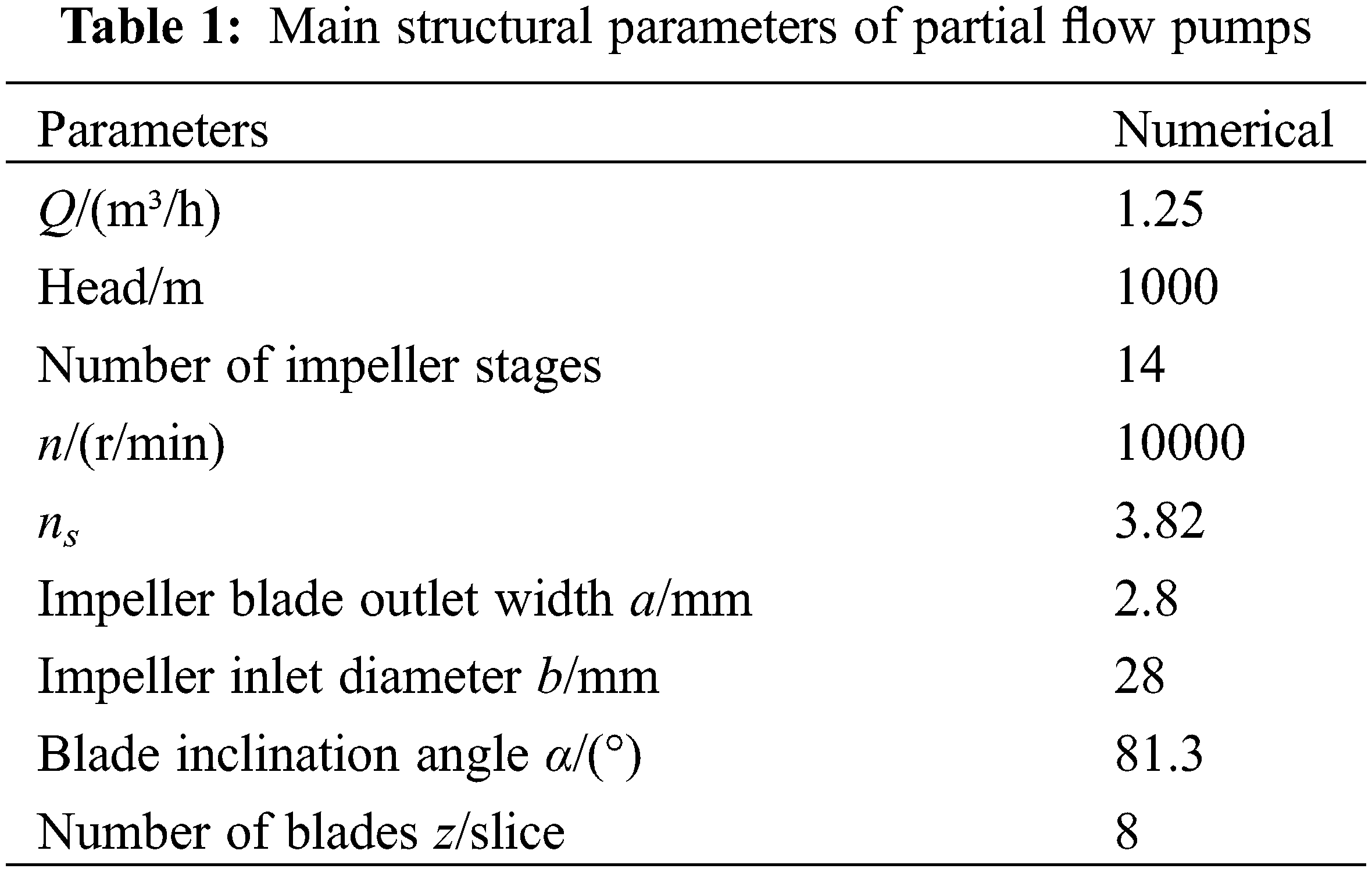

Figure 1: Assembly drawing of high-speed multistage partial flow pump

Figure 2: High-speed multistage partial flow pump impeller structure
(1) Investigate the influence of geometric parameters of partial flow pump impellers on the efficiency and head at the rated operating point.
(2) Propose an optimal design solution for a partial flow pump with a flow rate of Q = 1.25 m³/h, head of H = 1000 m, rotational speed of n = 10000 r/min, and specific speed of ns = 3.82.
2.2.2 Test Factors and Test Scheme
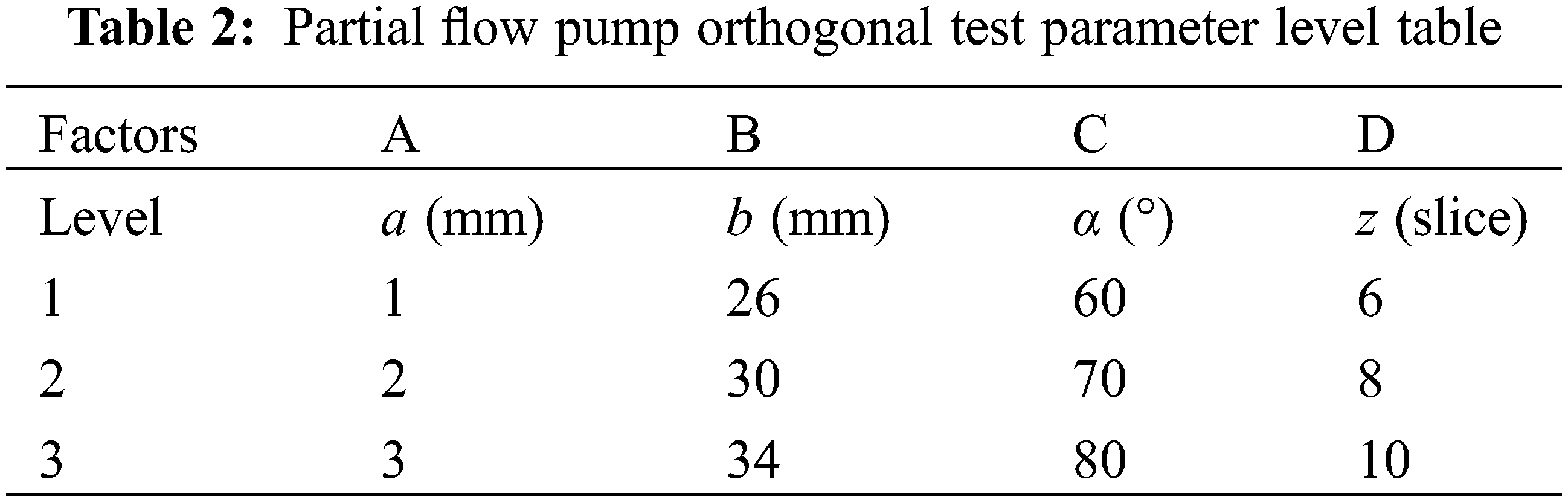
A thorough analysis was carried out to investigate the impact of various structural parameters on the performance of the partial flow pump. Four parameters, namely impeller blade outlet width (a), impeller inlet diameter (b), blade inclination angle (α), and number of blades (z), were chosen as orthogonal experimental factors. Each factor was set at 3 levels in order to meet the compact design requirements of the partial flow pump structure. Specifically, the impeller blade outlet width was set at 1, 2, and 3 mm, the impeller inlet diameter was set at 26, 30, 34 mm, the blade inclination angle was set at 60°, 70°, and 80°, and the number of blades was set at 6, 8, and 10. The level table for the experimental factors can be found in Table 2.
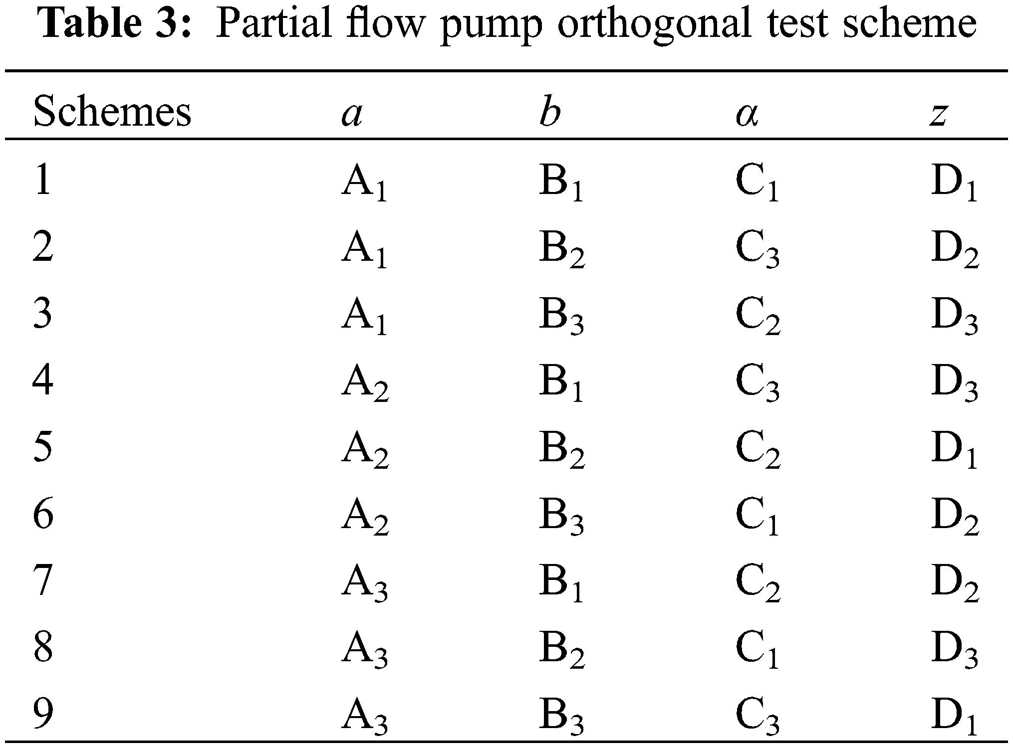
Nine sets of orthogonal tests were conducted, where appropriate parameter combinations were determined based on the selected orthogonal test factors and factor levels to generate an orthogonal table, as shown in Table 3. In this table, the letters A, B, C, and D represent impeller blade outlet width (a), impeller inlet diameter (b), blade inclination angle (α), and number of blades (z), respectively.
The three-dimensional model of the partial flow pump was meshed using the ICEM software in the ANSYS platform. In particular, a hexahedral structured mesh was applied to the impeller while the impeller blade area was locally refined. The remaining components of the overflow were set as an unstructured mesh. Moreover, a boundary layer was defined for all mesh models to minimize computational errors [18,19]. To ensure the accuracy of numerical simulations and minimize the number of grids for improved work efficiency, a grid independence analysis was conducted on the computational domain grid model, considering the efficiency and head simulation accuracy of the ultra-low specific speed magnetic pump, as well as the time required for computer numerical simulation. Six different scale mesh schemes were set for all calculation domains to obtain the optimal mesh number for the numerical simulation of pump models. Numerical simulations were performed on the six schemes under the rated flow condition, and the relationship between efficiency data and grid number was comprehensively compared and analyzed. The mesh model with no significant change in efficiency with increasing number of grids was selected as the best combination. As shown in Fig. 3, efficiency gradually increases with the increase in grid number, and the number of grids greatly affects efficiency when the grid number is less than that of scheme 5. When the number of grids continues to increase, the hydraulic efficiency of the pump no longer changes significantly with the change in the number of grids. Therefore, the mesh combination of scheme 5 was chosen for subsequent numerical simulation analysis, and the specific mesh model is illustrated in Fig. 4.

Figure 3: Grid independence verification
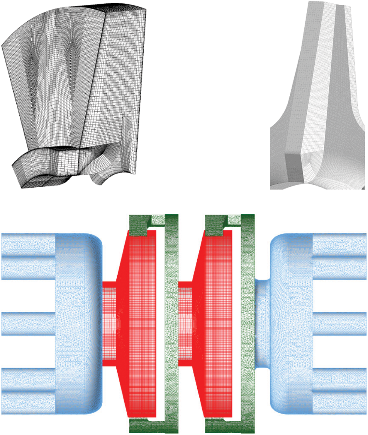
Figure 4: Mesh of impeller and guide vanes
The ANSYS CFX 2020R2 software was utilized to conduct simulations and analyses of nine different test scenarios. The boundary conditions for the model were set based on actual application scenarios.
For all computational domains, the fluid within the impeller was defined as a rotating domain, while other domains such as the inlet section, guide vanes, and outlet section were defined as stationary domains. To ensure smooth data transfer between independent computational domains and to replicate the actual working conditions of the pump, a moving-stationary interface was established at the connection between the stationary and rotating domains. Additionally, a stationary-stationary interface was set up at the connection between two stationary domains. The no-slip wall condition was applied to all convective wall surfaces. The rotating domain was defined with the z-axis as the rotation axis, and the rotational direction of the impeller was determined using the right-hand rule. The rotational speed of the domain was set to 10000 r/min. In terms of the inlet boundary condition, the computational domain’s inlet was designated as a pressure inlet with the inlet pressure equivalent to standard atmospheric pressure. On the other hand, the outlet was configured as a mass flow outlet with a mass flow rate of 1.25 m³/h. The rotor rotation is set to 3° per time step in this study. Combined with the rotational speed calculation, each time step corresponds to a duration of 0.00005 s. The maximum number of iterations is set to 2000 steps. In numerical computations, the residual values are used as a criterion to determine convergence. The average residual convergence tolerance is set to 1 × 10⁻⁵ [20]. During the iterative calculations, if the computation fails to converge, it is necessary to modify control parameters or adjust the grid of the computational domain. The governing equations, including the second-order upwind discretization scheme, are employed to discretize the continuity equation, momentum equation, turbulent kinetic energy equation, and turbulent dissipation rate equation. The finite volume method is utilized to discretize the governing equations, and the coupling between velocity and pressure is achieved using the SIMPLEC algorithm [21].
The conservation laws of fluid flow can be described by a set of governing equations composed of the mass equation, momentum equation, and energy equation. In this study, the fluid inside the pump is assumed to be incompressible, and the heat transfer process is neglected during the calculation. Therefore, the energy equation is omitted, and the mass equation and momentum equation serve as the fundamental governing equations for the fluid flow inside the pump. Considering the rotation of the fluid around the pump axis, the incompressible mass equation and momentum equation in the rotating coordinate system are as follows [22]:
where u is the relative velocity of the fluid, τ is the stress tensor, s is the source term, Ω is the angular velocity, r is the position vector.
In this study, a full-flow channel simulation of a high-speed multistage partial flow pump is performed using the standard k-epsilon (k-ε) turbulence model, which is widely used in CFD. The standard k-ε turbulence model assumes that the turbulent viscosity is isotropic, i.e., the ratio of Reynolds stress to deformation rate is the same in all directions. In the standard k-ε turbulence model, the turbulent viscosity μt is defined as [23]:
where Cμ is the empirical coefficient with a value of 0.09, ε is the turbulent kinetic energy dissipation rate, k is the turbulent kinetic energy.
The constraint equation for turbulent kinetic energy dissipation rate ε and the control equation for turbulent kinetic energy k are as follows:
Pk is the pressure generation term caused by the velocity gradient, and its mathematical expression is as follows:
The parameters in the equation are empirical coefficients, where σk = 1, σε = 1.3, c1 = 1.44, and c2 = 1.92.
The numerical simulation can be obtained from the partial flow pump inlet and out-let pressure parameters, from which the pump head can be calculated using the formula shown in Eq. (8). According to the action of fluid in the partial flow pump on the impeller wall torque, pump inlet and outlet pressure, and flow parameters, the partial flow pump operating efficiency can be calculated using Eq. (9) [24]:
where Pin is the pump inlet pressure, Pout is the pump outlet pressure, ρ is the fluid density, g is the gravitational acceleration, T is the impeller wall torque, w is the angular velocity.
According to the orthogonal test design scheme in Table 2, the hydraulic model of each scheme was established. The numerical simulation of each scheme model was conducted under the same working conditions to obtain the efficiency η and head H data under the rated working conditions. The numerical calculation results were post-processed according to the above calculation method, and the efficiency and head results of the nine test schemes are shown in Table 4.
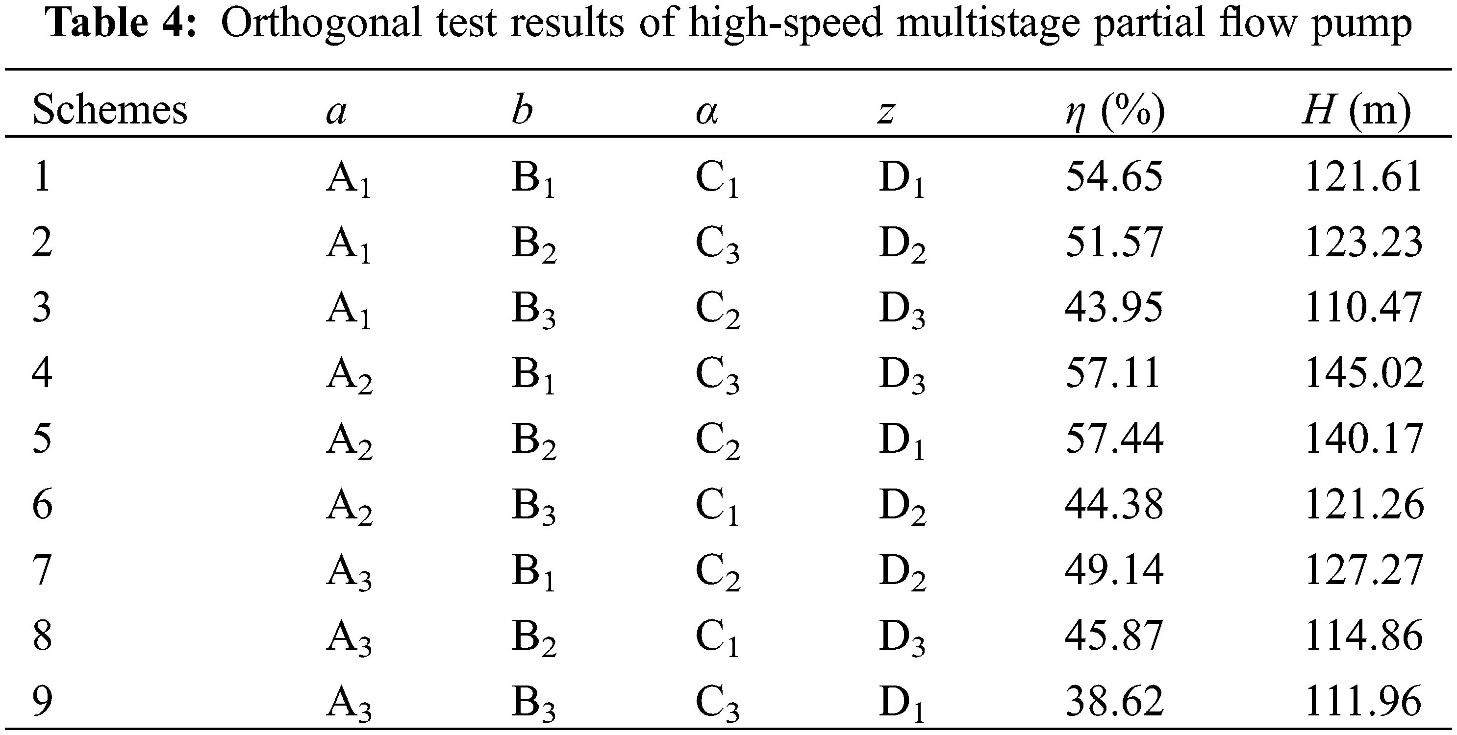
An extreme difference analysis was performed on the efficiency η and head H results of each test group to analyze the influence of four test factors on the performance of partial flow pumps. The aim was to identify the main parameters that affect the performance of partial flow pumps and ultimately determine the optimal combination of parameters. The range analysis of efficiency η is presented in Table 5.
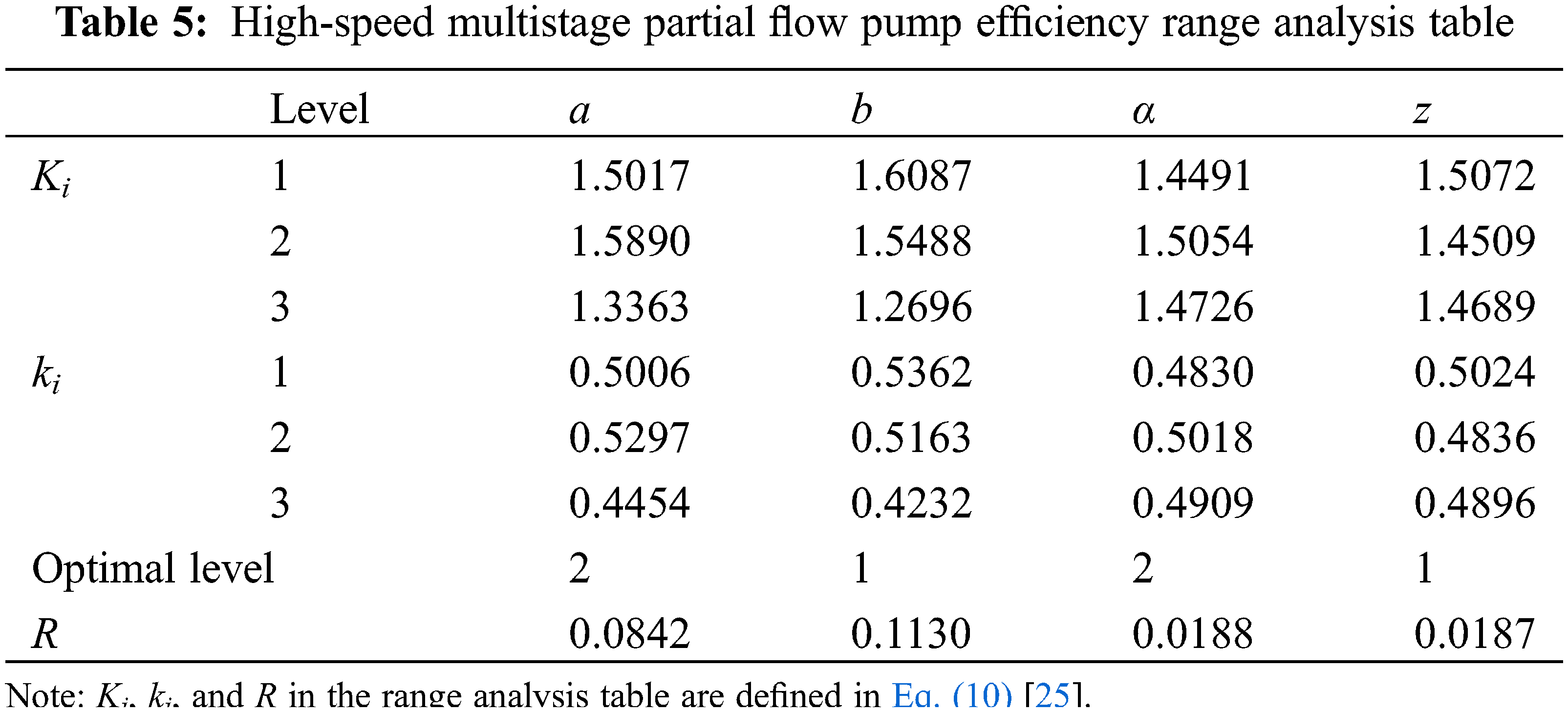
where Ei is the value of a factor, Ki is the sum of the values of j horizontal factors, ki is the mean value of each factor, and R is the range.
Table 4 shows that the impeller inlet diameter (b) has the greatest impact on the efficiency, the blade outlet width (a) is second, the blade inclination angle (α) and the number of blades (z) have a similar effect on the partial flow pump efficiency effect, and the impact efficiency is relatively small, i.e., Rb > Ra > Rz > Rα. The relationship between partial flow pump efficiency η and the 4 test factors is shown in Fig. 5. The partial flow pump efficiency increases and then decreases as the blade outlet width increases. The pump efficiency gradually decreases as the impeller inlet diameter increases, with a less significant decrease when the inlet diameter increases from 26 to 30 mm, and a more significant decrease from 30 to 34 mm. The blade inclination angle increases, causing the efficiency to rise first and then fall, but the efficiency change is small. The efficiency decreases first and then increases as the number of impeller blades increases, and the change is smoother.
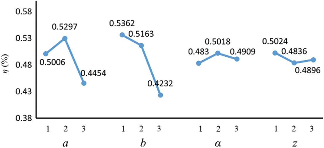
Figure 5: Relationship between efficiency and various factors
High-speed multistage partial flow pump head H extreme difference analysis as shown in Table 6. Based on the extreme difference value R shows that the impeller blade outlet width (a) on the head H influences the most, followed by the impeller inlet diameter (b), blade inclination angle (α) on the head H, and impeller blade number (z) on the head H, i.e., each parameter for the head H influence in the order Ra > Rb > Rα > Rz.
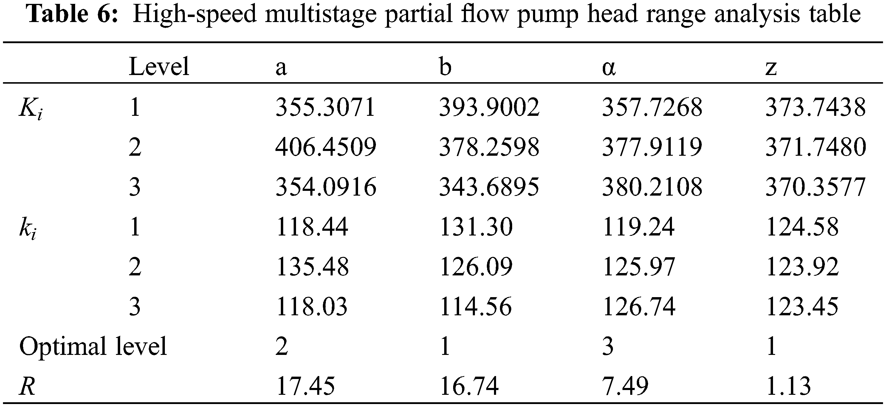
The relationship between head H and the 4 factors is shown in Fig. 6. When the blade outlet width (a) is increased, the amplitude of the head H change increases.
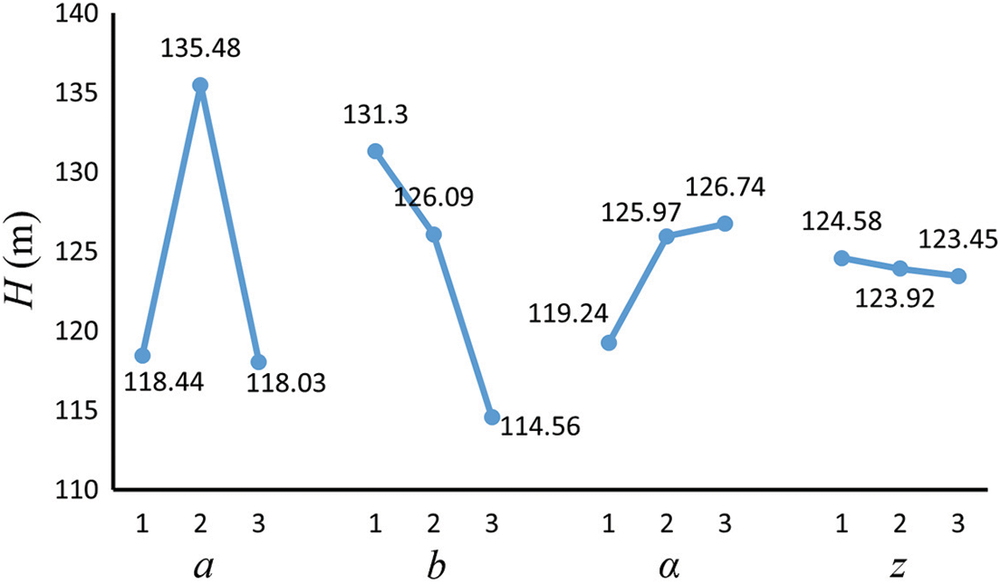
Figure 6: Relationship between the head and each factor
When the pump outlet flow rate Q is constant, the fluid flow rate decreases as the impeller inlet diameter (b) increases, lowering the pump head H. Head H increases with the increase of blade inclination angle (α), and head H rise amplitude is larger for blade inclination angle (α) from 60° to 70° stage. However, from the 70° to 80° stage, the head H rise amplitude is smaller, showing a slowly rising trend. An increase in blade number (z) makes the head show a slow decline trend.
Combining the above analysis, the specific levels of each of the 4 parameters are determined as follows:
(1) For the blade outlet width (a), level 2 is optimal when efficiency η is the selection criterion; level 2 is also optimal when pump head H is the selection basis; from the relationships between efficiency η, head H, and the factors, it can be seen that with an increase in blade outlet width (a), a trend of first increasing and then decreasing is observed. When the outlet width is selected as level 2 to obtain the maximum, the blade outlet width (a) selected level 2, corresponding to the value of 2 mm;
(2) When the efficiency η and pump head H are used as the selection criteria, the best level for the impeller inlet diameter (b) is 1. As the impeller inlet diameter (b) increased, the efficiency η and head H tended to decrease. Therefore, impeller inlet diameter (b) selects level 1 as the best level, corresponding to a value of 26 mm;
(3) For the blade inclination angle (α), the best level was 2 when the efficiency η was the basis for selection, and when the pump head H was the basis for selection, level 3 was the best. Blade inclination angle (α) from horizontal 2 changed to horizontal 3, i.e., blade inclination angle (α) changed from 70° to 80°, the head H only raised 0.77 m, and efficiency η reduced by 1.09%. Therefore, careful consideration of efficiency η and head H, blade inclination angle (α) chooses horizontal 2, that is, take the value of 70°;
(4) For the number of blades (z), with efficiency η as the selection basis, Level 1 is the best, and with the pump head H as the selection basis, Level 1 is the best. Therefore, the number of blades (z) chosen level 1, that is, the number of impeller blades (z), takes the value of six.
In summary, the design values of the four parameters of the high-speed multistage partial flow pump were determined by the orthogonal test method: blade outlet width a = 2 mm, impeller inlet diameter b = 26 mm, blade inclination angle α = 70°, and the number of blades z = 6. This combination, now referred to as scheme 10, was not included in the previously described nine sets of orthogonal schemes. Modeling, meshing, and numerical simulations were conducted for Scheme 10.
5 Performance Comparison before and after Optimization
5.1 Comparison of Pump Performance
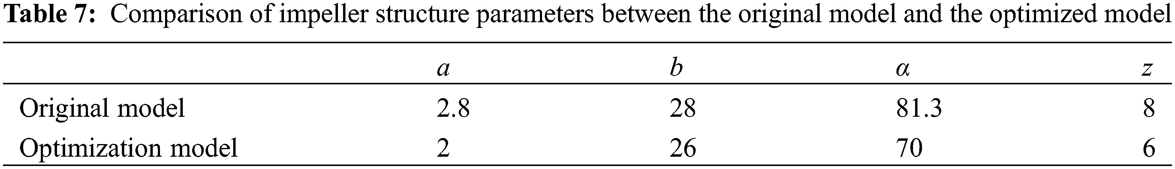
The optimal solution obtained from the orthogonal experiment, designated as Solution 10, was subjected to numerical analysis and compared with the performance of the prototype pump. The comparison of the optimization model and the prototype pump’s structural parameters is presented in Table 7, while the comparison of their characteristic curves is illustrated in Fig. 6.
The comparison of the curves in the figure, reveals that the head of the optimized model is lower than the head of the prototype pump when the flow rate is less than 0.8 times the rated flow rate. The working conditions in this range deviate from the rated working conditions to a greater extent. Thus, the optimization effect is not obvious. When the flow rate was 0.8 times the rated flow rate and above, the head of the optimized model was higher than that of the prototype pump, and the maximum value occurred at the rat-ed flow rate. Since the partial flow pump is a constant head pump, its outlet pressure is less affected by the change in flow rate, and the prototype pump and the optimized model head fluctuation range are maintained within 10%. As seen in Fig. 7, when the flow rate is 0.6 times the rated flow rate and above, the efficiency η of the optimized model is higher than that of the prototype pump. The difference between the efficiency η and head H of the prototype pump and the optimized model is smaller when the flow rate is the rated flow rate, the optimized model can get the optimal effect, and the head H is increased by 23.5 m. The efficiency η was increased by 12.11% compared to the original model.
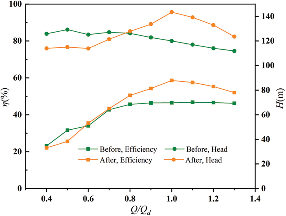
Figure 7: Comparison of the characteristic curves before and after optimization
5.2 Comparison of Pressure Distribution
The internal flow field data of the partial flow pump were obtained by postprocessing the numerical simulation results to analyze the flow mechanism of the internal flow field. A comparison of the impeller pressure fields is shown in Fig. 8. It shows the pressure cloud of the impeller section of the prototype pump, while it shows the pressure cloud of the impeller section of the optimized model. It can be seen that before and after the optimization of the impeller section pressure distribution gradient change law, part of the flow pump straight vane is driven by the shaft to the fluid rotation work. The mechanical energy transferred by the rotating shaft into fluid kinetic energy and pressure potential energy along the radial direction from the impeller center to the impeller edge pressure gradually increased, the minimum pressure at the impeller inlet, and the maximum pressure at the impeller outlet. Compared with the pre-optimized model, the low-pressure area was reduced, the high-pressure area was increased compared with the prototype pump, and the head and efficiency were improved.
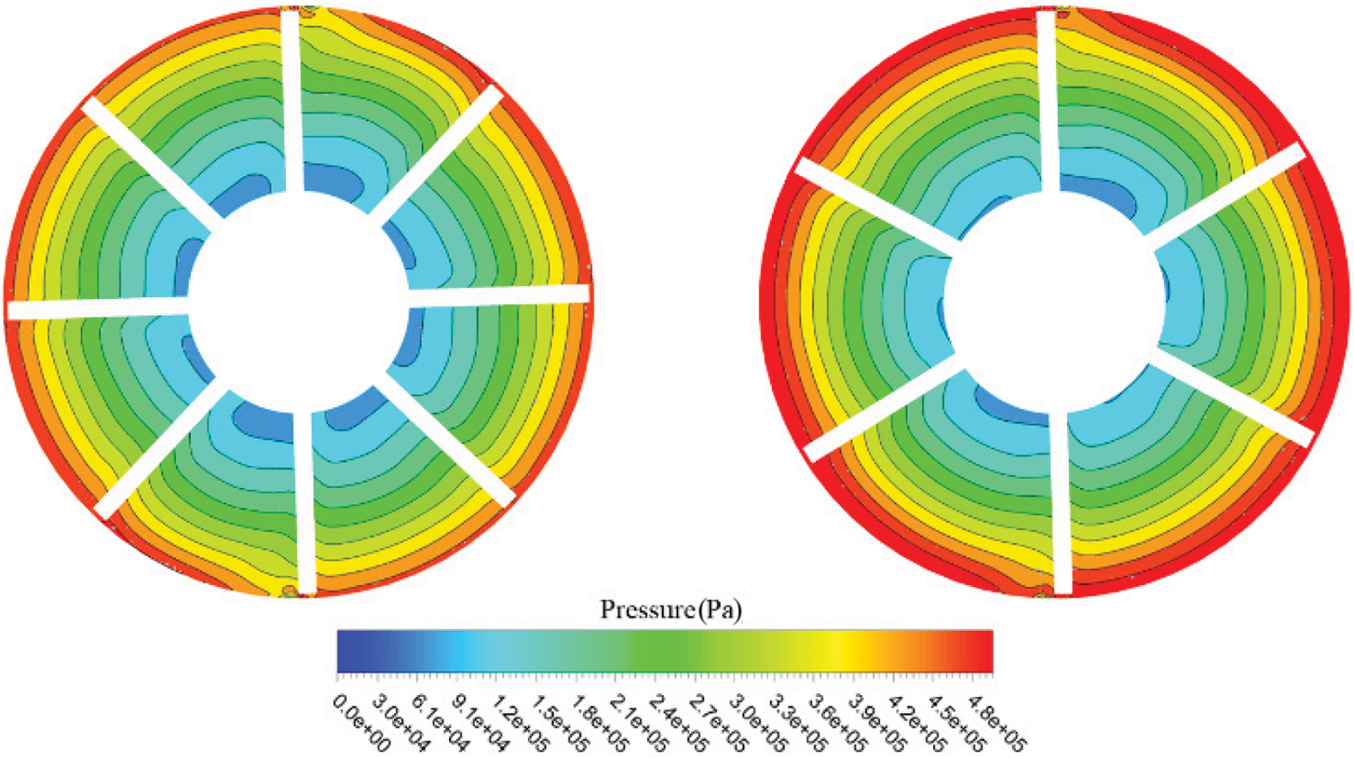
Figure 8: Comparison of pressure distribution before (left side) and after optimization
Increasing the pressure at the inlet improved the cavitation inside the pump. It can be seen from the two sets of pressure clouds that the pressure gradient at the inlet and outlet of the optimized impeller is significantly larger than that of the prototype pump. This indicates that the head of the optimized model is higher than that of the prototype pump, which is consistent with the conclusion that the head and efficiency of the optimized model are higher than those of the prototype pump obtained in this study.
5.3 Comparison of Streamline and Velocity Distribution
Fig. 9 shows the velocity distribution and internal fluid flow line distribution between the prototype pump and the impeller section of the optimized model. The fluid before entering the impeller and out of the impeller has the absolute velocity of zero non-rotating fluid. Owing to the rotation of the impeller and the inertia of the fluid, the relative motion between the impeller and the fluid, that is, the fluid in the impeller between the two blades, forms the direction of rotation and the opposite direction of rotation of the impeller vortex. The generation of this vortex is directly related to the finite number of blades, which decreases the degree of clamping of the blades to the fluid. Its vortex vector is parallel to the axis; thus, it is called an axial vortex.
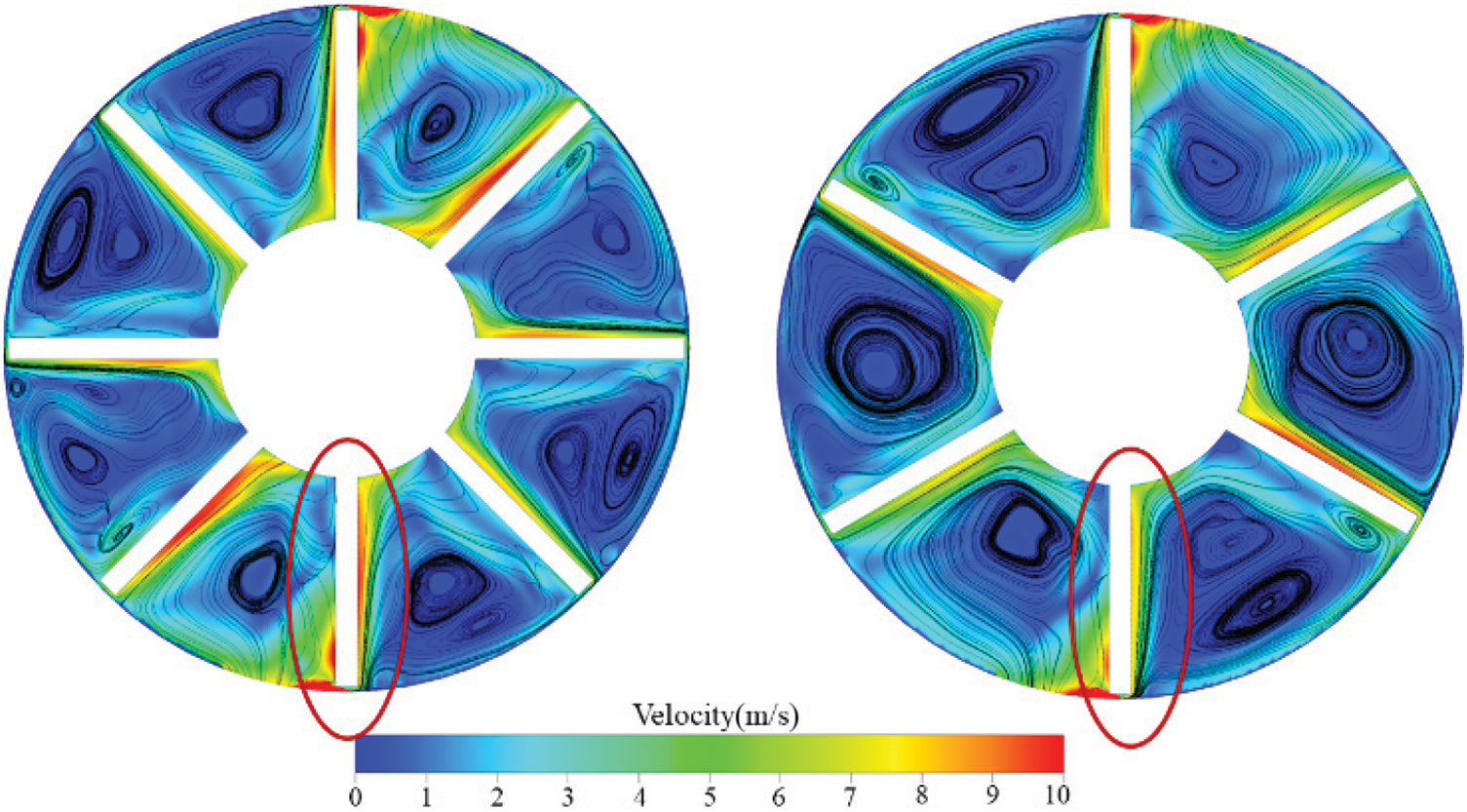
Figure 9: Comparison of streamline and speed distribution before (left side) and after optimization
The optimized model impeller blade number is less than that of the prototype pump, and the blade scale between the two impellers is slightly increased. However, the number of vortices in the pump is reduced, and the performance loss caused by the pump operation is reduced. The increase in the number of blades reduces the pump’s internal fluid flow range, and the static pressure conversion is insufficient to lead to a lower pump efficiency. Therefore, for the model selected in this study, the appropriate reduction in the number of blades positively impacts pump performance improvement.
The optimized model blade inclination angle is smaller than the prototype pump so that the fluid flow around the blade is less disturbed. We can see that the optimized model blade working surface flow line is more uniform and smoother distribution than the proto-type pump, resulting in less energy loss and improved pump efficiency. Combined with the velocity distribution cloud, the prototype pump within the blade around the fluid velocity is large. Moreover, the impact loss for the blade is relatively large, the optimization model blade around the velocity is small, and the gradient is small, implying that improving pump efficiency has a significant impact.
5.4 Comparison of Turbulent Kinetic Energy
The turbulent kinetic energy of the impeller cross-section under the rated conditions of the prototype pump and the optimized model are shown in Fig. 10. It can be seen that for the partial flow pump, turbulent energy mainly exists at the vane working surface, the impeller guide vane connection, and the impeller inlet. The larger the value of turbulent energy, the wider the distribution area, the greater the energy loss, and the greater the impact on the pump performance. According to the analysis of the internal flow field flow lines of the partial flow pump, the internal flow lines of the optimized model are more uniform and smoother than those of the prototype pump. The gradient of the internal fluid velocity distribution is small, and the velocity impact at the impeller blades is smaller. Thus, the turbulent kinetic energy distribution area of the optimized model is less than that of the prototype pump, and the turbulent kinetic energy intensity is lower, resulting in less energy loss. Thus, the efficiency of the optimized model is improved.
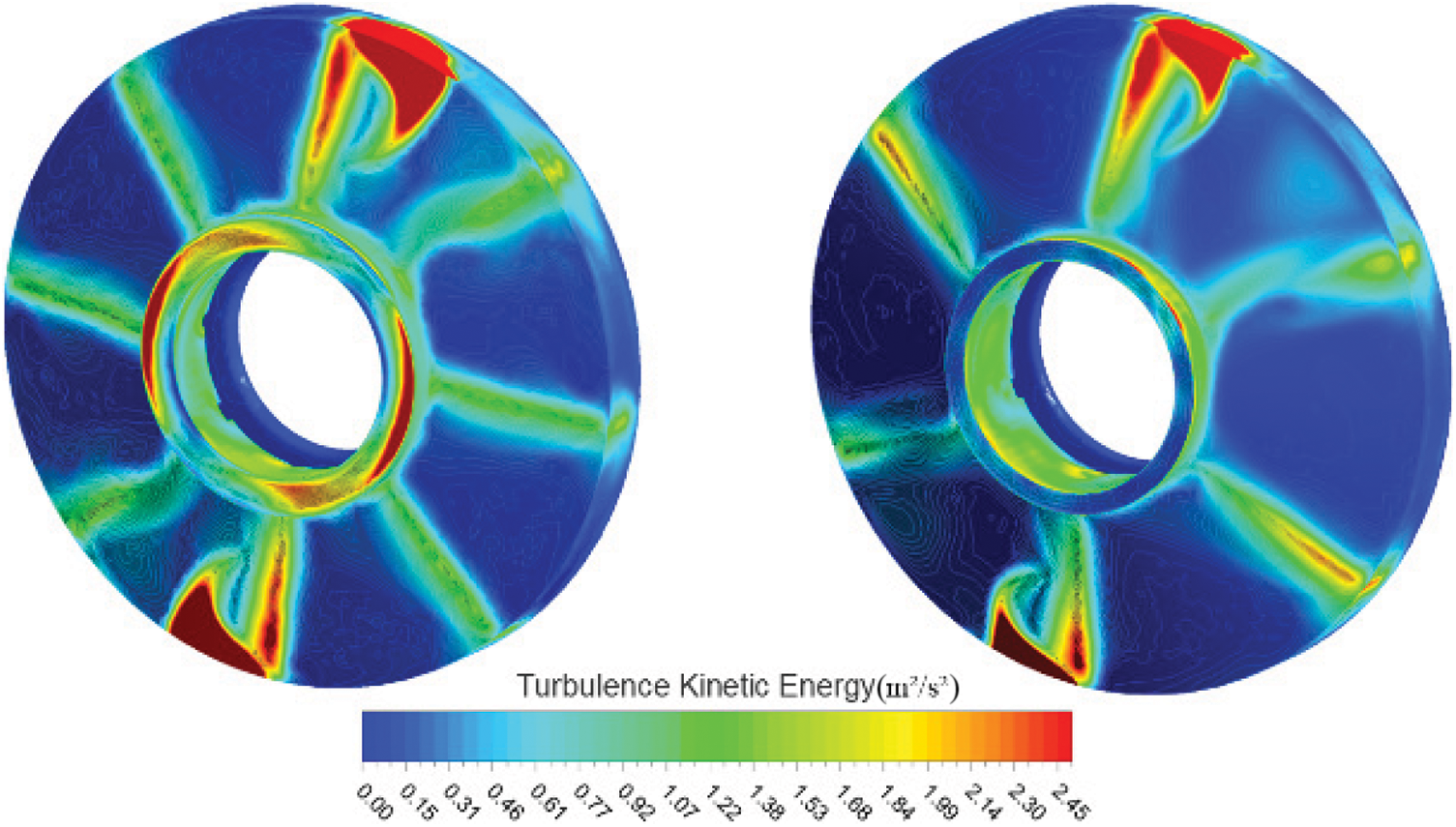
Figure 10: Comparison of turbulent kinetic energy distribution before (left side) and after optimization
In this study, the influence of each impeller geometry parameter on the performance of partial flow pumps was explored in detail by applying an orthogonal test method to the optimal design of high-speed partial flow pumps. Through the orthogonal test of nine groups of design solutions, the importance of the influence of 4 factors on the performance of a partial flow pump was analyzed. The influence of 4 factors on the performance of a partial flow pump was obtained. The following best combination of parameters was obtained to realize the optimal high-speed partial flow pump design: an impeller blade outlet width a = 2 mm, impeller inlet diameter b = 26 mm, blade inclination angle α = 70°, and number of blades z = 6.
The optimized model was obtained by modeling the optimal combination of parameters, and numerical simulations and post-processing of the optimized model were performed. The optimization results of the optimized model are validated by comparing the external characteristic curves, impeller pressure distribution, impeller internal flow and velocity distribution, and turbulent kinetic energy distribution of the original and optimized models. The efficiency η of the optimized model is improved by 12.11%, and the head H is increased by 23.5 m compared with that of the original model, which provides a reference for the subsequent structural optimization of partial flow pumps.
Acknowledgement: None.
Funding Statement: National Key R&D Program of China (Grant No. 2020YFC1512404).
Author Contributions: Conceptualization, J. W. and T. Y.; methodology, J. W. and Y. Z.; software, T. Y.; validation, J. W. and T. Y.; formal analysis, C. H.; investigation, T. Y.; resources, T. Y. and C. H.; data curation, T. Y.; writing original draft, T. Y.; writing—review and editing, J. W. and L. Z.; visualization, T. Y.; supervision, J. W. and Y. Z.; project administration, J. W. and L. Z.; funding acquisition, J. W. All authors have read and agreed to the published version of the manuscript.
Availability of Data and Materials: All data is presented in this research.
Conflicts of Interest: The authors declare that the research was conducted in the absence of any commercial or financial relationships that could be construed as a potential conflict of interest.
References
1. Shao, X., Zhao, W. (2019). Performance study on a partial emission cryogenic circulation pump with high head and small flow in various conditions. International Journal of Hydrogen Energy, 44(49), 27141–27150 (In Chinese). https://doi.org/10.1016/j.ijhydene.2019.08.181 [Google Scholar] [CrossRef]
2. Hosseini, S. E., Keshmiri, A. (2022). Experimental and numerical investigation of different geometrical parameters in a centrifugal blood pump. Research on Biomedical Engineering, 38(2), 423–437. https://doi.org/10.1007/s42600-021-00195-8 [Google Scholar] [CrossRef]
3. Mousmoulis, G., Kassanos, I., Aggidis, G., Anagnostopoulos, I. (2021). Numerical simulation of the performance of a centrifugal pump with a semi-open impeller under normal and cavitating conditions. Applied Mathematical Modelling, 89(3), 1814–1834. [Google Scholar]
4. Zeng, W. (2006). Design and experimental study of large flow part shunt pump and part shunt multistage pump (Master Thesis). Lanzhou University of Technology, China (In Chinese). [Google Scholar]
5. Shui, Q., Jiang, T., Pan, B., Yang, T., Pan, W. (2021). Numerical research on performance of high-speed partial emission pump. Shock and Vibration, 2021, 6697063. [Google Scholar]
6. Matlakala, M. E., Kallon, D. V. V., Mogapi, K. E., Mabelane, I. M., Makgopa, D. M. (2019). Influence of impeller diameter on the performance of centrifugal pumps. IOP Conference Series: Materials Science and Engineering, 655, 12009. https://doi.org/10.1088/1757-899X/655/1/012009 [Google Scholar] [CrossRef]
7. Boitel, G., Fedala, D., Myon, N. (2016). Tip clearance effects on loads and performances of semi-open impeller centrifugal pumps at different specific speeds. IOP Conference, 49(3), 032013. [Google Scholar]
8. Wang, Y., Yin, G., Wang, W. J. (2015). Numerical simulation of the internal flow field of a low specific revolution constant head pump. Journal of Drainage and Irrigation Machinery Engineering, 33(1), 6 (In Chinese). [Google Scholar]
9. Zhou, L., Shi, W., Bai, L., Lu, W., Li, W. (2014). Numerical calculation and experimental study of axial force in a deep-well centrifugal pump. Latin American Applied Research, 44(1), 105–110. https://doi.org/10.52292/j.laar.2014.426 [Google Scholar] [CrossRef]
10. Gopalakrishnan, S. (1999). Pump research and development: Past present and future—An American perspective. Journal of Fluids Engineering, 121(2), 237–247. https://doi.org/10.1115/1.2822197 [Google Scholar] [CrossRef]
11. Ueda, A., Takeda, T., Sugiyama, D., Miyagawa, K. (2022). Effect of the number of blades on diffuser unsteady loss of centrifugal pump. Journal of Physics: Conference Series, 2217, 12052. [Google Scholar]
12. Knyazeva, E. (2021). Design and fluid dynamics features of a low-flow high-head pump with barske-type impeller. E3S Web of Conferences, 320, 4013. https://doi.org/10.1051/e3sconf/202132004013 [Google Scholar] [CrossRef]
13. Lee, J., Kwon, Y., Lee, C. (2016). Design of partial emission type liquid nitrogen pump. Progress in Superconductivity & Cryogenics, 18(1), 64–68. https://doi.org/10.9714/psac.2016.18.1.064 [Google Scholar] [CrossRef]
14. Yu, Y. S. (2017). Tangential pump head coefficient and throat diameter characteristics analysis. Process Equipment & Piping, 54(5), 57–59 (In Chinese). [Google Scholar]
15. Li, Y., Shi, W. D., Wang, C. (2012). Experimental study of the effect of orifice plate on hump characteristics of high-speed partial emission pump. Energy Science and Research, 30(2), 45–50. [Google Scholar]
16. Yang, J., Wang, B., Zhang, X., Lin, S. (2017). The effect of throat area on tangential pump performance. Journal of Xihua University (Natural Science Edition), 36(5), 17–21 (In Chinese). [Google Scholar]
17. Yang, C., Wang, Q., Zhang, J. (2012). Study on the influence of geometric parameters of partial flow pump based on CFD technology on its performance. Journal of Xihua University (Natural Science Edition), 31(2), 62–65 (In Chinese). [Google Scholar]
18. Celik, I. B., Ghia, U., Roache, P. J., Freitas, C. J., Coleman, H. (2008). Procedure for estimation and reporting of uncertainty due to discretization in cfd applications. Journal of Fluids Engineering, 130(7), 78001. https://doi.org/10.1115/1.2960953 [Google Scholar] [CrossRef]
19. Chitrakar, S., Thapa, B. S., Dahlhaug, O. G., Neopane, H. P. (2017). Numerical and experimental study of the leakage flow in guide vanes with different hydrofoils. Journal of Computational Design and Engineering, 4(3), 218–230. https://doi.org/10.1016/j.jcde.2017.02.004 [Google Scholar] [CrossRef]
20. Ayad, A. F., Abdalla, H. M., Aly, E. A. (2015). Effect of semi-open impeller side clearance on the centrifugal pump performance using CFD. Aerospace Science & Technology, 47, 247–255. https://doi.org/10.1016/j.ast.2015.09.033 [Google Scholar] [CrossRef]
21. Peng, C. (2022). Influence of impeller type on internal flow of ultra-low specific speed centrifugal pump (Master Thesis). Xi’an University of Architecture and Technology, China (In Chinese). [Google Scholar]
22. Jafarzadeh, B., Hajari, A., Alishahi, M., Akbari, M. (2011). The flow simulation of a low-specific-speed high-speed centrifugal pump. Applied Mathematical Modelling, 35(1), 242–249. https://doi.org/10.1016/j.apm.2010.05.021 [Google Scholar] [CrossRef]
23. Wilcox, D. C. (2006). Turbulence modeling for CFD. CAN: DCW Industries. [Google Scholar]
24. Thakkar, S., Vala, H., Patel, V. K., Patel, R. (2021). Performance improvement of the sanitary centrifugal pump through an integrated approach based on response surface methodology, multi-objective optimization and CFD. Journal of the Brazilian Society of Mechanical Sciences and Engineering, 43(1), 1–15. [Google Scholar]
25. Gao, Z. J. (2016). Research on design method and smooth characteristics of magnetic drive centrifugal pump (Ph.D. Thesis). Jiangsu University, China (In Chinese). [Google Scholar]
Cite This Article
 Copyright © 2024 The Author(s). Published by Tech Science Press.
This work is licensed under a Creative Commons Attribution 4.0 International License , which permits unrestricted use, distribution, and reproduction in any medium, provided the original work is properly cited.
 Downloads
 Citation Tools