
 Submit a Paper
 Propose a Special lssue
 Open Access
ARTICLE

Structure Optimization of a Tesla Turbine Using an Organic Rankine Cycle Technology
1 School of Engineering, Shanghai Ocean University, Shanghai, 201306, China
2 Shanghai Marine Renewable Energy Engineering Technology Research Center, Shanghai, 201306, China
* Corresponding Author: Caiyin Xu. Email:
Fluid Dynamics & Materials Processing 2024, 20(6), 1251-1263. https://doi.org/10.32604/fdmp.2023.044804
Received 09 August 2023; Accepted 30 November 2023; Issue published 27 June 2024
 View Full Text
 Download PDF
Abstract
The so-called ORC (Organic Rankine Cycle) heat recovery technology has attracted much attention with regard to medium and low temperature waste heat recovery. In the present study, it is applied to a Tesla turbine. At the same time, the effects of the disc speed, diameter and inter-disc gap on the internal flow field and output power of the turbine are also investigated by means of CFD (Computational Fluid Dynamics) numerical simulation, by which the pressure, velocity, and output efficiency of the internal flow field are obtained under different internal and external conditions. The highest efficiency (66.4%) is obtained for a number of nozzles equal to 4, a disk thickness of 1 mm, and a gap of 1 mm between the disks. The results of the study serve as a theoretical basis for the structural design and optimization of Tesla turbines.Keywords
The Tesla turbine was invented and patented by Nikola Tesla in 1913. Some recent advances can be found at https://doi.org/10.1016/j.applThermaleng.2022.118141 [1], but did not lead to industrial development after the introduction of the patent in 1913. Due to the recent emergence of ORC organic rankine cycle system and the popularity of distributed power generation, the scientific research on the use of Tesla turbines in this small-scale recycling system is very valuable, and therefore has received widespread attention and research by researchers in Shanghai, China.
As an important output component of the ORC waste heat recovery system, the structure and performance of the expander have a great impact on the power generation efficiency of the system. The current axial flow radial or axial turbine expanders of ORC systems often fail to meet the requirements of high efficiency, reliability, compactness and low cost. Therefore, it is necessary to study and analyze the design of turbines in ORC systems.
Polish and other scholars have conducted research on the application of Tesla turbines under low loads: Lampart et al. [2] applied a Tesla turbine in a co-generation micro power unit to explore its feasibility. Hasan [3] investigated the possibility of applying a Tesla turbine instead of an air conditioning compressor in an automotive system, where the energy transfer process uses a chain to connect the turbine rotor disc to the automotive engine bearings.
In the 1960s, Rice [4] developed a well-established analytical/numerical model in the Tesla turbine and performed a series of experimental studies to demonstrate that the Tesla turbine could be the leading technology for small micropower applications. Later, Rice further investigated the turbine by performing experimental analysis of six different configurations of the Tesla turbine and developing an analytical model for the flow within the rotor disk. Cirincione [5] developed a Tesla hybrid turbine using r245fa; the authors reported isentropic efficiency values exceeding 70% when using steam as the working fluid. Bao et al. [6] presented a computational model for evaluating the flow inside a Tesla turbine that works with a variety of organic work fluids; one of the main achievements is the verification that the best performance of the turbine is achieved for very thin gap widths and fluids with high kinematic viscosity.
Carey [7] improved the model developed by Rice and coupled it to a small-scale Rankine cycle system. Lemma et al. [8] performed a campaign throughout the calculations and experiments, emphasizing that the efficiency was mainly hindered by viscous losses. Choon et al. [9] used the potential energy of tap water to convert the potential energy into electrical energy during the storage of water, resulting in a hydro cycle to generate electricity. Hoya et al. [10] used the hydrostatic pressure loss to determine the efficiency of the supply nozzle. The friction coefficient (indicating the energy loss associated with friction) of a Tesla turbine is 10 times higher than that of a gas turbine. Ji et al. [11] introduced a small-scale WHR (Waste Heat Recovery) scheme that uses a Tesla turbine to convert waste heat into mechanical energy, which in turn outputs electrical energy. A combined WHR system was designed to verify the feasibility of the scheme.
The Tesla turbine is a very unique type of turbine, which is bladeless and consists of a series of parallel flat discs that transfer work using fluid viscous effects as well as friction, which are assembled coaxially with a tiny gap between each disc. Since the fluid needs to flow into the rotor as much as possible, the bladeless rotor is positioned in a frame with one or more nozzles, causing the fluid to enter the system circumferentially [12].
The Tesla turbine differs from the conventional vane turbine in that it works by exploiting the boundary layer effect of the fluid: when the fluid flows around a solid wall and the motion is turbulent, the viscous forces are very small and negligible; however, the viscous forces are large in the thin layer close to the wall [13–15]. Due to this viscous force and the friction between the fluid and the disc makes a considerable velocity gradient along the wall in the normal direction, the thin layer near the wall is called the boundary layer. The thickness of the boundary layer is determined by the Reynolds number. The larger the Reynolds number of the fluid working medium, the thinner the boundary layer [16].
The transition from the flow within the boundary layer to the external flow velocity is gradual, and the closer to the wall, the smaller the flow velocity. Depending on the magnitude of the Reynolds number, the flow within the boundary layer has both laminar and turbulent forms [15,17]. The following figure shows the schematic diagram of a fluid using the boundary layer effect to drive the rotation of a Tesla turbine disc. The principle of operation is based on the boundary layer effect in fluid dynamics. When a fluid (e.g., a gas or a liquid) flows on the surface of an object (e.g., a pipe wall or a turbine blade), due to viscous forces, the fluid forms a very thin boundary layer at the edge of the object. Within the boundary layer, the flow velocity is zero at a fixed surface, and the velocity increases the farther away from the surface. In the Tesla turbine, this principle is utilized to achieve effective guidance and utilization of the fluid within the boundary layer by means of a carefully designed turbine blade shape and layout. Specifically, the special shape of the turbine blades can make the fluid flowing through the surface of the blades form a specific velocity distribution within the boundary layer, thus realizing efficient energy conversion.
An example of a rotor disc is shown in the Fig. 1 above. The fluid viscosity causes momentum to diffuse from the fluid to the disc, and the momentum of the working fluid is converted into kinetic energy for the rotation of the disc. The working medium enters the rotor from the outer edge of the turbine disc, and the first fluid layer adheres to the disc surface by adhesion forces. Particles from the high-speed fluid layer collide with particles from the low-speed fluid layer and generate momentum exchange. As a result, momentum is transferred to the first fluid layer in contact with the disc and the rotor starts to rotate. It was shown [12] that the Tesla turbine is very suitable for small ORC systems and ideally, its power generation efficiency can be as high as 80%.
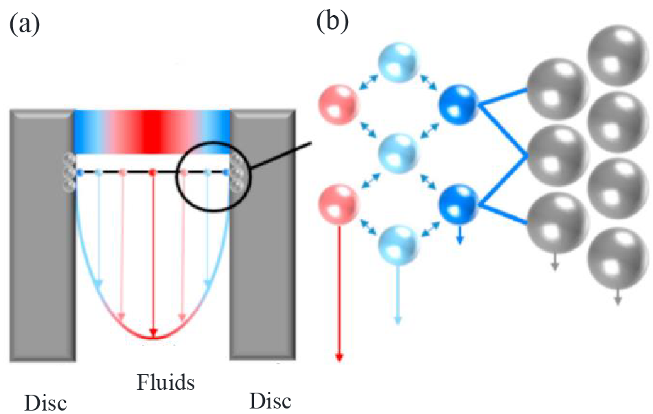
Figure 1: Tesla turbine operating principle (a) velocity distribution between discs; (b) adhesion force and momentum transfer [18]
Specific optimization of the Tesla turbine structural parameters such as disc speed, inter-disc clearance and external environment [12] was carried out to derive a series of internal structural parameters of the disc to improve the performance and efficiency of the Tesla turbine as a way to improve the efficiency of practical applications. The special structure and applicable scenarios of the Tesla turbine are used to replace the conventional expander in the ORC system, thus improving the power generation efficiency and simplifying the structure manufacturing process. The feasibility and efficiency of the Tesla turbine for ORC system will be investigated through simulation to discover the maximum efficiency of the Tesla turbine for ORC power generation system.
2 Mathematical Model for Fluid Simulation
Numerical simulations were performed using Ansys 2021 commercial software. Since there is a considerable variation in the flow temperature between the discs, its effect on the laminar flow viscosity values needs to be considered. Considering the change in laminar fluid viscosity due to temperature variation may affect the shear stresses generated on the valve disc walls. The methodology of this study uses the Sutherland’s formula for its modeling, which is widely used in engineering because it describes more accurately the variation of fluid viscosity with temperature. This formula is derived based on experimental data and has a simple form that is easy to implement in calculations. In the numerical simulation of disc valves, the effect of viscosity on shear stresses needs to be considered because changes in flow temperature may lead to changes in fluid viscosity. Based on this, the use of Sutherland’s formula can be used to calculate the fluid viscosity at different temperatures in a very good way, thus simulating more accurately the flow inside the disc valve.
By using Sutherland’s Eq. (1) to determine
where
where Sutherland temperature
The turbulence model used for the simulation is k-ωSST, which is a combined model of the near-wall k-ω turbulence model and the far-field k-ε turbulence model. The surface roughness is modeled using the sand roughness ε. can be derived using the arithmetic mean deviation of the roughness height Ra:
The calculations were performed in Ansys Fluent, which uses an implicit finite volume format for the model. Since the simulation experiment fluid is set to be an incompressible gas, in the experiment it is only affected by the viscosity according to Eq. (1), so the density does not change. Its formula is as Eq. (3), and the mass, momentum and energy conservation solution equations are as follows:
where ρ is the density, t is the time, and u is the velocity vector.
where g is the gravitational acceleration,
where μ is the dynamic viscosity,
where E is the total energy, q is the heat flux, λ is the thermal conductivity, T is the temperature.
The conservation equation is the Reynolds mean equation, the turbulent stress is modeled using the Boussinesq assumption, and the turbulent viscosity is assumed to be determined using a stochastic turbulence model [19,20].
In order to summarize the results of the numerical simulation, the torque is calculated using the integral of the tangential stress on the disc surface, which is in turn based on dynamic viscosity, eddy viscosity and velocity gradient. n is the system power in KW and the expression is as follows:
The turbine efficiency is calculated as follows:
where
3 Numerical Simulation Process
The model is divided into two parts, the stator and the rotor. The stator housing and the disk gap area are fixed without slippage, but the rotor disk and the bottom wall of the inter-disk gap in contact with the disk are rotated, and the area is set as a rotational degree of freedom dynamic grid area. The initial model shell diameter is 115 mm, a rectangular nozzle inlet is distributed circumferentially, the nozzle is tangential along the circumference at an angle of 15°, and the length is 30 mm. the internal disc outer diameter is 100 mm, the inter-disc gap is 1 mm, the disc thickness is 1 mm, the mass of the disc is 0.3537 kg, and the rotational inertia is 0.042 kg/m2. The discs are assembled coaxially and distributed circumferentially and side-by-side in the turbine inner measurement, as shown in Fig. 2:
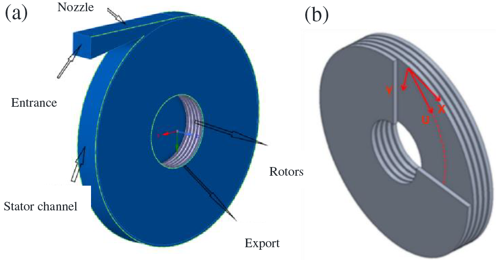
Figure 2: Tesla turbine (a) 3D model design; (b) Rotor disc model
The shape of the Tesla turbine is divided into two regions: the stator and the rotor. The rotor region is composed of five discs coaxially and arranged side by side, and the turbine as a whole is symmetrically distributed about the middle plane perpendicular to the rotation axis. The nozzle is located in the outer edge region of the turbine stator, and the fluid incidence direction is inclined at an angle of 15° from the circumferential tangential direction. In this paper, the mathematical model of the Tesla turbine rotor is modified to adapt it to the actual power generation system operation. The model is first validated by comparison with other literature models. The optimal choice of rotor geometry is then investigated by parametric analysis of the basic design parameters. The rotor efficiency depends on the structural parameters of the disc, especially the clearance and exit diameter, which largely determine the kinetic energy release during operation.
In order to obtain very reliable simulation results without increasing the computational cost and difficulty, it is necessary to find the optimal grid size for specific conditions and perform grid dependence tests. The actual results are predicted using the Richardson extrapolation method, and then the error is applied to that actual value and the element size is determined based on that error. The element size used is 1 × 10⁻³ m. The grid model is shown in Fig. 3.
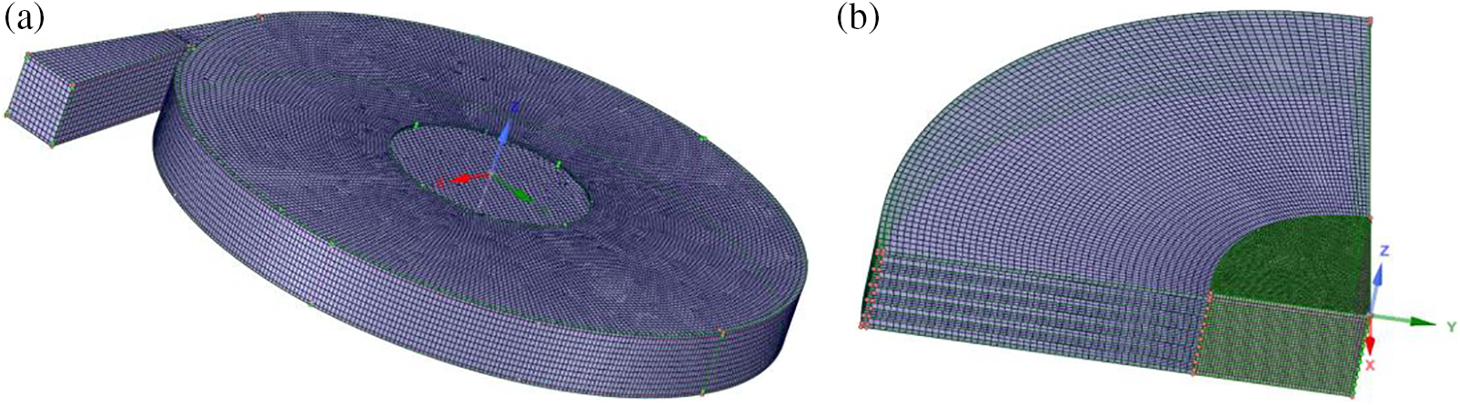
Figure 3: Turbine stator and rotor mesh division (a) stator; (b) rotor
Spaceclaim is a drawing and meshing software that comes with Ansys Workbench platform, whose main functions are 2D and 3D collection drawing, meshing and export, etc. All meshes are drawn using spaceclaim software in ANSYS.
The results of the grid-independence study are shown in Fig. 4, where the greater the sealing of the grid, the greater the output torque when the inlet flow is fixed. When the grid number reaches 1.6 million, the increase of grid number has no effect on the output torque. So the grid number in this paper is set to 1.6 million. n is the system power, and the magnitude of the power N can be used as an index to characterize the quality of the grid because it is calculated based on thermodynamic and kinematic parameters in KW, and the expression is as follows:
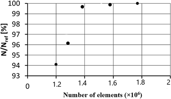
Figure 4: Grid independence analysis of Tesla turbine model
The reference power is
3.3 Numerical Simulation Boundary Conditions
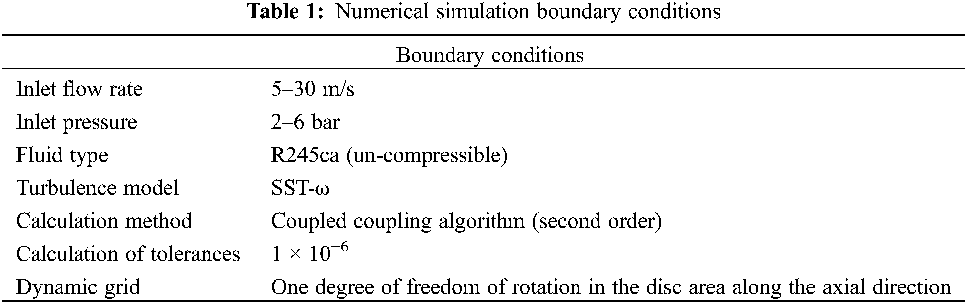
During turbine operation, laminar and turbulent flows coexist in the vortex disk, However, the laminar flow predominantly occurs within the fluid region between two disks, a turbulence model can be employed to approximate the calculation. For nozzle inlet pressure given as 2–6 bar, considering the boundary layer movement and pressure loss, all the stator and rotor surfaces of the turbine are set as fixed non-slip wall surfaces, and the wall surface of the rotor disc and the rotor shaft are given as rotating moving wall surfaces along the axial direction. As such, the disk region was configured as a dynamic grid featuring single degree of passive rotation. The heat transfer coefficient is 2 W/m2 K. The ambient temperature is set to 25°C, the turbulence intensity of the working medium is 5.0% and the turbulent dissipation rate is 10.0%.
For the working fluid, R245ca was finally selected as the organic circulating work fluid under comprehensive consideration. Since the work fluid library under FLuent software does not contain R245ca, the simulations in this paper are all calculated using the standard incompressible ideal gas model in the software. During pre-processing, the gas was redefined with various physical parameters such as R245ca.
The pressure-based solver was selected based on the solution results. A coupled scheme was adopted due to its suitability for simulating high-speed flowing fluids and solving multi-physical problems, such as flow and heat transfer simultaneously. Other parameters, such as the second-order upwind format of momentum, were kept at their default settings. The time step size was determined through numerous computational attempts, considering the balance between solving speed and accuracy.
The following Table 1 shows the initial ranges and values given by the boundary conditions:
3.4 Determination of iNlet Flow Rate and Inlet Pressure
The established model was simulated numerically using the control variables method in sequence, given a rotor disc region with a dof rotational degree of freedom along the axial direction, a rotor mass of 0.3537 kg, and a rotational inertia of 0.0418 kg•m2, all of which can be obtained from Spaceclaim in Ansys. The disc wall was set as the dynamic grid area, and the relationship between disc speed and power and efficiency of the Tesla turbine was examined at different nozzle inlet initial pressures of 2–6 bar, and the data were collected several times, respectively, and the following results were obtained. The disc speed is converted by detecting the maximum linear velocity of the disc wall, and the power is calculated by Eq. (5) above. Fig. 5 shows the relationship between disc speed and turbine power at different inlet initial pressures.
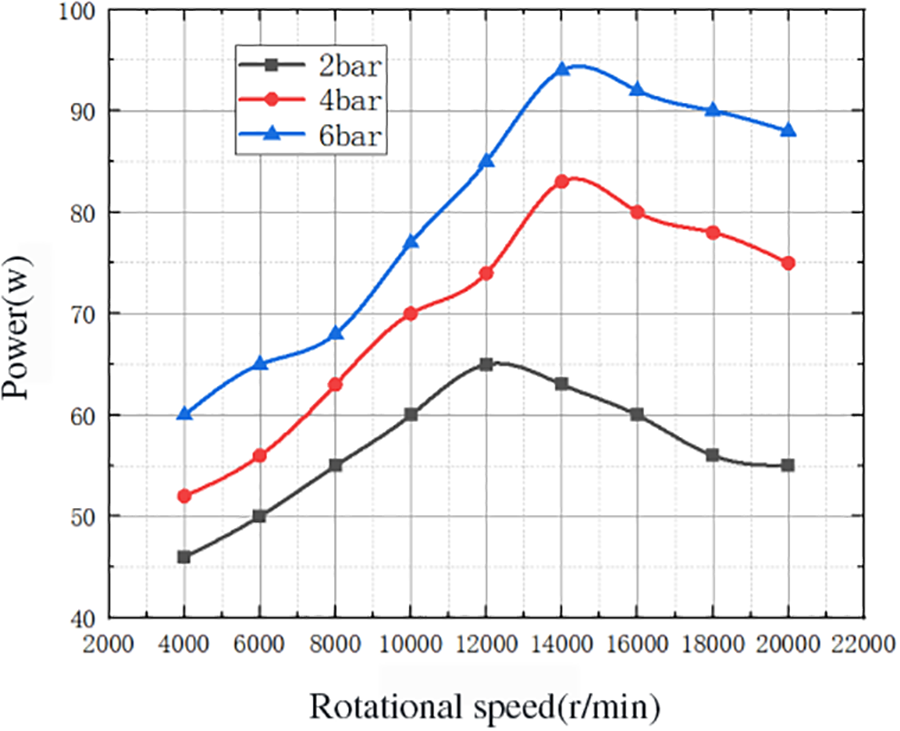
Figure 5: Relationship between disc speed and turbine power under different inlet pressures
As can be seen from Fig. 5, overall the inlet pressure has a certain degree of influence on the disc speed and turbine power, and the influence on the power is more obvious, and the power increases with the increase of the initial pressure. When the nozzle inlet pressure is 6 bar and the disc rotation speed is 14000 r/min, the highest power is obtained, which is about 95 W.
The power in the numerical study was calculated from the average power values at each time step of the transient simulation [21,22]. All features of the power curve are parabolic in shape and relatively flat, which indicates that the power does not vary much over a wide range of rotational speeds. Therefore, the effect on the turbine power is not significant when the speed is increased to a certain level, and the higher the speed, the higher the energy loss caused to the system and the lower the disc torque. Through the flow rate of 5, 10, 15, 20, 2, 30 m/s fluid in and out of the inlet and outlet pressures of 1 × 10⁵ Pa to 1 × 10⁷ Pa, respectively, the control variable analysis, the final inlet flow rate is set to 20 m/s, the fluid inlet and outlet pressures of 6 × 10⁵ Pa.
4 Analysis of the Influence of Turbine Structure Parameters
4.1 Effect of Disk Thickness and Inter-Disk Gap on Turbine Efficiency
In order to study the effect of the Tesla turbine disc on its working efficiency, numerical simulation experiments were conducted using the single nozzle Tesla turbine model established in the previous section from the two perspectives of disc thickness as well as inter-disc clearance, with an inlet initial velocity of 10 m/s, an inlet pressure of 6 x 10⁵ Pa and a working fluid of R245ca. Fig. 6 below shows the simulation results of efficiency (η) vs. disc spacing recording. The test data and its efficiency was calculated using the above empirical formula.
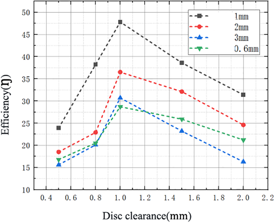
Figure 6: Effect of different disc thickness and disc clearance on efficiency
It can be seen that the overall efficiency value is in the range of 15.6% to 47.8%, with a parabolic distribution, and the highest efficiency value of 47.8% occurs when the disc thickness is 1 mm and the clearance between discs is 1 mm. It is worth noting that the turbine efficiency does not increase linearly with the increase of the gap, so it can be concluded that the disc gap should neither be too large nor too small, and there is an optimal value within a certain range. If the disc spacing is too small, the fluid will not enter this space due to viscous forces. On the other hand, when the disc spacing is too large, the fluid loses adhesion and its kinetic energy is not well transferred to the rotor. Different disc spacing allows for different flow patterns, and in general, the efficiency parameter is strongly influenced by the velocity.
Also, the disc thickness should be taken within a certain range. When the disc thickness is 1 mm, the turbine efficiency on each inter-disc gap is higher than other disc thickness sizes. It can be inferred from this that if the thickness of the disc is too large, the air flow into the disc channel will be more difficult, so the pneumatic performance becomes poor. However, the disc thickness cannot be too small, mainly limited to its mechanical stress and processing problems. As the thickness of the disc decreases, the stiffness of the disc decreases rapidly, so the mechanical stress increases, which should be lower than the allowable stress of the material.
4.2 Effect of Nozzle on Turbine Efficiency
The nozzle is one of the most important components of the Tesla turbine, and changes in its number and structure are significant for the internal fluid flow conditions and rotor speed variations, thus affecting the efficiency of the whole turbine. Phenomena such as shock waves, over-expansion or over-compression are the main causes of nozzle efficiency degradation [19,20]. Fig. 7 below shows the working fluid velocity distribution profile of the Tesla turbine when the inlet initial velocity is 20 m/s, other parameters are the same, and the number of nozzles is 1, 2, and 4, respectively.
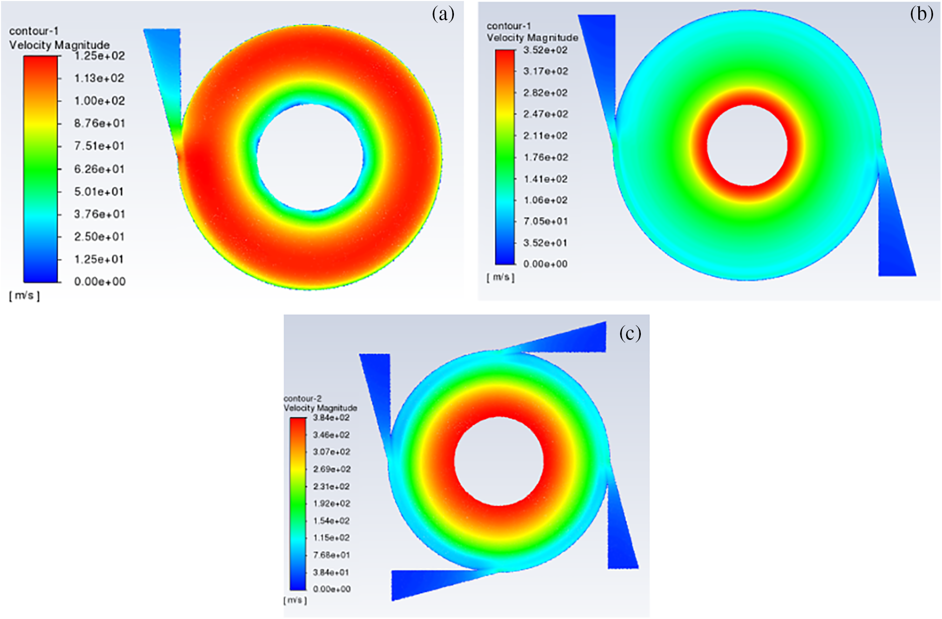
Figure 7: Turbine internal velocity distribution profile with different number of nozzles (a) single nozzle; (b) double nozzle; (c) four nozzles
When other conditions remain the same, only change the number of Tesla turbine nozzles, the velocity distribution cloud shown above, the pressure distribution cloud shown in Fig. 8. From the nozzle inlet to the turbine outlet, the fluid flow velocity increases in the radial direction, but the pressure decreases in the radial direction. The effect of the axisymmetric distribution of the rotor on the turbine efficiency was verified by varying the number of nozzles, thus affecting the uniformity of the fluid injection and the inflow. The results show that as the number of nozzles increases from 1 to 4, the overall velocity-pressure distribution values show an increasing trend and the peak efficiency increases continuously, with the maximum value occurring at lower speeds.
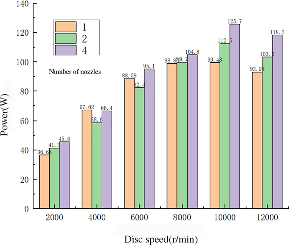
Figure 8: The relationship between disc rotation speed and power under different number of nozzles
In order to study the effect of the number of nozzles on the power generation efficiency of Tesla turbine, the turbine with the number of nozzles 1, 2 and 4 was tested with the inlet speed of 20 m/s, inlet pressure of 6 × 10⁵ Pa and other variables kept consistent, and Figs. 8 and 9 show the relationship between disc speed and power and efficiency for different number of nozzles obtained after the experiment, respectively.
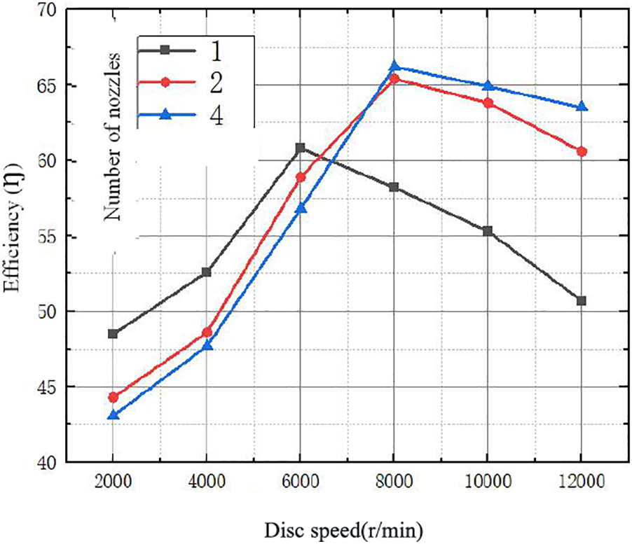
Figure 9: Relationship between disc speed and efficiency for different number of nozzles
It was found that the system power all increased to some extent with the increase of the number of nozzles, and in general with the increase of the number of nozzles. When the disc speed is 10000 r/min, the four-nozzle Tesla turbine can produce 125.7 W of power. But the efficiency of the work only in the low speed range has a large increase, and its efficiency gradually decreases at higher speeds. The more nozzles there are, the greater the loss at the nozzle. The four-nozzle turbine can achieve 66.4% efficiency at a speed of 8000 r/min. In addition, readers may be interested in what happens with more than 4 nozzles. For relevant research on more than four nozzles, you can find it at “https://pubs.aip.org/aip/pof/article/29/9/9/093604/966735/The-fluid-dynamics-of-symmetry-and-momentum” [23].
Therefore, in the low rpm range, the mechanical efficiency of the Tesla turbine decreases as the number of nozzles increases. In the high speed range, the mechanical efficiency of the Tesla turbine increases with the increase in the number of nozzles. The reason for this analysis is that in the high speed range, part of the flow rate is less than the disc speed, thus creating a resistance that gradually reduces the mechanical efficiency. However, more nozzles lead to a higher flow rate, which slows down the velocity difference between the fluid and the disc and can prevent the mechanical efficiency of the Tesla turbine from decreasing. Therefore, while increasing the number of turbine nozzles, the disc speed should be controlled within the appropriate range so that the flow rate and losses generated by it can be balanced and thus the efficiency can be improved to a certain extent.
The external environmental impact analysis and the internal mechanical structure parameter optimization, as well as the output performance simulation study, were conducted on the turbine, the key component of the thermal power conversion in the medium and low-temperature waste heat recovery system, and the Tesla turbine was applied as the turbine expander in this ORC waste heat recovery system to achieve the power and efficiency of the whole device under the given conditions. The power and efficiency of the whole unit are improved under the given conditions. The design optimization of the internal structural parameters of the Tesla turbine was carried out through 3D modeling by Solidworks and numerical simulation by Ansys workbench, and the main work contents and results are as follows:
(1) A three-dimensional model of the Tesla turbine was designed for the ORC waste heat recovery system, and the working principle of the Tesla turbine, and its structural parameters were optimized. Then, the established 3D model was meshed and pre-processed by numerical simulation software Ansys, and the optimized model was verified by the simulation results, which showed that the fluid flow state and velocity-pressure distribution inside the Tesla turbine were relatively uniform and the overall performance was good. The simulation results were compared to verify the rationality and correctness of the model design.
(2) Combined with the mathematical model calculation method and Ansys Fluent numerical simulation, the internal structural parameters affecting the efficiency of the Tesla turbine were analyzed in turn, and several parts and parameters that have a great influence on the efficiency of the turbine were selected. A detailed study was conducted to analyze the effects and causes of each internal parameter variable. The single variable is investigated using the control variables method, and the values of each internal structure parameter are obtained for optimal turbine efficiency by combining mathematical models and Fluent software simulation validation.
In this paper, the Tesla turbine is introduced into the ORC waste heat recovery system to replace the conventional vane-type expander for power generation, and its external operating environment, as well as internal structural parameters, are designed and optimized, resulting in a maximum efficiency of 66.4% with 4 nozzles, 1 mm disk thickness and 1 mm inter-disk gap, resulting in an average 0.3% increase in output power as well as efficiency.
Acknowledgement: None.
Funding Statement: The authors would like to express their gratitude for the support by the National Natural Science Foundation of China (No. 51876114), and Shanghai Engineering Research Center of Marine Renewable Energy (Grant No. 19DZ2254800).
Author Contributions: The authors confirm contribution to the paper as follows: study conception and design: Yongguo Li, Dingjian Zheng; data collection: Caiyin Xu; analysis and interpretation of results: Caiyin Xu; draft manuscript preparation: Caiyin Xu, Can Qin. All authors reviewed the results and approved the final version of the manuscript.
Availability of Data and Materials: Our data is calculated by ourselves. After the paper is published, we will make the research data public for researchers to use.
Conflicts of Interest: The authors declare that they have no conflicts of interest to report regarding the present study.
References
1. Ganguly, A., Sengupta, S., Pramanik, S. (2022). Waste heat recovery using Tesla turbines in Rankine cycle power plants: Thermofluid dynamic characterization, performance assessment and exergy analysis. Applied Thermal Engineering, 207, 118141. https://doi.org/10.1016/j.applthermaleng.2022.118141 [Google Scholar] [CrossRef]
2. Lampart, P., Kosowski, K., Piwowarski, M., Jędrzejewski, Ł. (2009). Design analysis of Tesla micro-turbine operating on a low-boiling medium. Polish Maritime Research, 16, 28–33. [Google Scholar]
3. Hasan, A. M. (2016). Investigating the possibility of using a Tesla turbine as a drive unit for an automotive air-conditioning compressor using CFD modeling. ASHRAE Transactions, 122(1), 146–160. [Google Scholar]
4. Hasinger, S. H., Kehrt, L. G. (1965). Discussion: An analytical and experimental investigation of multiple-disk turbines. Journal of Engineering for Power, 87(1), 36. https://doi.org/10.1115/1.3678136 [Google Scholar] [CrossRef]
5. Cirincione, N. (2011). Design, construction and commissioning of an organic rankine cycle waste heat recovery system with a tesla-hybrid turbine expander (Dissertations & Theses). Gradworks. [Google Scholar]
6. Bao, G., Shi, Y., Cai, N. (2013). Numerical modeling research on the boundary layer turbine using organic working fluid. Proceedings of the International Conference on Power Engineering-13 (ICOPE-13), pp. 24–27. Castellon, Valencia Region, Spain. [Google Scholar]
7. Carey, V. P. (2010). Assessment of Tesla turbine performance for small scale rankine combined heat and power systems. Journal of Engineering for Gas Turbines and Power, 132(12), 122301. https://doi.org/10.1115/1.4001356 [Google Scholar] [CrossRef]
8. Lemma, E., Deam, R. T., Toncich, D., Collins, R. (2008). Characterisation of a small viscous flow turbine. Experimental Thermal and Fluid Science, 33(1), 96–105. https://doi.org/10.1016/j.expthermflusci.2008.07.009 [Google Scholar] [CrossRef]
9. Choon, T. W., Rahman, A. A., Jer, F. S., Aik, L. E. (2011). Optimization of Tesla turbine using computational fluid dynamics approach. 2011 IEEE Symposium on Industrial Electronics and Applications, pp. 477–480. Langkawi, Malaysia. [Google Scholar]
10. Hoya, G. P., Guha, A. (2009). The design of a test rig and study of the performance and efficiency of a tesla disc turbine. Proceedings of the Institution of Mechanical Engineers, Part A: Journal of Power and Energy, 223(4), 451–465. [Google Scholar]
11. Ji, F., Bao, Y., Zhou, Y., Du, F., Zhu, H. et al. (2019). Investigation on performance and implementation of tesla turbine in engine waste heat recovery. Energy Conversion and Management, 179, 326–338. https://doi.org/10.1016/j.enconman.2018.10.071 [Google Scholar] [CrossRef]
12. Li, Y. G., Du, J., Zheng, D. J. (2021). A review of Tesla turbine operational performance studies. World Technology Research and Development, 43(6), 649–663. [Google Scholar]
13. Hadi, F., Yang, H., Traum, M. J. (2021). Assessment of performance of Tesla turbine in water distribution systems for energy harvesting. Journal of Energy Resources Technology, 143(4), 042101. https://doi.org/10.1115/1.4048018 [Google Scholar] [CrossRef]
14. Rusin, K., Wróblewski, W., Strozik, M. (2019). Comparison of methods for the determination of Tesla turbine performance. Journal of Theoretical and Applied Mechanics, 1(1), 563–575. [Google Scholar]
15. Sivaramakrishnaiah, M., Reddy, Y. S. K., Reddy, G. S. (2017). Study and design of bladeless Tesla turbine. International Journal of Theoretical and Applied Mechanics, 12(5), 881–889. [Google Scholar]
16. Fu, X. L. (2008). Theoretical analysis and experimental research on the combustion characteristics of homogeneous charge compression ignition (HCCI) of micro engines (Doctoral Dissertation). Chongqing University, China. [Google Scholar]
17. Wu, K., Zhe, Y., Zhu, L., Zhan, W. L., Liu, Q. H. (2014). Thoughts on establishing a metallurgical reaction engineering discipline system. Journal of Iron and Steel Research, 26(12), 8 (In Chinese). [Google Scholar]
18. Rusin, K., Wróblewski, W., Rulik, S. (2021). Efficiency based optimization of a Tesla turbine. Energy, 236, 121448. https://doi.org/10.1016/j.energy.2021.121448 [Google Scholar] [CrossRef]
19. Ghasemi, S. E., Ranjbar, A. A. (2017). Numerical thermal study on effect of porous rings on performance of solar parabolic trough collector. Applied Thermal Engineering, 118, 807–816. https://doi.org/10.1016/j.applthermaleng.2017.03.021 [Google Scholar] [CrossRef]
20. Li, Z. T. (2019). Aerodynamic optimization design and performance analysis of small ORC axial-flow turbine (Doctoral Dissertation). Huazhong University of Science and Technology, China. [Google Scholar]
21. Hoque, A., Saki, M. E., Mehedi, T., Islam, S. H. T., Islam, M. et al. (2021). Design and development of a small-capacity Tesla turbine for rural applications. 2nd International Seminar of Science and Applied Technology (ISSAT 2021), pp. 362–368. Bandung, Indonesian, Atlantis Press. [Google Scholar]
22. Nemanic, A. C., Gaikwad, D. S., Garcia, S., Weiss, H. L., Traum, M. J. (2022). A Tesla turbine & prony brake dynamometer kit for remote benchtop gas turbine educational experimentation. AIAA SCITECH 2022 Forum, California, USA. [Google Scholar]
23. Sengupta, S., Guha, A. (2017). The fluid dynamics of symmetry and momentum transfer in microchannels within co-rotating discs with discrete multiple inflows. Physics of Fluids, 29(9), 093604. https://doi.org/10.1063/1.5001252 [Google Scholar] [CrossRef]
Cite This Article
 Copyright © 2024 The Author(s). Published by Tech Science Press.
This work is licensed under a Creative Commons Attribution 4.0 International License , which permits unrestricted use, distribution, and reproduction in any medium, provided the original work is properly cited.
 Downloads
 Citation Tools