
 Submit a Paper
 Propose a Special lssue
 Open Access
ARTICLE

Effects of Temperature and Liquid Nitrogen (LN2) on Coal’s Mechanical and Acoustic Emission (AE) Properties
1 Inner Mongolia Research Institute, China University of Mining and Technology-Beijing, Ordos, 017001, China
2 Beijing Key Laboratory for Precise Mining of Intergrown Energy and Resources, China University of Mining and Technology-Beijing, Beijing, 100083, China
3 School of Civil Engineering and Architecture, Xi’an University of Technology, Xi’an, 710048, China
* Corresponding Author: Linchao Wang. Email:
Fluid Dynamics & Materials Processing 2024, 20(6), 1181-1202. https://doi.org/10.32604/fdmp.2023.044532
Received 01 August 2023; Accepted 07 November 2023; Issue published 27 June 2024
 View Full Text
 Download PDF
Abstract
Liquid nitrogen has shown excellent performances as a good fracturing medium in the extraction of unconventional natural gas, and its application in coalbed methane extraction is currently a research hotspot. This study focuses on the acoustic emission properties of coal specimens treated utilizing liquid nitrogen with varying initial temperatures in a three-point bending environment. Through examination of the load-displacement curves of the considered coal samples, their mechanical properties are also revealed for different initial temperatures and cycling frequencies. The findings demonstrate a gradual decline in the maximum load capacity of coal rock as the temperature rises. Similarly, when subjected to the same temperature, an escalation in the cycling frequency leads to a reduction in the peak load of coal rock. This suggests that both temperature and cycling frequency exert a notable impact on the fracturing efficacy of liquid nitrogen. Freeze-thaw cycling treatments and exposure to high-temperature conditions can activate preexisting damage in the coal rock, and, accordingly, influence its mechanical properties. In particular, throughout the progressive loading of coal rock samples, the failure mechanisms are predominantly characterized by the occurrence of tensile cracks, succeeded by the development, spread, and fracture of shear fissures.Keywords
As an essential strategic resource, the utilization and development of oil and gas resources are closely related to a nation’s development. However, with the continuous growth of the national economy and the advancement of modern industrialization, traditional oil and gas resources can no longer meet the demands of national development. Therefore, it is critical to strengthen the development and utilization of unconventional natural gas resources, which play a vital role in sustainable development.
In recent years, emerging resources such as geothermal energy have gradually developed into strategic alternative energy sources. The existing resource options mainly encompass the progress of heat pump technology, along with the application of shallow geothermal energy, geothermal fluids obtained through artificial drilling, and geothermal resources found in enhanced geothermal systems (EGS) residing in hot dry rock formations. However, the inherent low permeability of hot dry rock presents obstacles when it comes to effectively harnessing geothermal energy. Therefore, the conversion of the hot dry rock reservoir into an enhanced geothermal system (EGS) becomes imperative to achieve optimal heat extraction. The methods of reservoir reconstruction by EGS include thermal stimulation, chemical stimulation and hydraulic fracturing. Hydraulic fracturing stands as the primary technique employed for transforming the EGS reservoir [1].
Coalbed methane (CBM), alternatively referred to as coal seam gas, pertains to a variety of hydrocarbon gas primarily comprised of methane, which is enclosed within coal seams. Its main mode of retention involves adsorption onto the surface of coal particles. However, it can also be present in coal fractures to some extent or dissolve in the water contained within coalbeds [2]. Nevertheless, in the process of exploiting and utilizing coal seams, coalbed methane frequently emerges as a significant hindrance. Especially with increasing coal mining depths, the pressure of coal seams and coalbed methane sharply increases, leading to gas explosion accidents. Therefore, the development of coalbed methane not only alleviates energy pressure but also reduces or avoids potential gas disasters in coal mining. As a porous medium, coal seams consist of pores, fractures, and matrix, posing various challenges to the extraction and movement of coalbed methane. To achieve effective extraction of coalbed methane, it is necessary to improve the permeability of the reservoirs where the methane is trapped. This involves taking a series of measures to increase the permeability within coal seams, allowing better release and movement of coalbed methane. These measures involve implementing hydraulic fracturing techniques within the coal seams to extend the fracture network, introducing suitable enhancers to modify the physical characteristics of the coal matrix, and employing appropriate extraction methods to enhance the coalbed methane recovery efficiency. Through enhancement methods, we can fully utilize coalbed methane resources and achieve its efficient and sustainable extraction [3,4].
To enhance the efficiency of unconventional natural gas extraction, maximize economic gains, and minimize environmental pollution, other countries have introduced the concept of waterless hydraulic fracturing technology as an alternative to traditional oil extraction methods and successfully implemented it in practical applications. The development of waterless hydraulic fracturing technology not only solves the difficulties faced by conventional hydraulic fracturing but also significantly improves production yield and achieves noticeable results. Waterless hydraulic fracturing technology, also known as water-free hydraulic fracturing, is an innovative method of fracturing that minimizes the dependence on abundant water resources. Unlike conventional hydraulic fracturing, where large volumes of water are injected into underground rock formations to induce fractures and extract natural gas. However, hydraulic fracturing requires significant amounts of water resources and poses challenges in treating wastewater, resulting in negative environmental impacts. In contrast, waterless hydraulic fracturing technology utilizes alternative fluids, such as liquid carbon dioxide or liquid nitrogen, instead of water, making the fracturing process more environmentally friendly. Using waterless hydraulic fracturing technology for natural gas extraction offers multiple advantages. Firstly, it eliminates the need for large quantities of water resources, avoiding competition for local water resources and potential water shortages during the extraction process [5,6]. Secondly, by utilizing alternative fluids instead of water, the fracturing process significantly reduces the generation of substantial wastewater. As a result, this approach effectively mitigates the expenses and environmental hazards related to water treatment and the discharge of wastewater. Additionally, waterless hydraulic fracturing technology can better adapt to different types of rock formations, thereby improving extraction efficiency and yield. By applying waterless hydraulic fracturing technology, we can extract unconventional natural gas resources more sustainably, maximizing economic benefits while minimizing environmental impact. This signifies a promising path for future development and offers crucial references and valuable insights for the extraction of unconventional natural gas. Shouldice first proposed the idea of using liquid nitrogen-assisted drilling techniques [7]. The techniques mainly include the following aspects: in water-bearing reservoirs, creating an air cushion in the annulus through the vaporization and self-pressurization effect of liquid nitrogen to stabilize the bottom hole pressure while protecting the casing within a certain range; injecting nitrogen gas into the annulus during packer pressure testing to prevent severe pressure fluctuations; employing nitrogen gas for drilling operations and utilizing a blend of liquid nitrogen for fracturing, among other techniques. The implementation of drilling technology aided by liquid nitrogen presents novel concepts and approaches to enhance drilling and production operations in oil and gas wells. By utilizing the characteristics of liquid nitrogen, we can better control bottom hole pressure, reduce pressure fluctuations, thereby improving the stability and safety of drilling operations. Furthermore, the utilization of drilling technology assisted by liquid nitrogen can also optimize the production processes of oil and gas and enhance the efficiency of fracturing operations. The application potential of this technology deserves further research and exploration.
In recent years, liquid nitrogen and its fracturing technology have attracted significant research interest among scholars. In the late 20th century, researchers such as Kalam et al. [8] used liquid nitrogen as a fracturing fluid in oil reservoirs and achieved significant production increase. Halbert [9] proposed a new method involving injecting liquid nitrogen into production wells that had undergone fracturing treatment, lowering the underground temperature of the target reservoir to below freezing and freezing it, and then injecting high-temperature steam to dissolve the frozen nitrogen. Research results have shown that this freeze-thaw method effectively promotes secondary development of reservoir fractures and achieves remarkable production enhancement. Scholars such as Sun et al. have conducted in-depth research on the thermal damage of granite under temperature variations. To investigate the detrimental effects and degradation patterns of high-temperature granite exposed to cyclic cooling impacts of liquid nitrogen, researchers have employed diverse approaches such as theoretical analysis, physical experiments, and numerical simulations. These investigations were conducted at multiple levels, including macroscopic, microscopic, and microstructural evaluations [10]. Cha et al. and fellow researchers carried out an indoor experiment on low-temperature fracturing and discovered that a higher quantity of injected low-temperature liquid nitrogen can significantly improve the fracturing effects. Concurrently, they observed that the thermal impact on rocks is related to their lithology, therefore proper measures must be taken to minimize the Leidenfrost effect and maximize the cooling rate of rocks [11].
In the late twentieth century, liquid nitrogen was successfully applied in the transformation of low-permeability Devonian shale reservoirs. By utilizing liquid nitrogen fracturing technology, liquid nitrogen can be injected into shale reservoirs, rapidly cooling them and inducing thermal stress fractures [12]. McDaniel et al. conducted liquid nitrogen fracturing tests in coalbed methane reservoirs and found that intense thermal impact occurs on the surface of high-temperature rock reservoirs after the injection of liquid nitrogen, triggering the generation and propagation of internal rock fractures [13]. In addition, the contact between liquid nitrogen and fluid within the reservoir induces a freezing effect, further enhancing the permeability of the reservoir. To investigate the influence of liquid nitrogen on the physical properties of coal, sandstone, and shale, scholars like Cai et al. employed techniques such as nuclear magnetic resonance. Through the comparison of physical and mechanical parameters before and after the treatment of rock samples with liquid nitrogen, researchers observed that the application of liquid nitrogen induces freeze damage to the rock samples, resulting in noticeable thermally induced cracks on the rock surface. Furthermore, the presence of liquid nitrogen facilitates the propagation of internal cracks within the rock samples, leading to increased permeability. Additionally, the study highlights that the extent of rock damage is directly proportional to the water content present [14]. Moreover, scholars like Li et al. have investigated the influence of freeze-thaw cycles using liquid nitrogen on the expansion of primary fractures and compressive strength in coal. Their research reveals that such cycles can stimulate the formation and expansion of fractures in coal. Moreover, researchers can acquire comprehensive insights into the mechanical properties and fracture evolution of rocks by employing diverse testing methods and techniques, including rock mechanics experiments and observations using a fault microscope. These approaches enable the detailed examination of the rock’s mechanical characteristics and the progression of fractures [15]. According to Kaiser’s research, significant acoustic emission phenomena occur only when the metal specimen is subjected to loading again after unloading, and only when the stress reaches the maximum stress previously applied. Acoustic emission is almost non-existent until the previous stress level is reached [16]. Subsequently, Schofield conducted research on acoustic emission technology to validate Kaiser’s findings and measure the nature of the acoustic emission source. They successfully detected tiny acoustic signals generated during loading and unloading processes in metal materials. The acoustic signals generated during the experimental process can be used to monitor microcracks, dislocation movements, and deformation behaviors that occur within the material. This allows researchers to identify the interrelation between acoustic emission phenomena and the failure mechanism of the material [17].
At the same time, research on rock acoustic emission has attracted wide interest. Lockner reviews the successes and limitations of AE studies as applied to the fracture process in rock with emphasis on our ability to predict rock failure [18]. Shah et al. performed unconfined compression tests on carbonaceous granite samples and monitored acoustic emission, finding that the acoustic emission positions appear random in space and time before positioning, however, it is clustering in space and time, and has fractal structure [19]. In addition, many scholars have made important contributions to the process and mechanism of rock brittle failure [20]. Wu et al. [21] found that LN2 thermal shock can enhance the permeability of the rocks and deteriorate their mechanical properties significantly. Kanagawa et al. [22] studied the Kaiser effect of tuffaceous rocks and proposed a method to estimate their maximum historical principal stress based on this effect. Mao et al. [23] investigated the influence of temperature on the mechanical properties of limestone in the range from room temperature to 600°C. Dwivedi et al. [24] have examined the thermo-mechanical properties of Indian granite (IG) at elevated temperatures ranging from 30°C to 160°C, considering the maximum temperatures anticipated in underground nuclear waste repositories. Yang et al. [25] investigated the influence of high temperatures on the triaxial compression permeability evolution and failure response of granite. In recent studies, the primary emphasis has been placed on investigating the permeability and porosity characteristics of coal. However, there has been comparatively limited exploration into the properties of both coal and rocks following treatment with liquid nitrogen. Therefore, the objective of this study is to analyze the acoustic emission properties of coal samples subjected to three-point bending loading while treated with liquid nitrogen, considering various initial temperature conditions. This investigation will enhance our comprehension of the effects of liquid nitrogen treatment on the mechanical response of coal and rocks. Moreover, it will provide valuable insights into the fracture mechanisms, displacements, and stress variations exhibited by coal and rocks during the loading procedure. Through the analysis of acoustic emission signals, significant data pertaining to the strength and failure properties of coal and rocks can be obtained. This information serves as a scientific foundation for the evaluation of safety in coal and rock engineering as well as disaster prevention efforts.
2 Materials and Experimental Methodology
2.1 Theory of Acoustic Emission
The occurrence of acoustic emission is a commonly observed physical phenomenon. Utilizing dynamic non-destructive testing techniques, acoustic emission technology can capture the energy emitted by the test specimen itself. The quantity of acoustic emission signals generated depend on the characteristics of the rock and stress conditions. During the release of accumulated deformation energy within the rock, a series of acoustic emission signals are produced. These signals increase significantly before the rock reaches failure point. Therefore, with the aid of acoustic emission detection technology, it is possible to effectively monitor the internal behavior of the rock and predict the process of rock instability and failure. This ensures the safety of engineering projects. Acoustic emission detection technology has become a crucial and widely applied non-destructive testing technique, improving the quality and reliability of engineering. Fig. 1 presents an illustration of the acoustic emission propagation process.

Figure 1: Acoustic emission propagation process
Before conducting acoustic emission testing or detection, the selection of detection instruments should be based on the test object and purpose. The key considerations involve the material under surveillance, the target of monitoring, and the nature of the information to be gathered. Fig. 2 shows the acoustic emission detection instrument used in this article.
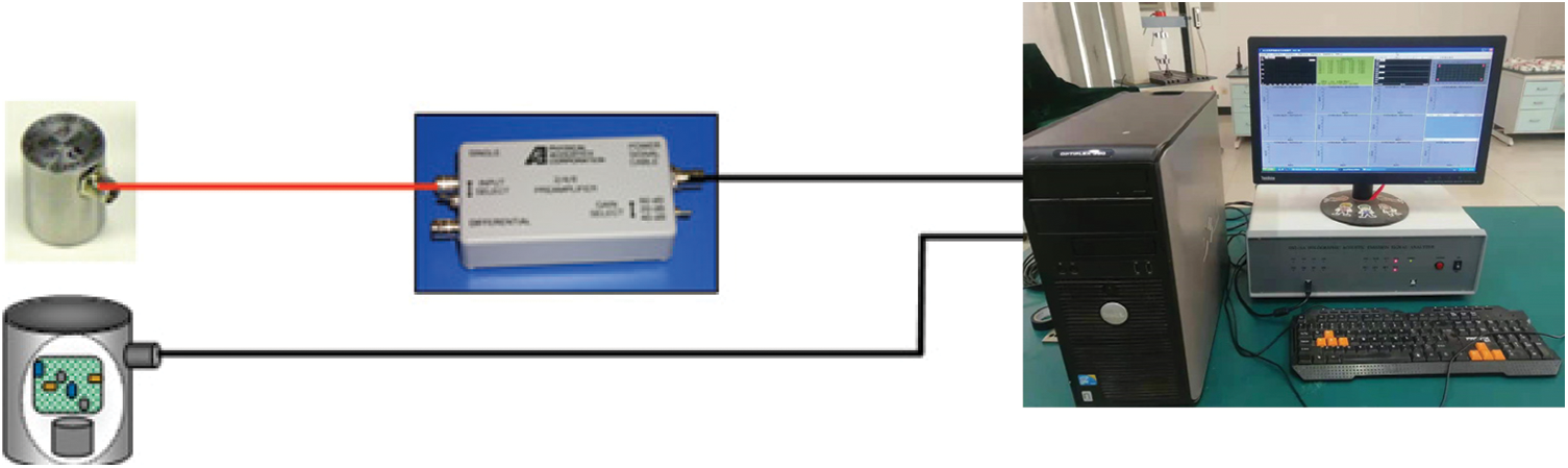
Figure 2: Acoustic emission detection instrument diagram
By examining the simplified diagram depicted in Fig. 3, one can observe that the acoustic emission signal becomes detectable by the sensor only when it surpasses the signal detection threshold. Subsequently, it is displayed on the analysis host. Consequently, the intensity of the acoustic emission signal waveform exhibits a pattern of initially increasing, reaching a peak, and then gradually diminishing until it ceases completely. This shape reflects the process of releasing internal deformation energy in the rock. Through the examination of the acoustic emission signal waveform, additional insights into the process of rock failure can be acquired.
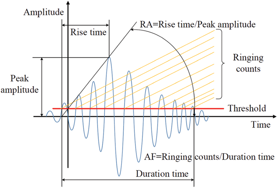
Figure 3: Simplified schematic diagram of acoustic emission signal
In the initial processing of acoustic emission signals, a frequently employed approach is the parameter analysis method [26]. This method transforms the acoustic emission signal into various signal parameters, allowing for further examination and processing of the acoustic emission source’s characteristics. The parameter analysis method encompasses the calculation of several signal parameters, including event count, ring count, energy, amplitude, duration, rise time, among others. Through the analysis of these parameters, a more comprehensive comprehension of the characteristics and fluctuations of the acoustic emission signal can be attained. The analysis outcomes of these parameters play a vital role in evaluating the extent of rock failure and assessing engineering safety. Hence, within the domain of acoustic emission detection, the parameter analysis method serves as a valuable approach for extracting and examining crucial information derived from the acoustic emission signal.
2.2 Experimental Equipment and Setup
The raw coal was transported to the laboratory under sealed conditions after collection. In the laboratory, the raw coal was processed by drilling, cutting, polishing, and cleaving using equipment. It is worth noting that the selected coal samples all came from the same block of raw coal, with the purpose of reducing the impact of coal heterogeneity on the experimental results. A set of circular coal rock specimens with a thickness of 30 mm and a diameter of 76 mm were prepared in this experiment. Artificially induced fractures were made on the specimens, with a length of 14 mm and perpendicular to the bottom diameter, forming a semi-circular specimen as shown in Fig. 4. To conduct tests under different conditions, we divided each type of coal specimen into two groups: the temperature group and the cyclic group.
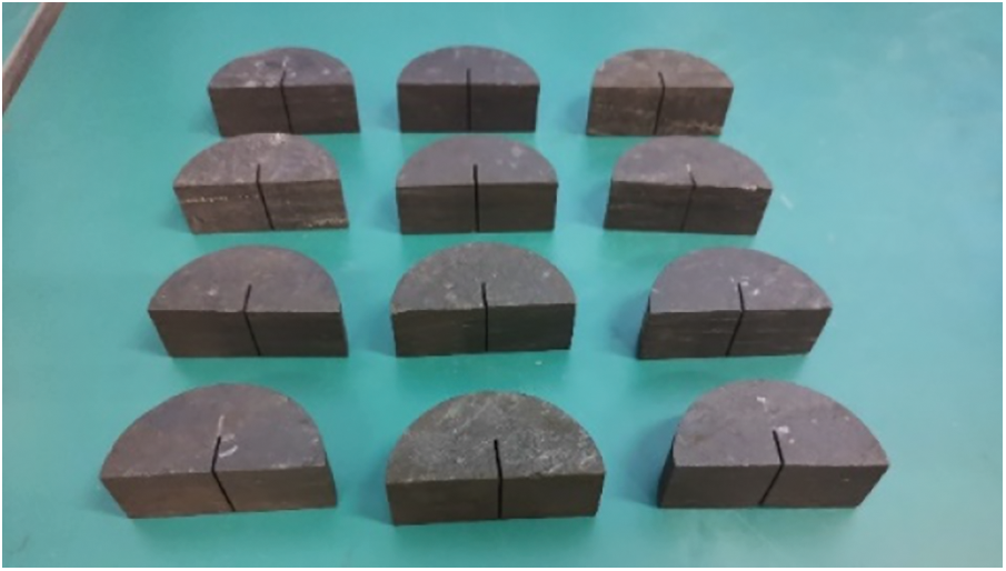
Figure 4: Image of coal rock specimen
The temperature group underwent various temperature treatments, which encompassed the following scenarios: untreated at ambient temperature (20°C), cooling at ambient temperature using liquid nitrogen, heating to 40°C and subsequent cooling with liquid nitrogen, heating to 60°C and subsequent cooling with liquid nitrogen, heating to 80°C and subsequent cooling with liquid nitrogen, and heating to 100°C and subsequent cooling with liquid nitrogen. The cyclic group underwent multiple cycles of treatment, with cycle numbers including 3 cycles, 5 cycles, 7 cycles, and so on. Each cycle involved heating the specimen to 80°C and then liquid nitrogen cooling. Two specimens were tested under each condition. Fig. 5 shows the equipment used in the preparation and liquid nitrogen treatment processes.

Figure 5: Auxiliary equipment
Prior to conducting the three-point bending test on the rock specimen, necessary data collection and processing tasks were performed to ensure the precision and dependability of the experimental outcomes. Subsequently, the processed rock samples were subjected to the three-point bending test. The experimental setup employed in the test is illustrated in Fig. 6. The fundamental principle involves applying force to the press and monitoring the numerical variations on the indicator to quantify the deformation of the rock sample. The specific experimental procedure adheres to the guidelines set by the International Society for Rock Mechanics [27]. The rock specimen is placed between the upper and lower pressure plates of the electronic universal testing machine, with careful alignment of the centerline of the rock sample to coincide with the centerline of the machine. Next, start the electronic universal testing machine and release the clamping screws on both sides of the splitting fixture. Apply pressure at the center of the sample to induce bending deformation. The test is conducted with displacement control at a speed of 0.05 mm/min until completion. After all experiments are finished, seal the crushed coal samples in sealed bags and label them for subsequent analysis. During the experiment, the computer will synchronously display the magnitude of the output force and the deformation of the sample. The schematic diagram of the sample loading is shown in Fig. 7.

Figure 6: Image of three-point bending test equipment

Figure 7: Schematic diagram of sample loading
Opting for a specific set of outcomes to monitor the alterations in the fracture state of the coal rock sample. As presented in Fig. 8, this represents the rock specimen post its exposure to five rounds of liquid nitrogen circulation before undergoing the three-point bending test. The fracture failure boundary line is distinguishable and evident, signifying the modifications endured by the specimen throughout the experiment.
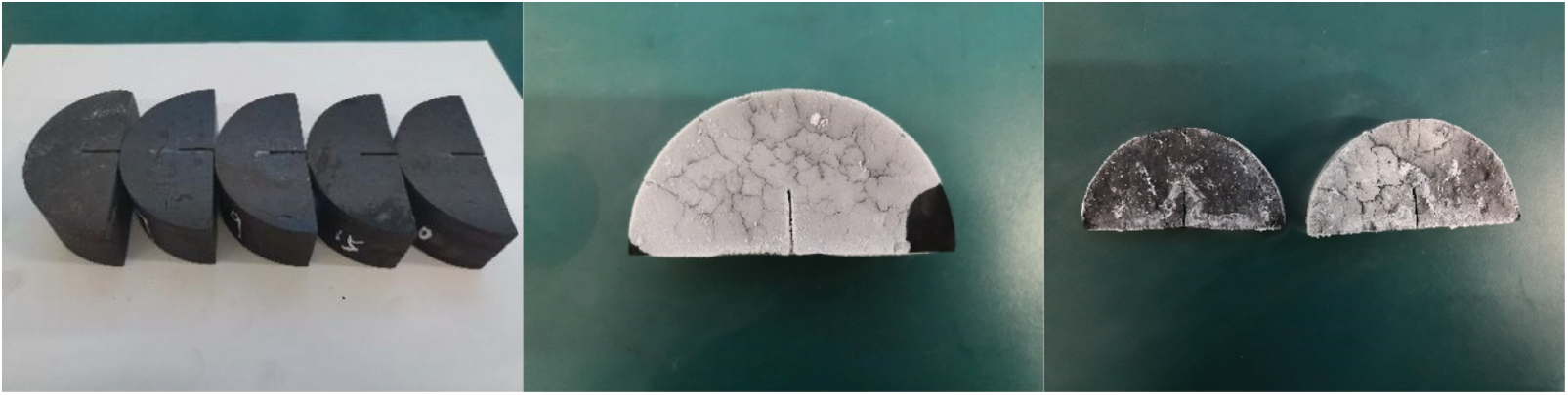
Figure 8: Image of rock sample failure
3 Experimental Results and Analysis
3.1 Mechanical Behavior Analysis
From the experimental results, the fracture pattern of the coal rock can be observed, which shows the complete process from initial loading to final fracture. By graphing the load-displacement curve, it is possible to examine the mechanical impacts and fluctuations experienced by the coal rock specimen during the freezing and thawing cycles with liquid nitrogen. Considering a specific dataset from Fig. 9, it can be observed that, overall, the load-displacement curve of the coal rock exhibits four distinct phases, including the initiation of cracks, elastic deformation, expansion of cracks, and ultimate rock failure stage. These stages represent the mechanical behavior of the coal rock specimen under three-point bending conditions, as well as the influence of liquid nitrogen cycle freezing and thawing treatment.

Figure 9: Load-displacement curves under different treatment methods
Based on the aforementioned diagram, it becomes apparent that the peak load experiences a gradual decline as the initial temperature rises subsequent to the treatment of the sample with liquid nitrogen. Moreover, an escalation in the number of cycles also results in a reduction in the maximum load. Particularly in the case of the 20°C sample, the peak load significantly decreases after liquid nitrogen treatment. This suggests that following the application of liquid nitrogen treatment, the level of damage to the sample intensifies as the temperatures rise and the number of treatment cycles increases. This is attributed to the phenomenon wherein high-temperature rock experiences a sudden drop in external temperature, while the internal temperature decreases at a comparatively slower pace, consequently leading to a substantial temperature gradient. Such a temperature gradient can generate thermal shock loads, causing severe damage to the rock. Rocks are comprised of several diverse materials with varying coefficients of thermal expansion and shrinkage. Therefore, after liquid nitrogen treatment, a significant thermal stress is formed within the rock, further damaging its structure. Furthermore, from the graph, it can also be observed that the number of cycles has a more significant impact on the peak load than temperature. This suggests that as the number of treatment cycles increases, the long-term behavior of the sample after liquid nitrogen treatment may gradually degrade.
In order to conduct an in-depth analysis of the mechanical properties of rocks, the fracture toughness was calculated and the following method [28] was adopted to calculate the fracture toughness under different processing methods based on the load-displacement curve. After calculations, the fracture toughness data shown in Tables 1 and 2 were obtained for result analysis.
where, “
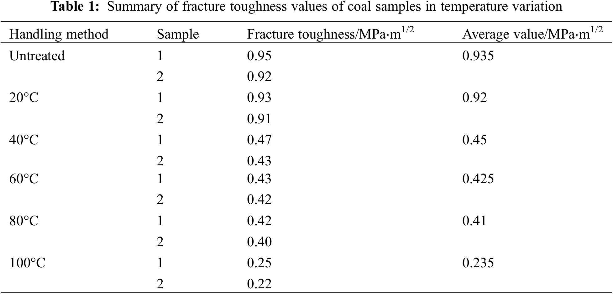
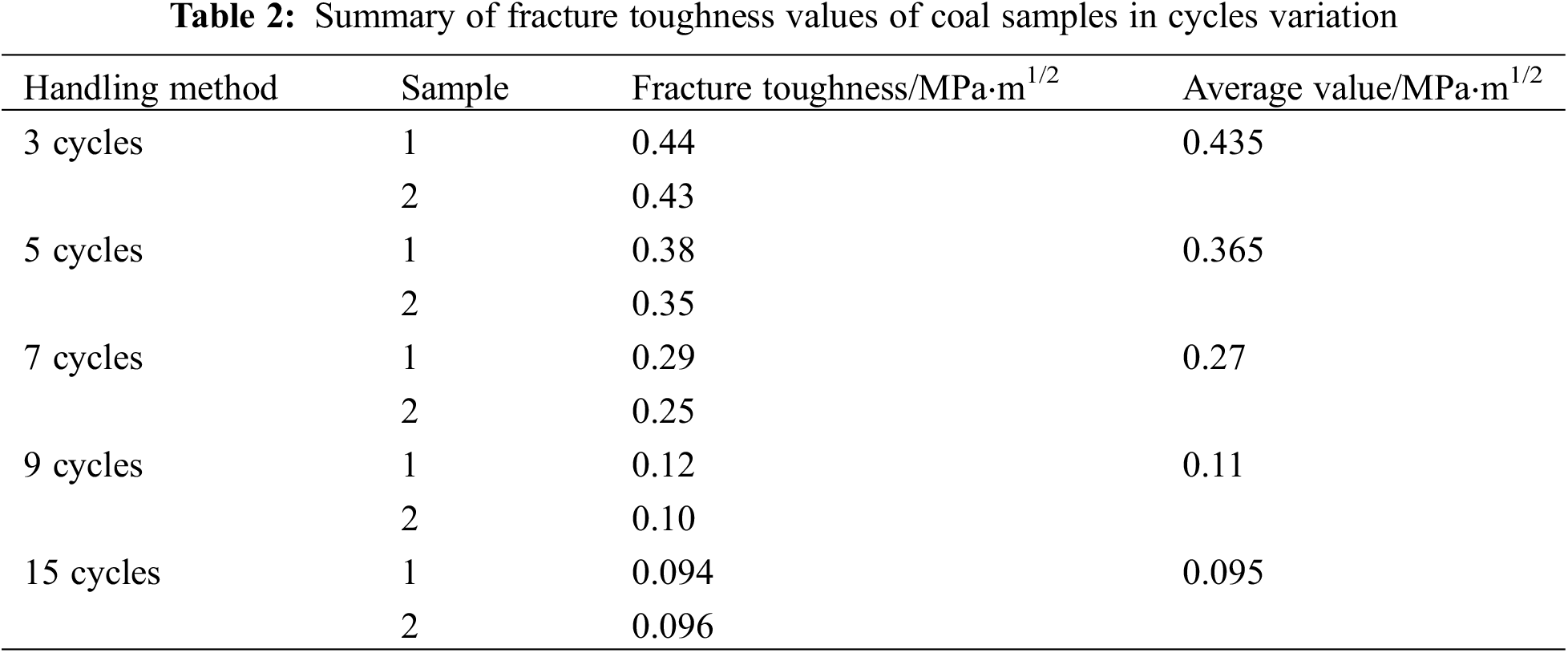

Figure 10: Evolutionary characteristics of
In order to compare the effects of the two processing methods more intuitively, a histogram depicting the average fracture toughness shown in Fig. 11 was plotted. By observing the results, it is evident that regardless of which processing method is used, the fracture toughness of the coal samples gradually decreases. This finding reveals an important phenomenon in the liquid nitrogen fracturing engineering: after a prolonged period of liquid nitrogen treatment, a frozen zone forms around the coal seam, further significantly enhancing the crack resistance of the coal material and effectively suppressing the initiation of coal fractures near the wellbore. Therefore, in conducting fracturing engineering, selecting liquid nitrogen treatment for the wellbore can effectively weaken the crack resistance of the coal material, making it easier for cracks to initiate and propagate near the wellbore, thus greatly improving the transformation effect of the target reservoir. This result provides substantial guidance and basis for the process optimization in liquid nitrogen fracturing engineering.

Figure 11: Fracture toughness under different treatment methods
Based on the data analysis above, the following conclusions can be drawn: as the temperature and the number of liquid nitrogen cooling cycles vary, the fracture toughness of the coal-rock generally shows a decreasing trend. Additionally, under different temperature and cycle conditions, the mechanical properties of the coal-rock exhibit different trends. Under lower temperatures and fewer cycles, the deformation and damage of the coal-rock are relatively small, resulting in a limited decrease in fracture toughness. This suggests that when cooling cycles are performed at relatively low temperatures with a small number of cycles, the physical properties of the coal-rock can still maintain good stability. However, under higher temperatures and increased cycle numbers, the deformation and damage of the coal-rock become more significant, leading to a larger decrease in fracture toughness. In other words, frequent cyclic treatments under high-temperature conditions will have a more pronounced impact on the mechanical performance of the coal-rock.
In summary, these results indicate that liquid nitrogen fracturing treatment has a significant effect on the mechanical properties of coal rock, and this effect is closely related to the treatment temperature and number of cycles. It can be seen that the liquid nitrogen fracturing treatment technology has potential application prospects in the fields of coal mining, mining engineering, and geological disaster control. However, in the actual application process, the development of liquid nitrogen fracturing treatment plans needs to consider many factors, including processing conditions, treatment parameters, and treatment time. Specifically, when developing a liquid nitrogen fracturing treatment plan, it is necessary to comprehensively consider specific geological conditions, engineering requirements, and technical limitations to ensure the physical performance and stability of coal rock.
3.2 Examination of AE Features of Coal Rock
3.2.1 Experimental Findings on the AE Traits
In this research, a quantitative analysis and assessment of various acoustic emission (AE) parameters were carried out to comprehend the AE activity. These parameters include cumulative AE count, cumulative AE energy, AF value, RA value, and more. The cumulative AE count signifies the total number of oscillations surpassing a predefined threshold and serves as an indicator of the intensity of AE activity. Cumulative AE count and cumulative AE energy represent the accumulated sum of AE counts and energies until a specific moment, respectively. Any signal surpassing the threshold is considered an impact event, reflecting the overall quantity and frequency of AE activity. The AF value calculates the average frequency by dividing the AE count exceeding the threshold by the duration of AE impacts, measured in kilohertz (KHz). On the other hand, the RA value is obtained by dividing the time taken for a signal to cross the threshold and reach maximum amplitude by the amplitude of the AE signal, measured in milliseconds per volt (ms/V). Employing these parameters aids in evaluating the structural health and predicting potential failure scenarios.
Based on the outcomes of the acoustic emission (AE) testing, this investigation has produced multiple diagrams that depict the correlations among load-time, AE ring count-cumulative ring count, and energy-cumulative energy. Within these diagrams, Figs. 12 and 13 represent the charts with cycle number as a variable, while Figs. 14 and 15 represent the charts with temperature as a variable. These charts provide a more intuitive way of presenting the data, helping us to better understand the characteristics and trends of AE activity.

Figure 12: Change of AE hits with the change of cycle times
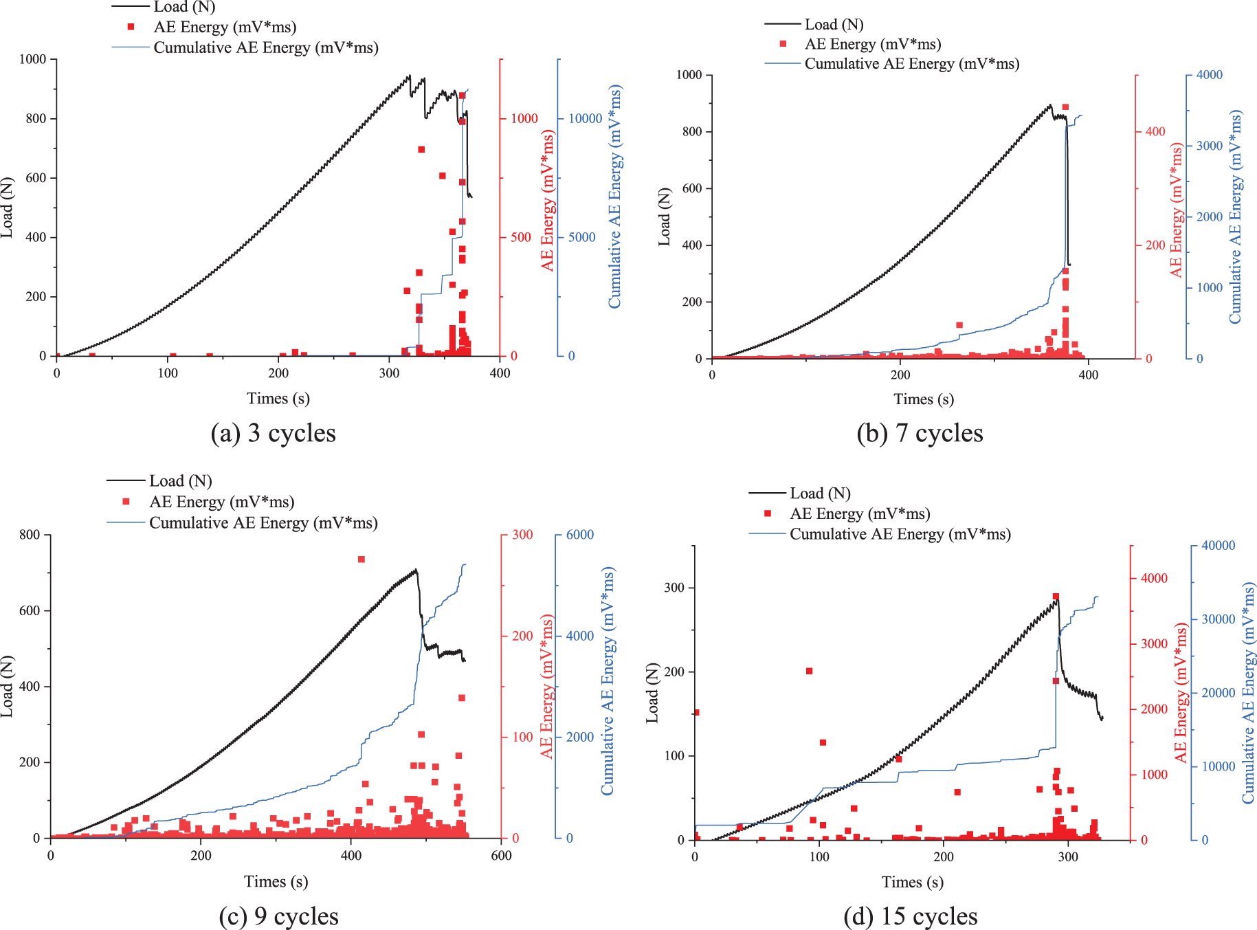
Figure 13: Change of AE energy with the change of cycle times
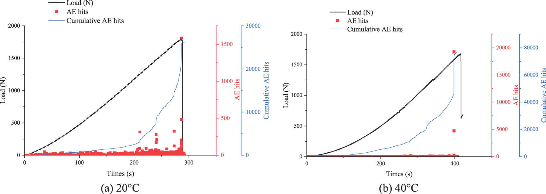
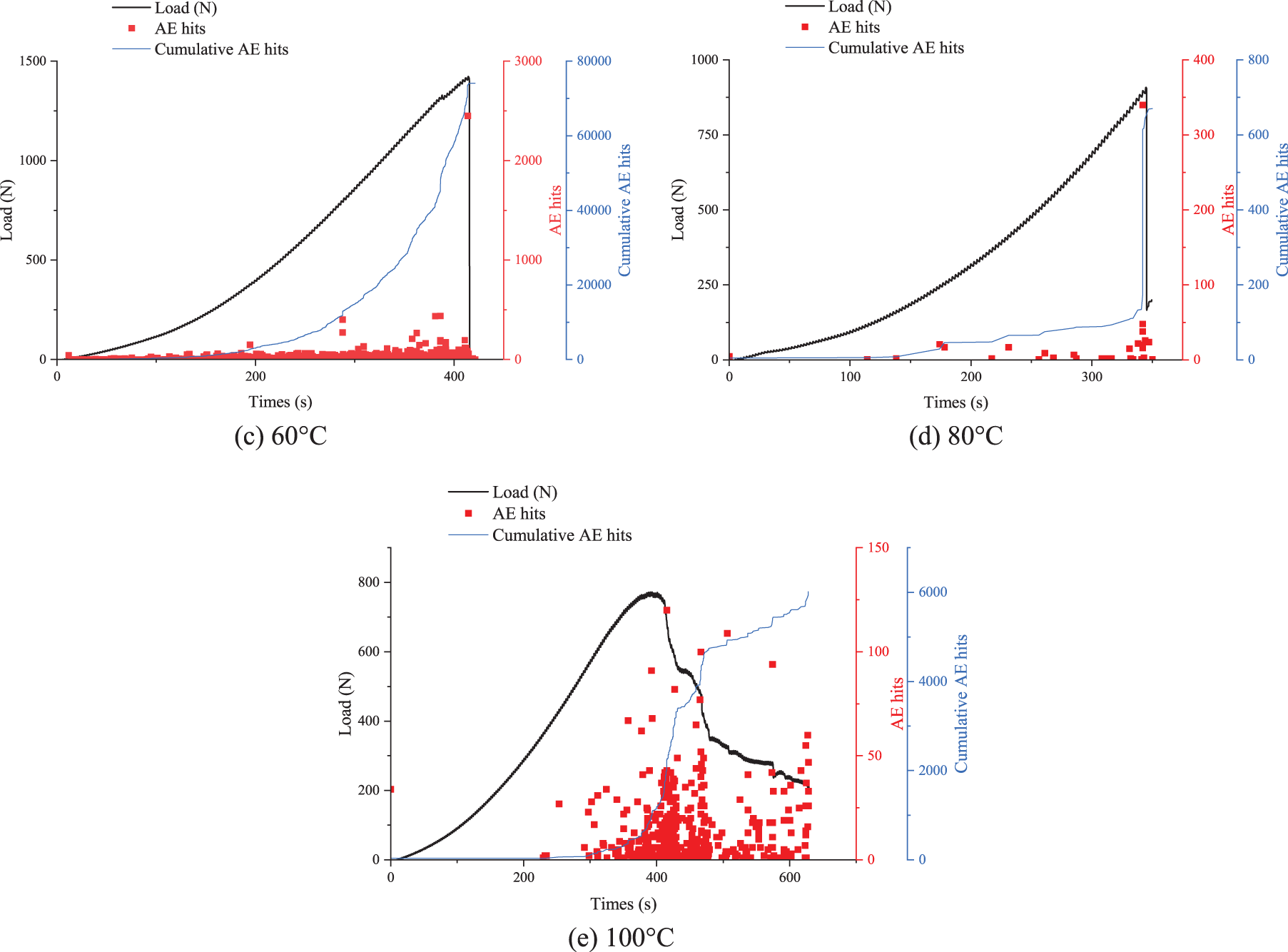
Figure 14: Change of AE hits with the change of temperature


Figure 15: Change of AE energy with the change of temperature
Based on the findings derived from the load-time graph, it is possible to examine the fluctuations in acoustic emission activity across various time and load scenarios. The results indicate that, during loading, both ring count and energy count exhibit an overall decreasing trend. Under conditions of lower loads, there is a slower rate of increase in ring count and energy count. The cumulative ring count and cumulative energy charts illustrate the accumulation of ring count over time. Typically, the ring count and energy count also reach their peak values when the load reaches its peak. This suggests that as the cycle numbers increase and the load value grows, the damage to the coal body becomes more severe.
According to the aforementioned graph, as the initial temperature of the sample rises, there is a decrease in both the ring count and energy count associated with the acoustic emission activity. Additionally, under conditions of lower loads, there is a slower increase in ring count and energy count. However, in general, the highest values for ring count and energy count are observed when the load reaches its peak. This observation suggests that as the initial temperature increases and the applied force intensifies, the damage to the coal body becomes more severe, resulting in a decrease in the number of generated acoustic emission signals and a reduction in the energy produced. Ultimately, the acoustic emission activity can be categorized into four distinct stages. The first stage is the initial formation of cracks, during which there is minimal acoustic emission activity. In the second phase, the coal-rock mass undergoes elastic deformation, resulting in the generation of low-energy and prolonged acoustic emission signals. Moving on to the third stage, the coal-rock mass experiences non-elastic deformation, leading to a substantial increase in the number of high-density acoustic emission signals with escalating energy levels. At the point of maximum load, the energy of the acoustic emission signals also attains its peak value. During the fourth stage, known as the post-peak failure phase, the acoustic emission activity continues, albeit with a declining energy level. Upon analyzing the ring count graph, it becomes apparent that the cyclic coal-rock specimen’s ring count demonstrates a significant increase with the growth in both the number of freeze-thaw cycles using liquid nitrogen and the initial temperature. As the number of freeze-thaw cycles using liquid nitrogen increases, there is a tendency for enhanced acoustic emission activity during the fracture, plastic deformation, compaction, and elasticity stages as the load progressively augments. These acoustic emission signals during the process of coal-rock fracture serve as indicators of the fluctuating level of activity within the coal-rock. It is crucial to highlight that an escalation in the number of cycles has the potential to result in damage occurring in particular areas. After applying the load, the acoustic emission ring count suddenly increases, leading to a sharp rise in the cumulative ring count curve. To summarize, the implementation of liquid nitrogen freeze-thaw treatment utilizes the crack-generating attributes of liquid nitrogen, triggers the inherent damage potential of coal-rock, impacts the distribution of damage, and brings about modifications to the properties of coal-rock.
Based on the analysis of energy count, it can be inferred that the acoustic emission energy of the coal-rock sample amplifies as the load increases, with four prominent spikes corresponding to 20%, 50%, 60%, and 80% of the load peak. When comparing the acoustic emission ring count and energy data of coal-rock samples before and after undergoing liquid nitrogen treatment, it becomes evident that both metrics demonstrate a significant rise following the freeze-thaw treatment with liquid nitrogen. However, this phenomenon’s likelihood gradually dwindles. Specifically, after exerting pressure, acoustic emission events take place between the coal-rock mass and the loading plate. Subsequently, internal cracks in the coal-rock sample close under the action of the load, inducing acoustic emission activity. As the applied force persists, the acoustic emission energy undergoes minor fluctuations until reaching the fracture stage. With an escalating applied pressure, the acoustic emission activity becomes more intense, eventually culminating in the failure of the coal-rock sample. During all stages of the peak load and beyond, the cumulative energy curve of acoustic emission displays a synchronized upward trend with the load curve, marked by significant spikes.
In previous studies, some researchers used the JCMS-IIIB5706 device to classify rock fractures [31]. The distribution map is shown in Fig. 16. According to the research results, RA and AF are two important parameters of acoustic emission (AE). When dealing with AE parameters, it is necessary to ensure that the obtained parameters have consistent units. If there are inconsistencies in the units, appropriate numerical conversion should be applied. Otherwise, using unconverted data directly may result in inconsistent units in the final results.

Figure 16: Distribution diagram of tensile-shear
Furthermore, it was found in the study that the unified treatment of AE parameters is of great significance for effective analysis and interpretation of data. By correctly handling parameter units and adopting consistent quantification methods, the characteristics and properties of rock fractures can be better evaluated. Therefore, ensuring the consistency of data units is crucial when using AE data for analysis.
The acoustic emission parameter RA (as defined in Eq. (2)) refers to the ratio of rise time to amplitude, with units of ms/V.
The acoustic emission parameter AF (as defined in Eq. (3)) represents the ratio of ring count to duration, with units of KHz.
The analysis results of Fig. 17 show that most of the data points are mainly distributed above the diagonal line and near the AF axis. This suggests that there is a substantial rise in the fraction of tension fracture points in the RA-AF distribution diagram with the increase in temperature, following the treatment of the sample with liquid nitrogen. This suggests a trend of gradually increasing tensile failure proportion of the coal specimen with the initial temperature increase. Therefore, in the process of liquid nitrogen fracturing of coal specimens, we should try to increase the temperature of the coal specimen to improve the fracturing effect and reduce work risk as much as possible. Further analysis results also show that the effect of liquid nitrogen fracturing varies at different temperatures. Under low temperature conditions, the number of cracks generated within coal is relatively small. However, as the temperature increases, the number of cracks generated within coal also increases, making it challenging to ensure a reliable fracturing effect. Therefore, when conducting liquid nitrogen fracturing experiments, it should be conducted within an appropriate temperature range.
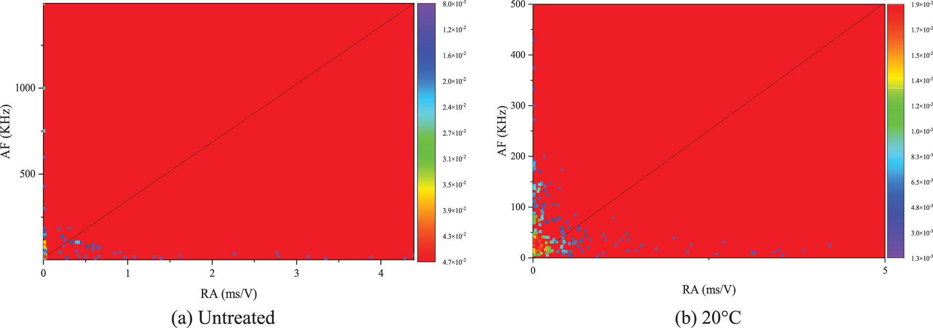

Figure 17: Schematic diagram of RA-AF distribution under temperature changes
Through the analysis of Fig. 18, it can be observed that with an increase in the number of heating and liquid nitrogen cooling cycles, the proportion of tension fracture points in the RA-AF distribution diagram significantly increases. This suggests that with an increase in the number of cycles of liquid nitrogen treatment, there is a corresponding rise in the proportion of tension failure observed in the coal specimen. Therefore, when conducting liquid nitrogen fracturing experiments, it is advisable to subject the coal specimen to multiple cycles of treatment to achieve better fracturing effects. In addition, before conducting liquid nitrogen fracturing experiments, it is necessary to adequately prepare the samples to ensure better results. For example, impurities in the samples should be removed as much as possible, and the uniformity and integrity of the samples should be ensured.

Figure 18: Schematic diagram of RA-AF distribution under changes in cycle count
The utilization of the liquid nitrogen fracturing method presents a viable and promising approach for extracting coalbed methane. Nonetheless, in real-world scenarios, it is imperative to take into account variables such as temperature and treatment cycles. It is essential to scientifically and judiciously regulate and enhance the liquid nitrogen fracturing process to attain superior outcomes and maximize economic advantages.
(1) The liquid nitrogen fracturing technique can be effectively applied in the extraction of coalbed methane. It can avoid water resource waste and environmental pollution that may occur during hydraulic fracturing processes, and it can extract coalbed methane more efficiently. The effectiveness of liquid nitrogen fracturing is heavily influenced by temperature and the frequency of treatment cycles. As the temperature rises, the peak load-bearing capacity of coal rock steadily declines. Similarly, when the number of treatment cycles is increased at a constant temperature, the peak load-bearing capacity of coal rock experiences a corresponding decrease.
(2) With an increase in the number of freeze-thaw cycles of low-temperature nitrogen treatment, coupled with a corresponding rise in treatment temperature, there is a noticeable boost in the magnitude of acoustic emission activity observed during load-bearing stages such as elasticity, plasticity, compaction, and fracture of coal rock. When a significant load is applied, the number of acoustic emission events undergoes a rapid surge, which results in a sharp increase in the cumulative ringing count curve. This suggests that the use of low-temperature nitrogen freeze-thaw cycles and high-temperature treatments can make complete use of the decomposition effect of low-temperature nitrogen, leading to the activation of the damage potential present in coal rock itself, which in turn impacts its mechanical properties.
(3) During the liquid nitrogen fracturing procedure, coal rock samples predominantly undergo the development, spread, and rupture of tensile cracks, succeeded by the occurrence and enlargement of shear fractures. Compared with the increase of initial temperature, the increase of cycling times can induce more micro-cracks in coal.
(4) To ensure the accuracy and stability of the treatment effect, the formulation of a liquid nitrogen fracturing treatment plan needs to take into account various factors such as geological conditions, engineering requirements, and technical limitations. Furthermore, in order to enhance the effectiveness of the application of liquid nitrogen fracturing treatment technology, more research should be conducted to investigate the impact mechanism of this technology on the mechanical properties of coal rock, optimize treatment parameters, and improve treatment efficiency and accuracy.
Acknowledgement: None.
Funding Statement: The authors gratefully acknowledge the National Natural Science Foundation (52004285), Fundamental Research Funds for the Central Universities from China University of Mining and Technology-Beijing (JCCXXNY06), the Open Fund of State Key Laboratory Cultivation Base for Gas Geology and Gas Control (Henan Polytechnic University) (WS2021A03).
Author Contributions: The authors confirm contribution to the paper as follows: study conception and design: Teng Teng, Linchao Wang; data collection: Yuhe Cai; analysis and interpretation of results: Yanzhao Zhu, Teng Teng; draft manuscript preparation: Teng Teng, Yuhe Cai. All authors reviewed the results and approved the final version of the manuscript.
Availability of Data and Materials: The data and materials used in this study are available upon request from the corresponding author.
Conflicts of Interest: The authors declare that they have no conflicts of interest to report regarding the present study.
References
1. Kumari, W. G. P., Ranjith, P. G. (2019). Sustainable development of enhanced geothermal systems based on geotechnical research–A review. Earth-Science Reviews, 199, 102955. https://doi.org/10.1016/j.earscirev.2019.102955 [Google Scholar] [CrossRef]
2. Chakhmakhchev, A., Fryklund, B. (2008). Critical success factors of CBM development-implications of two strategies to global development. World Petroleum Congress, Madrid, Spain. Portland Press. [Google Scholar]
3. Xiao, S., Ren, Q., Cheng, Y., Wang, H., Zhang, L. et al. (2022). Research and application of high-pressure water jets drilling and repairing failure drainage borehole for enhancing coalbed methane recovery in underground coal mines. Geomechanics and Geophysics for Geo-Energy and Geo-Resources, 8(6), 191. [Google Scholar]
4. Jha, P., Ghosh, S., Vidyarthi, A. S., Singh, J., Mukhopadhyay, K. et al. (2022). Unravelling the microbial community structure and function of coal-bed methane producing formation water of Jharia coal mines using metagenomics approach. Fuel, 317, 123459. https://doi.org/10.1016/j.fuel.2022.123459 [Google Scholar] [CrossRef]
5. Wrobel, M., Mishuris, G., Papanastasiou, P. (2021). On the influence of fluid rheology on hydraulic fracture. International Journal of Engineering Science, 158, 103426. https://doi.org/10.1016/j.ijengsci.2020.103426 [Google Scholar] [CrossRef]
6. Mahesar, A. A., Shar, A. M., Ali, M., Tunio, A. H., Uqailli, M. A. et al. (2020). Morphological and petro physical estimation of eocene tight carbonate formation cracking by cryogenic liquid nitrogen; a case study of Lower Indus basin, Pakistan. Journal of Petroleum Science and Engineering, 192, 107318. https://doi.org/10.1016/j.petrol.2020.107318 [Google Scholar] [CrossRef]
7. Shouldice, S. P. (1964). Liquid nitrogen developments and applications in drilling and completion operations. Journal of Canadian Petroleum Technology, 3(4), 158–164. [Google Scholar]
8. Kalam, S., Afagwu, C., Al Jaberi, J., Siddig, O. M., Tariq, Z. et al. (2021). A review on non-aqueous fracturing techniques in unconventional reservoirs. Journal of Natural Gas Science and Engineering, 95, 104223. https://doi.org/10.1016/j.jngse.2021.104223 [Google Scholar] [CrossRef]
9. Halbert, W. G. (1971). Method of increasing the permeability of a subterranean hydrocarbon bearing formation: US 3602310. [Google Scholar]
10. Sun, Y., Zhai, C., Xu, J., Cong, Y., Zheng, Y. (2021). Experimental study on pore structure evolution of coal in macroscopic, mesoscopic, and microscopic scales during liquid nitrogen cyclic cold-shock fracturing. Fuel, 291, 120150. https://doi.org/10.1016/j.fuel.2021.120150 [Google Scholar] [CrossRef]
11. Cha, M., Yin, X., Kneafsey, T., Johanson, B., Alqahtani, N. et al. (2014). Cryogenic fracturing for reservoir stimulation–Laboratory studies. Journal of Petroleum Science and Engineering, 124, 436–450. https://doi.org/10.1016/j.petrol.2014.09.003 [Google Scholar] [CrossRef]
12. Grundmann, S. R., Rodvelt, G. D., Dials, G. A., Allen, R. E. (1998). Cryogenic nitrogen as a hydraulic fracturing fluid in the devonian shale. SPE Eastern Regional Meeting, Pittsburgh, Pennsylvania. [Google Scholar]
13. Mc Daniel, B. W., Grundmann, S. R., Kendrick, W. D., Wilson, D. R., Jordan, S. W. (1997). Field applications of cryogenic nitrogen as a hydraulic fracturing fluid. Journal of Petroleum Technology, 50(3), 561–572. [Google Scholar]
14. Cai, C., Ren, K., Tao, Z., Xing, Y., Gao, F. et al. (2022). Experimental investigation of the damage characteristics of high-temperature granite subjected to liquid nitrogen treatment. Natural Resources Research, 31(5), 2603–2627. [Google Scholar]
15. Li, H., Zuo, J., Wang, L., Li, P., Xu, X. (2020). Mechanism of structural damage in low permeability coal material of coalbed methane reservoir under cyclic cold loading. Energies, 13(3), 519. [Google Scholar]
16. Kaiser, E. J. (1950). A study of acoustic phenomena in tensile test (Doctoral Dissertation). Technical University of Munich, Germany. [Google Scholar]
17. Munoz-Ibanez, A., Delgado-Martín, J., Herbón-Penabad, M., Alvarellos-Iglesias, J. (2021). Acoustic emission monitoring of mode I fracture toughness tests on sandstone rocks. Journal of Petroleum Science and Engineering, 205, 108906. https://doi.org/10.1016/j.petrol.2021.108906 [Google Scholar] [CrossRef]
18. Lockner, D. (1993). The role of acoustic emission in the study of rock fracture. International Journal of Rock Mechanics and Mining Sciences & Geomechanics Abstracts, 30(7), 883–899. [Google Scholar]
19. Shah, K. R., Labuz, J. F. (1995). Damage mechanisms in stressed rock from acoustic emission. Journal of Geophysical Research: Solid Earth, 100(B8), 15527–15539. [Google Scholar]
20. Akdag, S., Karakus, M., Nguyen, G. D., Taheri, A., Bruning, T. (2021). Evaluation of the propensity of strain burst in brittle granite based on post-peak energy analysis. Underground Space, 6(1), 1–11. [Google Scholar]
21. Wu, X., Huang, Z., Zhang, S., Cheng, Z., Li, R. et al. (2019). Damage analysis of high-temperature rocks subjected to LN2 thermal shock. Rock Mechanics and Rock Engineering, 52(8), 2585–2603. [Google Scholar]
22. Kanagawa, T., Hayashi, M., Nakasa, H. (1977). Estimation of spatial geo-stress components in rock samples using the kaiser effect of acoustic emission. Proceedings of the Japan Society of Civil Engineers, vol. 258, pp. 63–75. Japan Society of Civil Engineers. [Google Scholar]
23. Mao, X., Zhang, L., Li, T., Liu, H. (2009). Properties of failure mode and thermal damage for limestone at high temperature. Mining Science and Technology (China), 19(3), 290–294. [Google Scholar]
24. Dwivedi, R. D., Goel, R. K., Prasad, V. V. R., Sinha, A. (2008). Thermo-mechanical properties of Indian and other granites. International Journal of Rock Mechanics and Mining Sciences, 45(3), 303–315. [Google Scholar]
25. Yang, S., Tian, W., Elsworth, D., Wang, J., Fan, L. (2020). An experimental study of effect of high temperature on the permeability evolution and failure response of granite under triaxial compression. Rock Mechanics and Rock Engineering, 53, 4403–4427. https://doi.org/10.1007/s00603-019-01982-7 [Google Scholar] [CrossRef]
26. Rodríguez, P., Celestino, T. B. (2019). Application of acoustic emission monitoring and signal analysis to the qualitative and quantitative characterization of the fracturing process in rocks. Engineering Fracture Mechanics, 210, 54–69. https://doi.org/10.1016/j.engfracmech.2018.06.027 [Google Scholar] [CrossRef]
27. Ulusay, R. (2022). Rock characterization and testing and future trends: Highlighting the ISRM suggested methods. ISRM International Conference on Advances in Rock Mechanics-TuniRock, Hamammet, Tunisia. [Google Scholar]
28. Lim, I. L., Johnston, I. W., Choi, S. K. (1993). Stress intensity factors for semi-circular specimens under three-point bending. Engineering Fracture Mechanics, 44(3), 363–382. [Google Scholar]
29. Ayatollahi, M. R., Aliha, M. R. M. (2007). Wide range data for crack tip parameters in two disc-type specimens under mixed mode loading. Computational Materials Science, 38(4), 660–670. [Google Scholar]
30. Qin, L., Ma, C., Li, S., Lin, H., Wang, P. et al. (2022). Mechanical damage mechanism of frozen coal subjected to liquid nitrogen freezing. Fuel, 309, 122124. https://doi.org/10.1016/j.fuel.2021.122124 [Google Scholar] [CrossRef]
31. Wang, L., Zhang, B., Qian, Z., Le, L., Hong, J. (2019). Experimental investigation of the acoustics emission characteristics of two types of brittle rocks under uniaxial compression. Journal of Engineering Geology, 27(4), 699–705. [Google Scholar]
Cite This Article
 Copyright © 2024 The Author(s). Published by Tech Science Press.
This work is licensed under a Creative Commons Attribution 4.0 International License , which permits unrestricted use, distribution, and reproduction in any medium, provided the original work is properly cited.
 Downloads
 Citation Tools