
 Submit a Paper
 Propose a Special lssue
 Open Access
ARTICLE
Influence of Methane-Hydrogen Mixture Characteristics on Compressor Vibrations
High Performance Computing Center, Perm National Research Polytechnic University, Perm, 614990, Russia
* Corresponding Author: Ivan E. Cherepanov. Email:
(This article belongs to the Special Issue: Advanced Problems in Fluid Mechanics)
Fluid Dynamics & Materials Processing 2024, 20(5), 1031-1043. https://doi.org/10.32604/fdmp.2024.048494
Received 09 December 2023; Accepted 15 April 2024; Issue published 07 June 2024
 View Full Text
 Download PDF
Abstract
A transition to clean hydrogen energy will not be possible until the issues related to its production, transportation, storage, etc., are adequately resolved. Currently, however, it is possible to use methane-hydrogen mixtures. Natural gas can be transported using a pipeline system with the required pressure being maintained by gas compression stations. This method, however, is affected by some problems too. Compressors emergency stops can be induced by vibrations because in some cases, mechanical methods are not able to reduce the vibration amplitude. As an example, it is known that a gas-dynamic flow effect in labyrinth seals can lead to increased vibrations. This paper presents the numerical simulation of rotor oscillations taking into account a gas-dynamic load. The influence of a transported mixture on the oscillatory process is investigated. Mixtures consisting of methane and hydrogen in various proportions and an air mixture are considered. The results are discussed for various operating pressures and include the rotor motion trajectories and oscillation frequency spectra obtained numerically. It is shown that the gas mixture composition has a significant effect on the oscillations and their occurrence. Hydrogen as a working fluid reduces the vibration amplitude. Operating a compressor with hydrogen leads to a decrease in the resonant frequency, bringing it closer to the operating one. However, the operating pressure at which maximum oscillations are observed depends slightly on the gas mixture composition.Keywords
Nomenclature
| | Fluid density |
| | Velocity vector |
| | Time |
| | Pressure |
| | Dynamic viscosity |
| | Kronecker delta function |
| | Total enthalpy |
| | Fluid temperature |
| | Thermal conductivity |
| | Molar mass |
| | Universal gas constant |
| | Isobaric heat |
| | Vector displacement |
| | Lame parameters |
| | Unit tensor |
| | Young’s modulus |
| | Poisson’s ratio |
| | Material density |
| | Mass force density |
| | External forces density |
Currently, issues related to the possibility of transition from fossil hydrocarbon fuels to hydrogen fuel are being widely studied. An undeniable advantage of hydrogen fuels is their high environmental friendliness, since the combustion product is water vapor. In addition, the combustion temperature and specific heat of combustion of hydrogen fuel exceed those of fossil hydrocarbon fuels [1]. The transition to hydrogen energy is a complex, complex task. It is necessary to resolve issues related to industrial production, storage, transportation, safety, embrittlement of materials in contact with hydrogen, etc.
An economic analysis [2] of various transporting hydrogen fuel methods showed that the use of pipelines has the greatest potential in the long term compared to rail and road transport. The main problems of using the existing gas transportation system are the high ability of hydrogen to penetrate metal barriers [3] and the embrittlement of gas pipeline walls. However, the existing gas transportation system allows for the transportation of natural gas with a hydrogen content of up to 10%, with the prospect of increasing to 20% [4].
A number of works [5–7] are devoted to the transportation of a methane-hydrogen mixture through pipelines. The authors obtained the dependences of the pressure distribution along the length of the pipeline for various hydrogen concentrations in the methane-hydrogen mixture. It is noted that in order to deliver to the consumer the energy equivalent of the currently transported natural gas, it is necessary to increase the pressure at the entrance to the gas pipeline in proportion to the hydrogen concentration.
The gas transmission system consists not only of pipelines and distribution units connecting production sites with consumers but also gas compressor stations that maintain the pressure of the transported gas, which decreases due to friction losses.
An emergency shutdown of a station can lead to losses. One of the reasons for emergency stops is the increased level of vibrations. Compressor rotor vibrations near bearing supports must not exceed up to 40 microns.
Vibration causes may include residual mechanical imbalances due to inaccurate parts manufacturing, asymmetrical elements, non-uniformity of work piece material, and assembly errors. To eliminate mechanical imbalances, balancing is used [8].
To reduce leaks between compressor stages, labyrinth seals are used, which are subject to high requirements for operational reliability [9]. At the same time, the use of non-contact gas-dynamic seals in a compressor design can lead to unstable, self-exciting behavior of a rotor [10]. Work [11] presents a case of increased rotor vibrations due to the occurrence of non-conservative gas-dynamic forces in labyrinth seals. When trying to bring the compressor to its nominal operating mode, low-frequency vibration occurred, which led to an emergency stop.
Thus, in a number of cases, existing mechanical balancing methods fail to reduce the magnitude of vibrations to the required values. It is necessary to clarify existing methods and search for unaccounted factors that lead to a vibration occurrence. Such a factor may be taking into account gas dynamics when modeling rotor dynamics.
There is a linear model of gas-dynamic forces acting on a rotor, which is used in a rotor dynamics analysis [12]. The input parameters of such a model are rotor dynamic coefficients-stiffness and damping coefficients. To determine them, theoretical, experimental and numerical studies are carried out [13–17]. A nonlinear model of gas-dynamic forces is described in [18]. Using this model, the dynamics of a single-mass rotor model wereassessed.
Researchers perform many experiments in an attempt to identify the influence of various geometric factors, but using a linear model does not allow studying a process nature.
The work [19] presents the results of numerical modeling of a compressor rotor taking into account gas in the gaps of labyrinth seals. The study showed that with a certain combination of parameters, an uncontrolled increase in the amplitude of rotor oscillations occurs. In [20], the influence of geometric, kinematic, and gas-dynamic parameters on the occurrence of oscillations is shown. At the same time, the authors did not consider the issue of the influence of the nature of the gas on vibrations. At the same initial pressure and temperature, the gases will have different densities, which affects an oscillation dynamics. The difference in gas viscosity affects vibration damping.
Despite a large number of studies on rotor vibrations caused by unsteady forces in labyrinth seals, there are practically no studies devoted to a compressor operation using hydrogen. Therefore, the work purpose is to assess a rotor vibrations possibility in a hydrogen compressor. To achieve this purpose, it is necessary to solve the following tasks:
1. Assess the influence of a gas mixture composition on a vibrations occurrence in labyrinth seals.
2. Determine the effect of hydrogen concentration in a mixture on vibrations amplitude.
3. Compare vibration frequencies at which a maximum vibration amplitude is observed.
Replacing natural gas with a methane-hydrogen mixture in gas pipelines may lead to a change in the level of vibration of compressor rotors and require additional assessment of the performance of existing compressor stations, so this issue requires research.
The numerical model is presented in Fig. 1. It consists of a rotor 1 with a disk 2 installed in elastic supports 3. On the outer surface of the disk there is a gas-dynamic gap 4, corresponding to a labyrinth seal. From the outside, the gas-dynamic gap is limited by ring 5. At the initial moment of time, the rotor is not deformed, and the rotation speed is ω0. The outer ring is non-deformable. The gap at the initial time moment is filled with gas at given initial values of pressure and temperature. The calculations explicitly took into account a rotation and Earth’s gravity. At one of the ends of the rotor, an axial movements limitation was set to unambiguously define the model in space. A detailed model description is presented in [21].
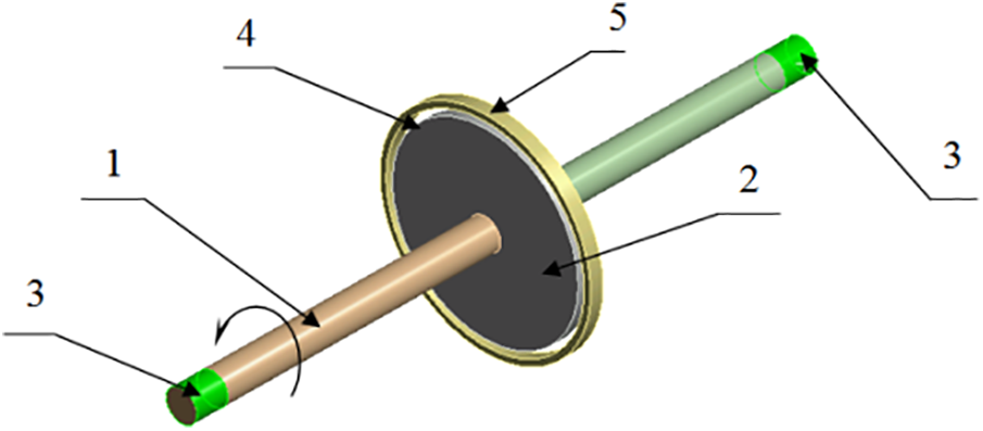
Figure 1: Numerical model: 1–rotor; 2–disk; 3–bearing supports; 4–gas-dynamic gap; 5–ring
The mathematical model is based on non-stationary equations of fluid dynamics and mechanics of deformable solids. Fluid motion equations includingmass, momentum and energy governing laws, are closed by the ideal gas state equation and the turbulence model [22], as well as initial and boundary conditions. The mathematical model of the fluid dynamic problem includes the following equations:
Continuity equation:
Momentum equation:
The relationship for determining viscous stresses has the form:
Energy equation:
The equations described above are supplemented with constitutive relations of state for the density and enthalpy. For an ideal gas the following equations are valid:
The compressor rotor movement is described by differential equations in displacement within the framework of the linear elasticity theory. Limiting ourselves to the linear elasticity theory to describe the rotor movement, the smallness of possible deformations is assumed, which are determined through displacement gradients:
Since the elastic deformation process is associated with inertial forces acting on structural elements at the moment of rotation, and external influences caused by the influence of fluid mass transfer in the gas compressor compressor, forces called stresses arise on the surface of the solid body. The relationship between the resulting stresses and deformations is isotropic Hooke’s law [23]:
The Lamé parameters are determined by the following equations:
The differential motion equations of a continuous medium, which is the compressor rotor, follow from the static equilibrium equations when taking into account volumetric inertia forces:
The equations of static equilibrium when taking into account volumetric inertia forces have the form:
In this case, the material density is a constant value, since the rotor material is assumed to be homogeneous, i.e., its physical and mechanical properties are the same at all points of the body. The mass forces density, in the general case, is a function of spatial coordinates and is formulated from physical considerations about the processes occurring inside the body:
However, this article does not imply the presence of internal mass sources, i.e., external forces are determined from the boundary conditions caused by external interaction.
Using the above relationships, it is possible to obtain differential motion equations of the rotor compressor in displacements:
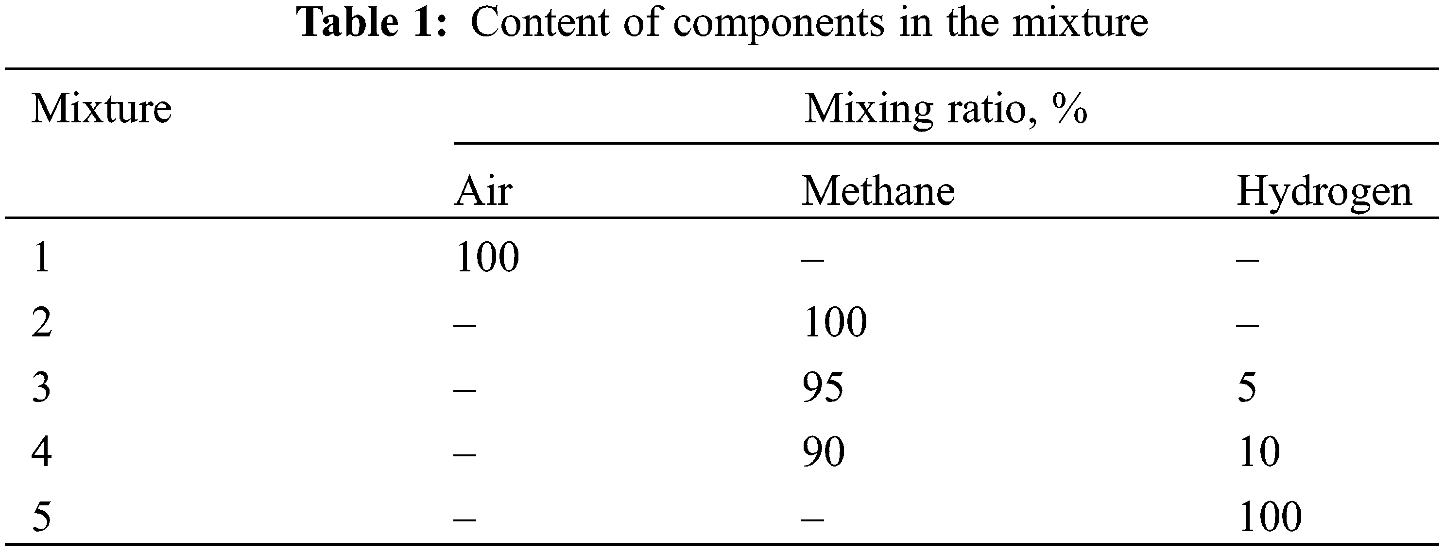
Calculations were carried out for several types of mixtures presented, see Table 1, differing in component composition and concentration. Mixture No. 1 corresponds to the case of acceptance tests at the manufacturer, mixture No. 2-natural gas, which is transported in the existing gas transmission system, mixtures No. 3 and No. 4-methane-hydrogen mixtures with different hydrogen concentrations, mixture No. 5-pure hydrogen.
To analyze the rotor operation stability, the point movements on the shaft axis in the disk section over time were considered (Fig. 2).
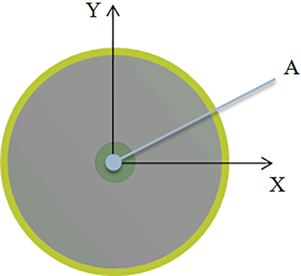
Figure 2: Control point location
3 Model Development and Validation
Using mesh methods of computer modeling implies performing a study of the mesh convergence, which consists of searching for mesh model parameters for which changing a elements number does not affect a result obtained. Since a problem being solved is multidisciplinary, a mesh convergence study for a complete computational model requires large computational costs. Therefore, the analysis was performed separately for each of subdomains (mechanical and fluid).
The convergence analysis of a rotor mesh model was performed by varying the number of elements along a shaft length. This choice is due to a fact that a disk mounted on a shaft has significant rigidity due to its geometric dimensions and does not undergo significant deformation. A geometric shaft dimensions were chosen in such a way that a rotor rigidity is low and an aeroelastic effects manifestation is more pronounced. Therefore, a rotor experiences the greatest deformation as a shaft deflection result in the radial direction. A static shaft deflection under an gravity influence and first natural bending frequency were chosen as criteria for mesh convergence. The results of a mesh model convergence analysis are presented in Fig. 3.
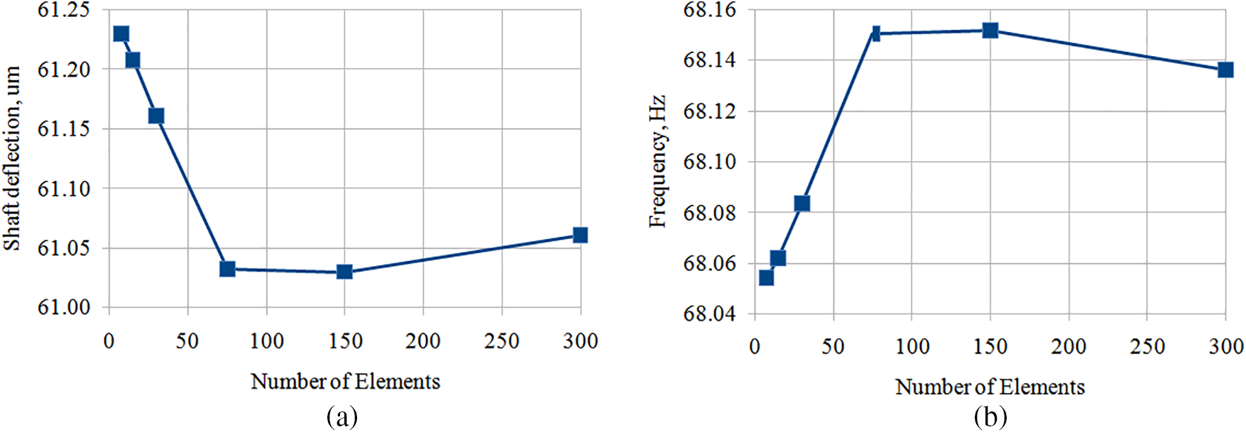
Figure 3: Mesh convergence results of a rotor model: (a) static shaft deflection (number of elements along a shaft length); (b) natural frequency (number of elements along a shaft length)
As can be seen on plots, changing elements number in a wide range along a rotor shaft length has little effect on the parameters under consideration. For all points considered, a deviation does not exceed 1%, therefore, for further calculations, an intermediate option was chosen from the considered ones-75 elements along a rotor shaft length. This choice reduces the need for computing resources and at a same time provides some margin in a solution accuracy obtained. The rotor mesh model was 7016 elements and 22,292 nodes.
Before constructing a mesh model for fluid calculations, a first layer thickness near a wall was estimated in order to obtain the dimensionless distance from a wall y +< 1 required by the selected SST turbulence model. A first layer thickness was 0.8 µm. According to the simulation results performed, a requirement for a dimensionless distance near a wall was met.
To analyze a mesh model convergence of a fluid region, a number of elements along the ring and along a gap thickness were changed. An elements number in an axial direction varied in proportion to an elements number in a circumferential direction. Since radial rotor vibrations are considered, to analyze a mesh model convergence, an inner wall of a fluid region adjacent to a rotor disk was made with eccentricity. The wall was shifted by the static rotor deflection value of 60 μm. Thus, on the inner wall, when a gas moved in a circumferential direction, a gas-dynamic force arose due to an uneven gap thickness. A gas-dynamic force magnitude was chosen as a convergence criterion. The mesh model convergence results are presented in Fig. 4.

Figure 4: Mesh convergence results of a fluid model: (a) number of elements along a ring; (b) number elements along a gap thickness
An element number in the circumferential direction was chosen to be 1500. With this value, a calculation series wasperformed with different element numbers along the gap thickness (Fig. 4b). A mesh model with 25 elements along a gap height was selected as an optimal value for further calculations. Thus, the mesh model for a fluid region was 375 thousand elements.
The resulting mesh models are shown in Fig. 5.

Figure 5: Mesh models: (a) rotor; (b) fluid
3.2 Simulation Model Validation
The selected two-way coupling between fluid and structure (2FSI) model was verified using experimental data and computational experiment results obtained in a shock tube with an installed plate, which deforms when interacting with a shock wave [24]. The experimental setup diagram is shown in Fig. 6.

Figure 6: Experimental setup with installed plate
At the beginning of the experiment, there are high and low-pressure areas in the pipe, separated by a thin membrane. At the end of a low-pressure area there is a deformable plate rigidly fixed to the base. When a threshold pressure value is exceeded, the membrane ruptures, and expansion wave, contact surface and incident shock begin to propagate in a pipe. When interacting with a wave, a plate begins to bend.
During the experiment, shadow photography of a flow and plate deformation was performed. From photographs, a movement dependence of a plate’s upper edge over time was obtained. A sensor located on a top pipe wall at a distance of 10 mm from a plate recorded pressure oscillations.
A similar numerical experiment was performed, which made it possible to perform a qualitative and quantitative comparison. Results obtained are presented in the form shadow images (Fig. 7) and plots of an upper plate edge movement, and pressure oscillations at a control point (Fig. 8).

Figure 7: Shadowgraph images in a shock tube: numerical experiment
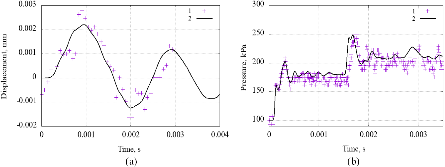
Figure 8: Upper edge movement of a plate (a) and change in pressure (b) over time: 1-natural experiment, 2-numerical experiment
In general, one can note a good agreement a plate movement calculated using an accepted model and experimental data obtained in [24].
When analyzing rotor vibrations, a key reliability criterion is a low vibration displacement magnitude. Results obtained showed a correct prediction of a structure deformation under a gas flow influence, which allows a described model to be used for vibration simulation.
The resulting trajectories of motion of a point on the rotation axis in the disk section, obtained in a computational experiment, are presented in Fig. 3.
It is clear from the figures that divergent vibrations are observed for air at 10 and 14 MPa. Moreover, at 14 MPa the vibration amplitudes are higher. At 5 and 20 MPa, steady motion is observed. At 14 MPa in 0.12 s the vibration amplitude exceeds 100 µm.
When considering methane, divergent rotor vibrations occur at a pressure of 14 MPa. The vibration increase rate is lower than for air. At time 0.12 s, the rotor oscillation amplitude exceeds 40 μm.
An increase in rotor oscillation amplitude occurs as a result of a fluid wedge interaction that occurs between a rotor and seal sleeve. Under identified conditions, a fluid wedge rotates along a circumference with a constant frequency and phase difference.
At the considered 5 and 20 MPa, a vibration is stable. At 10 MPa, oscillations with a constant amplitude of about 20 μm are observed. With a slight (5%–10%) admixture of hydrogen, a multiple decrease in the amplitude of oscillations is observed throughout the entire pressure range considered. Moreover, at a pressure of 14 MPa, the vibrations have a greater amplitude than at 5, 10, and 20 MPa.
When pumping pure hydrogen, the transient oscillation process changes qualitatively. The amplitude of the oscillations of the transient process is greater than that of mixtures No. 3 and 4. In this case, the nature of the oscillations is damped. The largest amplitude of oscillations of the transient process is observed at 5 MPa and decreases with increasing pressure.
According to Fig. 9, it can be assumed that when moving to hydrogen, the vibration frequency decreases several fold.

Figure 9: Point trajectories on the rotation axis in the disk cross section for mixtures
For further analysis, the results are summarized in the plots form of the rotor oscillation amplitudes over the initial pressure (Fig. 10).

Figure 10: Dependences of the rotor oscillation amplitudes over the initial pressure for mixtures
Fig. 4 shows that the largest vibrations amplitude is observed for an air, and the smallest for a mixture of 10% hydrogen and methane. The use of pure methane leads to greater fluctuations than with pure hydrogen and less than with air. A methane mixture with hydrogen leads to smaller fluctuations than with hydrogen.
For mixture No. 1 (air) in Fig. 11, the maximum oscillations at the initial pressure are observed at 726 Hz. For methane as a working fluid, the resonant frequency is 760 Hz. Mixture No. 5 (hydrogen) demonstrates the absence of oscillations in the high-frequency region and a shift to the low-frequency region, close to the natural frequency of the rotor.

Figure 11: Spectral composition of oscillations of rotor movements control point at an initial pressure of 14 MPa: (a) mixture 1; (b) mixture 2; (c) mixture 5
A three-dimensional numerical simulation of the compressor rotor vibrations was performed taking into account a gas-dynamic influence of a seal. The assumptions made in the model are described. An influence study of a mesh model on results obtained was carried out, and a convergence condition was achieved. The proposed numerical model was verified with experimental data, and agreement between results was obtained. A series of computational studies were carried out for various mixtures and operating pressures. For each modeled point, rotor movement trajectories were obtained, which were summarized in a plot form. From the results obtained, the following conclusions can be drawn:
1. The gas mixture composition has a significant influence on the occurrence of vibrations in labyrinth seals.
2. Hydrogen as a working fluid reduces the oscillatory amplitude.
3. Hydrogen as a working fluid increases a shaft deflection and reduces an oscillatory processes amplitude.
4. Resonance pressure weakly depends on the gas mixture composition.
Acknowledgement: None.
Funding Statement: The research was carried out with financial support from the Russian Ministry of Education and Science, Project FSNM-2023-0004 “Hydrogen Energy. Materials and Technology for Storage, Transportation and Use of Hydrogen and Hydrogen-Containing Mixtures”.
Author Contributions: The authors confirm their contribution to the paper as follows: study conception and design: Vladimir Ya. Modorskii; data collection: Ivan E. Cherepanov; analysis and interpretation of results: Vladimir Ya. Modorskii, Ivan E. Cherepanov; draft manuscript preparation: Ivan E. Cherepanov. All authors reviewed the results and approved the final version of the manuscript.
Availability of Data and Materials: Data on which this paper is based is available from the authors upon reasonable request.
Conflicts of Interest: The authors declare that they have no conflicts of interest to report regarding the present study.
References
1. Onorati, A., Payri, R., Vaglieco, B., Agarwal, A. K., Bae, C. et al. (2022). The role of hydrogen for future internal combustion engines. International Journal of Engine Research, 23(4), 529–540. https://doi.org/10.1177/14680874221081947 [Google Scholar] [CrossRef]
2. Rulev, A. V., Bakutin, P. M., Mikhailova, D. S. (2022). Analysis of the possibility of using a gas transmission system for hydrogen transportation. In: Modern problems and prospects for the development of construction, heat and gas supply and energy supply, pp. 87–90, Saratov, Russia: Saratov State Pedagogical University. [Google Scholar]
3. Polyanskiy, V., Loginov, V., Yakovlev, Y., Polyanskiy, A., Olekov, V. et al. (2023). The Metallurgical hydrogen as an indicator and cause of damage to rolled steel: Hydrogen diagnostics of fracture. Frattura ed Integrità Strutturale, 17(63), 301–308. [Google Scholar]
4. Lipiäinen, S., Lipiäinen, K., Ahola, A., Vakkilainen, E. (2023). Use of existing gas infrastructure in European hydrogen economy. International Journal of Hydrogen Energy, 48(80), 31317–31329. https://doi.org/10.1016/j.ijhydene.2023.04.283 [Google Scholar] [CrossRef]
5. Giehl, J., Sudhaus, T., Kurre, A., Mikulicz-Radecki, F., Hollnagel, J. et al. (2021). Modelling the impact of the energy transition on gas distribution networks in Germany. Energy Strategy Reviews, 38, 100751. https://doi.org/10.1016/j.esr.2021.100751 [Google Scholar] [CrossRef]
6. Fetisov, V., Davardoost, H., Mogylevets, V. (2023). Technological aspects of methane-hydrogen mixture transportation through operating gas pipelines considering industrial and fire safety. Fire: Forum for International Research in Education, 6(10), 409. https://doi.org/10.3390/fire6100409 [Google Scholar] [CrossRef]
7. Golunov, N. N., Lurie, M. V., Musailov, I. T. (2021). Transportation of hydrogen through gas pipeline in the form of methane- hydrogen mixture. Oil & Gas Storage & Transportation, 1-2, 74–82. [Google Scholar]
8. Li, L., Cao, S., Li, J., Nie, R., Hou, L. (2021). Review of rotor balancing methods. Machines, 9(5), 89. https://doi.org/10.3390/machines9050089 [Google Scholar] [CrossRef]
9. Ha, Y., Lee, Y., An, B., Lee, Y. (2023). Experiment and CFD analysis of plain seal, labyrinth seal and floating ring seal on leakage performance. Proceedings of the 11th IFToMM International Conference on Rotordynamics, vol. 139, pp. 391–405. Beijing, China. [Google Scholar]
10. Wagner, C., Tsunoda, W., Berninger, T., Thümmel, T., Rixen, D. (2019). Estimation of rotordynamic seal coefficients using active magnetic bearing excitation and force measurement. Proceedings of DINAME 2017, pp. 3–15. Cham, Springer. [Google Scholar]
11. Ur’ev, E. V., Kistoichev, A. V., Oleinikov, A. V. (2016). Eliminating the causes of low-frequency vibration failure of a magnetically suspended centrifugal supercharger. Gas Industry, 733, 102–108. [Google Scholar]
12. Childs, D. (1993). Turbomachinery Rotordynamics: Phenomena, modeling, and analysis. NY: John Wiley & Sons. [Google Scholar]
13. Paulsen, T. T., Santos, I. F., Clemmensen, L. K. H. (2023). Contribution to the estimation of force coefficients of plain gas seals with high preswirl considering rotor-foundation dynamics. Mechanical Systems and Signal Processing, 186(4), 109885. https://doi.org/10.1016/j.ymssp.2022.109885 [Google Scholar] [CrossRef]
14. Zahorulko, A., Pozovnyi, O., Peczkis, G. (2023). Experimental and CFD analysis of static and dynamic rotor stabilities in three-annular seals. Tribology International, 185, 108566. https://doi.org/10.1016/j.triboint.2023.108566 [Google Scholar] [CrossRef]
15. Yan, D., Wang, W., Chen, Q. (2020). Fractional-order modeling and nonlinear dynamic analyses of the rotor-bearing-seal system. Chaos, Solitons & Fractals, 133(7), 109640. https://doi.org/10.1016/j.chaos.2020.109640 [Google Scholar] [CrossRef]
16. Shet V. V., Sekhar A. S., Prasad B. V. S. S. S. (2020). Dynamic analysis of rotor-seal system considering the radial growth effect of the seal. Journal of Physics: Conference Series, 1510(1), 012002. https://doi.org/10.1088/1742-6596/1510/1/012002 [Google Scholar] [CrossRef]
17. Thorat, M. R., Hardin, J. R. (2020). Rotordynamic characteristics prediction for hole-pattern seals using computational fluid dynamics. Journal of Engineering for Gas Turbines and Power, 142(2), 21004. https://doi.org/10.1115/1.4044760 [Google Scholar] [CrossRef]
18. Beda, A., Simonowsky, V. (2014). Analysis of a nonlinear elastic force in a relatively long annular seal and its impact on the dynamics of the rotor. Applied Mechanics and Materials, 630, 240–247. https://doi.org/10.4028/www.scientific.net/AMM.630.240 [Google Scholar] [CrossRef]
19. Modorskii, V. Y. A., Cherepanov, I. E., Babushkina, A. V. (2021). Gas influence in gaps of labyrinth seals on the rotor dynamic state. PNRPU Aerospace Engineering Bulletin, 66(3), 106–114 (In Russia). [Google Scholar]
20. Modorskii, V. Y., Cherepanov, I. E., Babushkina, A. V. (2022). Influence of geometric, kinematic, gas-dynamic parameters on rotor dynamic state taking into account gas dynamic flow in labyrinth seals clearances. PNRPU Mechanics Bulletin, 40(4), 13–21 (In Russia). [Google Scholar]
21. Cherepanov, I. E., Modorskii, V. Y., Babushkina, A. V. (2022). Numerical investigation of rotor-dynamic system on taking into account gas in labyrinth seals clearances. Journal of Physics: Conference Series, 2308(1), 012012. https://doi.org/10.1088/1742-6596/2308/1/012012 [Google Scholar] [CrossRef]
22. Menter, F. R. (2009). Review of the shear-stress transport turbulence model experience from an industrial perspective. International Journal of Computational Fluid Dynamics, 23(4), 305–316. https://doi.org/10.1080/10618560902773387 [Google Scholar] [CrossRef]
23. Wu, L., Maillard, E., Noels, L. (2021). Tensile failure model of carbon fibre in unidirectionally reinforced epoxy composites with mean-field homogenisation. Composite Structures, 273(1), 114270. https://doi.org/10.1016/j.compstruct.2021.114270 [Google Scholar] [CrossRef]
24. Giordano, J., Jourdan, G., Burtschell, Y., Medale, M., Zeitoun, D. E. et al. (2005). Shock wave impacts on deforming panel, an application of fluid-structure interaction. Shock Waves, 14(1–2), 103–110. https://doi.org/10.1007/s00193-005-0246-9 [Google Scholar] [CrossRef]
Cite This Article
 Copyright © 2024 The Author(s). Published by Tech Science Press.
This work is licensed under a Creative Commons Attribution 4.0 International License , which permits unrestricted use, distribution, and reproduction in any medium, provided the original work is properly cited.
 Downloads
 Citation Tools