
 Submit a Paper
 Propose a Special lssue
 Open Access
ARTICLE
Study of Flow and Heat Transfer in an Ejector-Driven Swirl Anti-Icing Chamber
1 Hunan University of Arts and Sciences, Hunan Key Laboratory of Distributed Electric Propulsion Vehicle Control Technology, Changde, 415000, China
2 Liaoning Provincial Key Laboratory of Aircraft Ice Protection, AVIC Aerodynamics Research Institute, Shenyang, 110034, China
3 School of Aeronautic Science and Engineering, Beihang University, Beijing, 100191, China
* Corresponding Author: Yi Tu. Email:
Fluid Dynamics & Materials Processing 2024, 20(5), 989-1014. https://doi.org/10.32604/fdmp.2024.045624
Received 02 September 2023; Accepted 25 January 2024; Issue published 07 June 2024
 View Full Text
 Download PDF
Abstract
The formation of ice on the leading edge of aircraft engines is a serious issue, as it can have catastrophic consequences. The Swirl Anti-Icing (SAI) system, driven by ejection, circulates hot fluid within a 360° annular chamber to heat the engine inlet lip surface and prevent icing. This study employs a validated Computational Fluid Dynamics (CFD) approach to study the impact of key geometric parameters of this system on flow and heat transfer characteristics within the anti-icing chamber. Additionally, the entropy generation rate and exergy efficiency are analyzed to assess the energy utilization in the system. The research findings indicate that, within the considered flow range, reducing the nozzle specific area φ from 0.03061 to 0.01083 can enhance the ejection coefficient by over 60.7%. This enhancement increases the air circulating rate, thereby intensifying convective heat transfer within the SAI chamber. However, the reduction in φ also leads to a significant increase in the required bleed air pressure and a higher entropy generation rate, indicating lower exergy efficiency. The nozzle angle θ notably affects the distribution of hot and cold spots on the lip surface of the SAI chamber. Increasing θ from 0° to 20° reduces the maximum temperature difference on the anti-icing chamber surface by 60 K.Keywords
Nomenclature
| A | Area, m2 |
| C | Wet circumference, m |
| dh | Hydraulic diameter, m |
| G | Mass flux, kg/(m2·s) |
| h | Average heat convection coefficient, W/(m2·K) |
| H | Enthalpy, J |
| k | Thermal conductivity, W/(m·K) |
| n | Ejection coefficient |
| Nu | Nusselt number |
| P | Pressure, Pa |
| Pr | Prandtl number |
| ΔP | Pressure difference, Pa |
| Q | Heat flux, W/m2 |
| Re | Reynolds number |
| S | Entropy, J/K |
| | Entropy generation rate, W/K |
| T | Temperature, K |
| u | Velocity vector, m/s |
| X | Exergy, W |
| Greek Symbols | |
| ρ | Density, kg/m3 |
| μ | Dynamic viscosity, Pa·s |
| θ | Nozzle angle, ° |
| φ | Nozzle specific area |
| η | Exergy efficiency |
| Subscripts | |
| ave | Average |
| b | Bulk |
| eff | Effective |
| in | Inlet |
| noz | Nozzle |
| out | Outlet |
| s | Surface |
| t | Turbulent |
| w | Wall |
Aircraft engine icing is a crucial factor that affects both flight safety and aircraft performance [1]. Engines are highly susceptible to icing, and the accumulation of ice on their inlet surfaces can distort the engine’s aerodynamic shape, potentially leading to engine surges. The dislodging of ice chunks that are subsequently ingested into the engine can result in damage to the engine blades and a loss of thrust [2]. The consequences of an unanticipated failure of engine anti-icing functions in civil aircraft are of catastrophic magnitude [3]. Various anti-icing methods exist for aircraft, which can be categorized into mechanical, electric heating, and hot air heating methods based on their energy sources. Given the stringent requirements for the anti-icing performance of aircraft engines, coupled with the engine inlet’s proximity to the air source (the engine itself) which eliminates the necessity for lengthy ductwork, the utilization of hot air remains the optimal choice for engine nacelle anti-icing technology in the foreseeable future. Piccolo tubes are the most common devices for distributing hot air into the anti-icing chamber along the leading edge of aircraft engines. They utilize a pipeline with evenly spaced exhaust holes lining the chamber, releasing hot air that blows against the wall surface of the anti-icing chamber, thereby heating the lip wall surface and achieving the purpose of anti-icing.
The swirl anti-icing (SAI) system, which this paper investigates, is a recently developed technology for hot air anti-icing. Within this system, a tangential nozzle is positioned within the anti-icing chamber, injecting hot air at a specific velocity into the chamber. The nozzle operates similarly to an ejection pump within a 360° annular chamber. The circulation flow inside the chamber significantly surpasses the injected air flow, thereby enhancing convective heat transfer on the chamber’s inner wall surface. The internal circulation flow enhances the convective heat transfer of the chamber’s inner wall surface. Consequently, the leading edge of the engine’s skin is heated, achieving the purpose of anti-icing. When Compared to the piccolo tube, the swirl anti-icing technology requires only one nozzle for heat flow distribution, resulting in a reduction in system weight. This weight reduction is particularly advantageous for larger aircraft engines.
Existing research on aircraft anti-icing focuses on systems equipped with piccolo tubes, studying numerical prediction methods for the anti-icing performance and optimizing the system design to reduce the bleed air consumption. Brown et al. conducted an experimental study on the piccolo tube anti-icing (PTAI) system of the aircraft engine nacelles and proposed a heat transfer prediction correlation based on the impingement area [4]. Bu et al. conducted experimental investigations into the heat transfer characteristics from jet impingement on the inner wall surface of PTAI chambers, proposing distribution laws for stagnation point Nusselt numbers and their attenuation coefficient [5–7]. The CFD method proves effective and reliable for analyzing nacelle anti-icing system performance [8]. Guo et al. explored heat transfer characteristics of unexpanded jet impingement in a PTAI chamber, offering design requirements for the dimensionless impinging distance of the hot-air jet [9]. Pellissier et al. proposed a method for optimizing the PTAI system using the FENSAP-ICE platform and a genetic algorithm [10]. Researchers are also committed to exploring methods to enhance the heat transfer performance of hot-air jets emitted through piccolo holes. Saeed [11] conducted comparative studies using numerical simulation on various jet angles and chamber surfaces with different characteristics, such as smooth and etched surfaces. Research findings revealed that the heat transfer coefficient of the etched surface is 2–3 times higher than that of the smooth surface. Guan et al. [12] showcased through numerical research that arranging jets in an offset manner can ameliorate convective heat transfer characteristics of wedge-shaped concave surfaces. A pivotal research direction in augmenting jet impingement’s heat transfer effectiveness involves diverse nozzle designs. Notable examples encompass herringbone-shaped [13], triangular fins [14], and twisted-tape swirl jet nozzles [15], all of which have demonstrated enhanced jet heat transfer capabilities.
In 1985, Rosenthal et al. proposed a novel concept for aircraft engine anti-icing, known as SAI technology. They verified, through numerical analysis, ground experiments, flight tests, and icing wind tunnel experiments, that the SAI technology can achieve comparable performance to existing PTAI systems while boasting a simpler structure and lighter weight [16]. Subsequent to this, several studies on SAI were conducted. Chilukuri [17] scrutinized SAI performance using three distinct geometric shapes of anti-icing chambers equipped with tabbed ejector nozzles. The results suggested that the tabbed ejector nozzles did not markedly enhance the SAI chamber’s heat transfer performance. Ismail et al. [18] delved into the influence of nozzle rotation angle and specific injection area on SAI system performance across varying injection flow rates. The findings unveiled that both nozzle angle and specific injection area significantly impact the temperature distribution uniformity on the SAI chamber’s surface. Anderson [19] conducted a comparative analysis between PTAI and SAI systems, employing the CFD method. The research outcomes also demonstrated that the SAI system attains the same level of anti-icing performance as the PTAI system without necessitating additional bleed air. The few existing researches on swirl anti-icing systems only demonstrate the feasibility of swirl anti-icing systems replacing piccolo tube anti-icing systems. However, the flow and heat transfer characteristics in this 360° “closed loop” channel, as well as the improvement and optimization measures for the performance of the swirl anti-icing system, still need to be studied.
The SAI system utilizes a nozzle to provide high-velocity injection flow, propelling high-temperature air to circulate within the chamber. The high-velocity injection into the curved channel results in high-temperature fluid directly impinging upon the chamber wall, forming hot spots on the lip skin of the engine. The centrifugal effect of the annular channel flow and the local reverse pressure gradient caused by jet impingement may induce the occurrence of low-velocity areas adjacent to the channel’s inner skin, leading to cold spots on the D-chamber’s inner skin. The presence of hot spots can cause damage to nearby composite structural components, while cold spots directly impact the anti-icing performance in localized areas. The anti-icing effectiveness of the SAI system is influenced by various factors, with the design of the jet nozzle being of paramount importance. This design directly influences injection velocity and bleed pressure at the same bleed air flow rate. Furthermore, injection direction significantly affects the location of hot and cold spots, along with the uniformity of temperature distribution across the anti-icing chamber’s surface. This article aims to investigate the impact of nozzle specific area and arrangement angle on the flow and heat transfer performance of SAI chambers under varying bleed air flow rates.
The engine anti-icing chamber is a self-enclosed annular channel. High-velocity air injection drives the fluid within the chamber to circulate along the annular channel, enabling heat exchange with the inner wall of the chamber through forced convection. Simultaneously, the outer surface of the anti-icing chamber experiences forced convection heat transfer with the surrounding environment. This study considers the coupled heat transfer mechanisms encompassing the external flow field, internal flow field, and the structural characteristics of the chamber’s skin. Traditional hot air anti-icing systems employ coupled calculation methods that can be classified as tight-coupling methods [20–23] and loose-coupling methods [24–27]. In this article, the tight-coupling method is adopted, which results in an integrated mesh encompassing both internal and external domains. The calculation procedure entails the simultaneous resolution of internal and external flow fields alongside the solid’s thermal conductivity.
The numerical method employs ANSYS fluent 2022 software to compute the flow field and temperature distribution across all calculation domains. This is achieved by solving the three-dimensional, steady, and viscous Navier-Stokes equations. The turbulence model used in this study is k-omega SST. The fluid medium, air, is modeled using the ideal gas model with the Sutherland viscosity condition. The second order upwind method was specified as the spatial numerical schemes, and the SIMPLEC algorithm was used for coupling pressure and velocity.
2.1 Physical Model and Boundary Conditions
In this study, the SAI system of the aircraft engine is equipped with a constant cross-section anti-icing chamber, employing a single jet nozzle to induce circular swirling of hot air within the annular housing. The entire computational domain, illustrated in Fig. 1, comprises internal and external flow domains that are interconnected through a coupled heat transfer interface. The diameter of the nacelle measures 1.492 m, and the cross-sectional area of the D-chamber is 0.02898 m2. A total of 12 exhaust outlets, evenly distributed along the bulkhead of the chamber, possess a combined area of 0.004705 m2. The analysis in this study will encompass various nozzle specific areas (

Figure 1: Computational domain and inlet/outlet location
Table 1 furnishes the boundary conditions utilized for the SAI system analysis. Given the emphasis of this study on the influence of nozzle structure and arrangement factors upon the internal flow and heat transfer characteristics of the SAI chamber, the external environment is modeled as dry air with consistent boundary conditions.

2.2 Governing Equations and Data Reduction
The continuity, momentum, and energy equations for steady-state flow in the fluid domain are shown in Eqs. (1) to (3).
where
In the solid region, the steady-state energy transfer equation is given in Eq. (4), where
To access the overall heat transfer performance of the fluid within the anti-icing chamber, the definitions of the average thermal convection coefficients h and Nu are provided in Eqs. (5) and (6), respectively.
where
The ejection coefficient n, as defined in Eq. (8), is employed to access the ejection performance within the anti-icing chamber.
where
The nozzle specific area
Fluent meshing is employed to create the computational meshes for both the internal and external fluid domains, as illustrated in Fig. 2. Tetrahedral meshes are utilized for both domains, with shared nodes at their interface. Local mesh refinement is applied around the nozzle and its immediate surroundings. To mitigate the potential influence of mesh-related factors on the numerical analysis results, four sets of meshes were generated, comprising 3703452, 4347881, 5523134, and 6678606 cells. It was observed that once the mesh count surpassed 5.5 million, the numerical analysis outcomes for swirl anti-icing exhibited relative stability, as depicted in Fig. 3. Taking computational efficiency into consideration, a mesh size of 6 million elements was selected for the subsequent analysis.

Figure 2: Mesh model

Figure 3: Mesh independence analysis
2.4 Verification with Experimental Data
To validate the accuracy and reliability of the numerical model, a comparative analysis was conducted against experimental data [16]. The model adopted a nozzle specific area

Figure 4: Experimental validation
3 Numerical Results and Analysis
The flow and heat transfer characteristics within the annular channel, driven by the ejector, are influenced by a variety of structural factors. The outlet area of the nozzle,
3.1 Effect of
Five different
3.1.1 Effect of
Results for the circulating mass flow rate
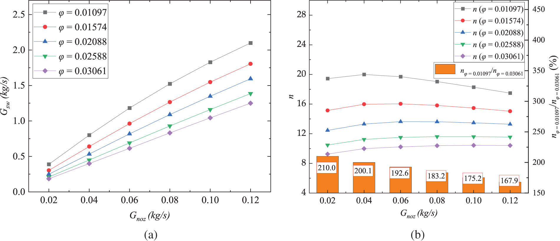
Figure 5: Effect of
Fig. 6 presents a comparison of velocity vectors in the SAI chamber across different nozzle specific areas φ. The annular anti-icing chamber features a distinctive curved flow path, leading to the high-velocity injection flow impinging on the wall.
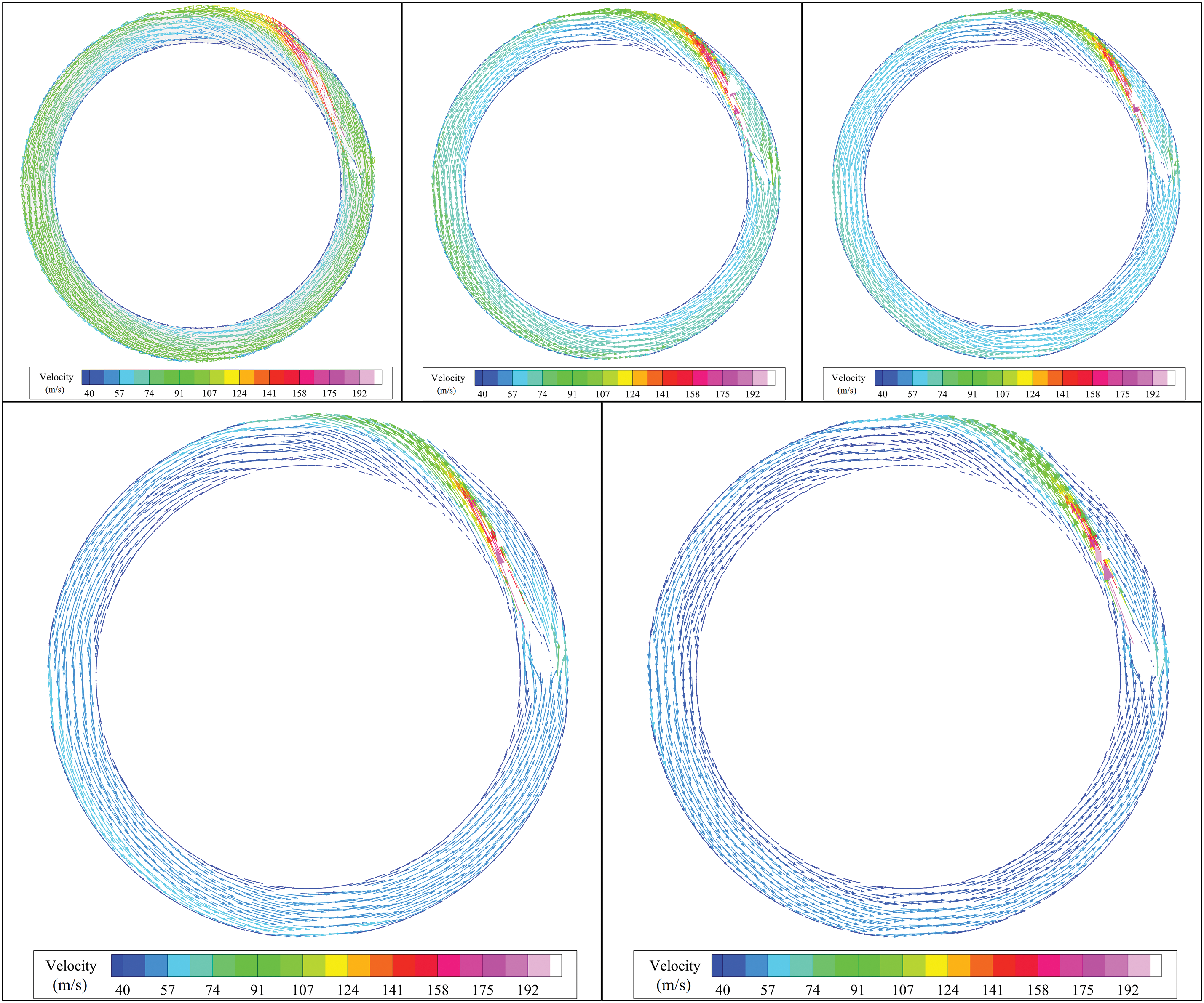
Figure 6: Velocity vector plots of the SAI chamber in different φ cases
This impingement effect becomes more pronounced with higher injection velocities. Additionally, it is noticeable that the average flow velocity within the channel exhibits a declining trend as φ increases, which is unfavorable for the overall heat transfer performance of the channel. A low-velocity region emerges adjacent to the inner skin side of the annular channel in the nozzle outlet area, rendering this region susceptible to the formation of cold spots.
Furthermore, the flow velocity along the inner skin side of the annular channel is significantly lower compared to the outer skin side. This disparity primarily stems from the inherent characteristics of the circular flow itself. Within this circulating flow configuration in the annular channel, the centrifugal effect directs the fluid toward the outer ring side of the flow passage, resulting in a low-velocity region adjacent to the inner ring side and a relatively high-velocity region neighboring the outer ring side. The diminished heat transfer capability within these low-velocity regions can consequently contribute to the formation of cold spots in these areas.
Fig. 7 showcases contour maps depicting the local pressure distribution across various nozzle specific areas φ within the cross-section of the annular channel. The graph illustrates that the heightened injection velocity attributed to the smaller nozzle specific area prompts more pronounced wall impingement. This leads to elevated local static pressure in the proximity region of the impingement surface. These localized regions of elevated pressure induce a reverse pressure gradient within the chamber, resulting in heightened flow resistance throughout the internal circulation of the entire chamber. Consequently, as the mass flow rate of the bleeding air continues to rise, the rate of ejection coefficient decline is considerably more pronounced for smaller φ values than for larger ones. This phenomenon is attributed to the positive influence of heightened injection velocity, which supplies the driving energy for internal gas circulation, being offset by the local high-pressure resistance generated by wall impingement within the channel. Exploring methods to weaken this localized resistance can help further augment the heat transfer capability of the rotating circulation within the SAI chamber.
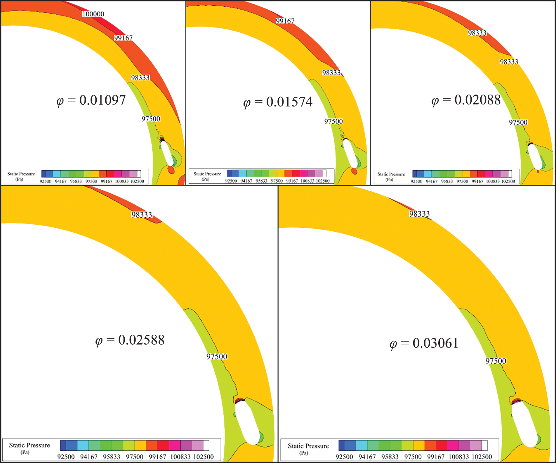
Figure 7: Contour plots of the sectional static pressure of the SAI chamber in different φ cases
3.1.2 Effect of
As depicted in Fig. 8, diminishing the nozzle specific area φ can result in the reduction of temperature for the hot spots and an increase in temperature for the cold spots on the surface of the SAI chamber. Decreasing φ has two discernible effects on the formation of hot spots. On one hand, it amplifies the injection velocity, intensifying the impact of the jet impingement on the inner surface. This, in turn, encourages the emergence of hot spots and has a detrimental effect on the uniformity of surface temperature distribution. Conversely, as φ decreases, the nozzle area diminishes, and under a constant bleed flow rate, the air pressure within the bleeding system markedly rises as shown in Fig. 9. Consequently, this prompts a more pronounced jet flow expansion phenomenon at the nozzle outlet. As a result, the temperature of the injected fluid experiences a substantial reduction as it comes into contact with the chamber’s surface.

Figure 8: Effect of
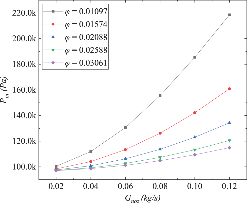
Figure 9: Effect of
Fig. 9 displays the data curve representing the requirement for bleeding air pressure in various
Fig. 10 illustrates contour maps portraying the cross-sectional temperature distribution within the annular anti-icing chamber across various φ values. It becomes evident that the impact of φ on the jet flow temperature is notably pronounced, resulting in a temperature disparity of approximately 80 K between the cases of φ = 0.01097 and φ = 0.03061. Concerning the formation of cold spots, as depicted in Fig. 8b, the reduction of φ proves advantageous in augmenting the temperature of these cold spots. As previously discussed in Section 3.1.1, the reduction of φ can enhance the ejection performance of the system. This alteration, under a consistent bleed mass flow rate, introduces greater kinetic energy to the anti-icing chamber. This energy propels the fluid within the chamber to circulate at a higher velocity, subsequently elevating the overall heat transfer performance within the SAI chamber. Additionally, this improvement extends to improve the heat transfer performance in the cold spot region on the chamber surface. Significantly, upon comparing Figs. 8a and 8b, it becomes evident that the reduction of φ results in a more substantial enhancement in elevating the temperature of cold spots as opposed to reducing the temperature of hot spots.

Figure 10: Contour plots of the sectional temperature of the SAI chamber in different
Fig. 11 illustrates the impact of φ on the maximum temperature difference between the cold and hot spots within the SAI chamber. Diminishing the bleeding air flow rate and reducing φ both contribute to a decrease in the maximum temperature difference between these regions. However, it is important to note that reducing φ comes with the consequence of heightened demand for bleeding air pressure. On the other hand, a reduction in the bleeding air flow rate results in a lower average temperature of the SAI surface, further decreasing the temperature of cold spots. Nevertheless, this strategy also raises the risk of localized ice formation. Therefore, a comprehensive trade-off assessment becomes essential to establish the optimal equilibrium between these factors, keeping in mind the constraints posed by the system design.

Figure 11: Effect of
Fig. 12 presents a contour map illustrating the distribution of lip surface temperatures within the SAI chamber. The graph reveals that the hot spots primarily manifest in the region where the high-temperature jet flow directly impinges upon the wall. Meanwhile, the cold spots predominantly emerge on the wall surface of inner ring side in the SAI chamber. Generally speaking, the temperature on the wall of outer ring side surpasses that on wall of inner ring side. This phenomenon predominantly stems from the centrifugal effect induced by the circular motion, yielding higher flow velocities and more effective heat transfer performance of the outer ring side region in the SAI chamber.

Figure 12: Contour plots of temperature distribution of the lip wall surface in different
The average surface temperature, denoted as

Figure 13: Effect of
3.1.3 Effect of
Fig. 14 illustrates the impact of
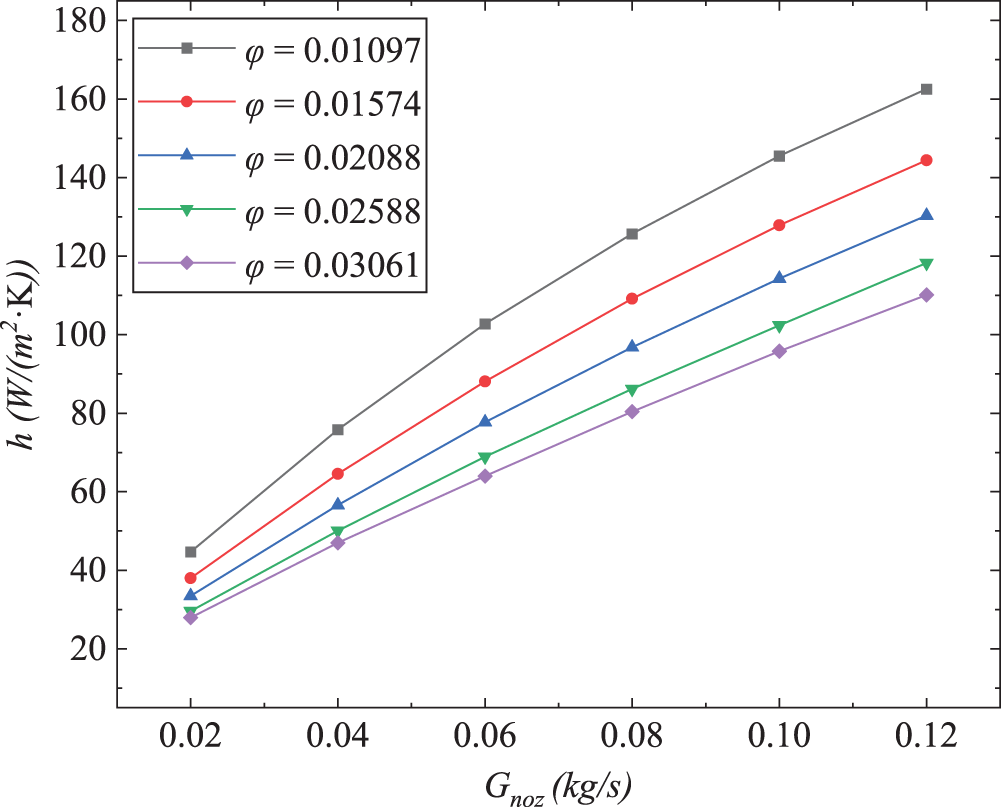
Figure 14: Effect of
In Ismail’s research [18], an empirical correlation between
Fig. 15 demonstrates the impact of
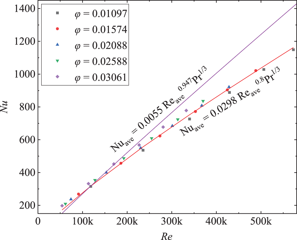
Figure 15: Effect of
Nonetheless, a certain deviation is noticeable in the high
Elevated exhaust temperature Tout signifies that the expelled gas carries a greater amount of exergy that has not been fully utilized. Fig. 16 illustrates the effect of φ on the exhaust temperature in different Gnoz conditions. The graph reveals that as φ decreases, the exhaust temperature experiences a downward trend. However, it is important to consider that a lower φ necessitates higher bleeding air pressure. This implies that more exergy is introduced into the system through bleed air. Therefore, relying solely on exhaust temperature might not effectively evaluate the exergy efficiency of the system.
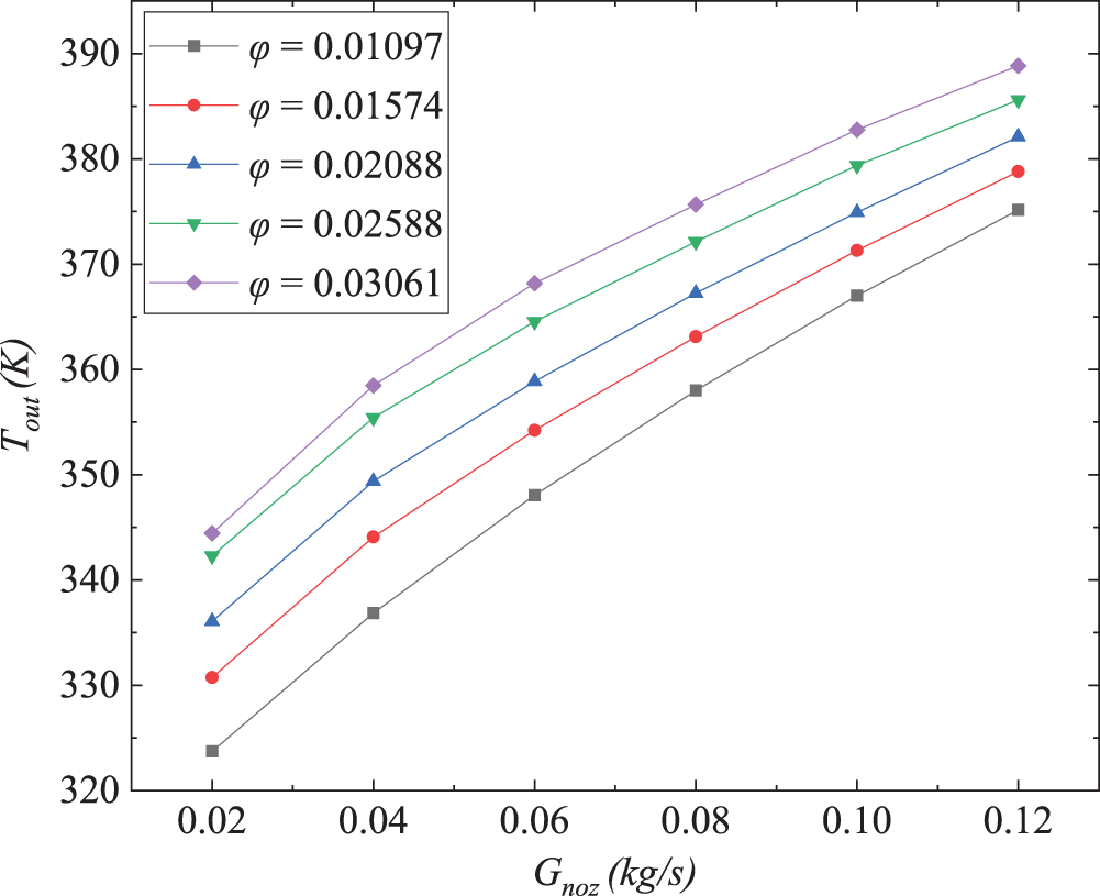
Figure 16: Effect of
3.1.4 Effect of φ on the Exergy Efficiency of the SAI System
The SAI system utilizes engine bleed air with high temperature and pressure as an energy source to heat the lip surface of the nacelle for anti-icing purposes. During the circulating process within the SAI chamber, a portion of the exergy in the bleed air is transferred to the lip wall surface and used for anti-icing purposes; a portion of the exergy is lost due to irreversible processes such as jet expansion, friction flow, and heat transfer between two sources with different temperatures; the remaining portion, along with the exhaust, is discharged into the atmosphere. In this analysis, we assume that the exhausted gas from the SAI chamber directly enters the atmosphere, leading to the complete wastage of exergy. To comprehend the extent of irreversible loss in the process and the efficiency of utilizing the available energy contained in the engine’s bleed air, we define the entropy generation rate
where
where
Fig. 17 illustrates the effect of
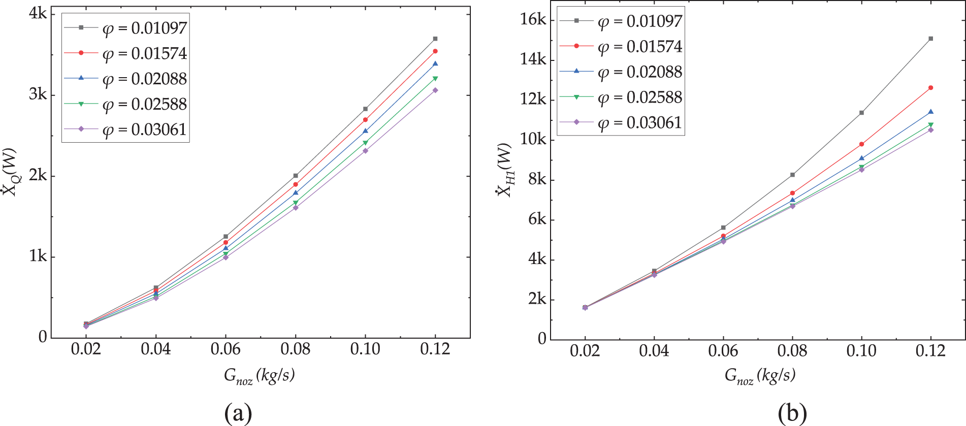
Figure 17: Effect of φ on the exergy: (a)
Fig. 18a presents the results of

Figure 18: Effect of φ on exergy efficiency: (a)
Based on the analysis in this section, reducing φ can result in improved ejection performance and enhanced heat transfer within the SAI chamber. However, this reduction also entails an increased demand for system bleed air pressure, leading to a decrease in the maximum attainable
3.2 Effect of Nozzle Angle on Flow and Heat Transfer Performance of SAI Chamber
To examine the impact of the nozzle angle θ on the flow and heat transfer performance of the SAI chamber, this analysis considers five different θ (0°, 5°, 10°, 15°, 20°) while maintaining a constant nozzle specific area φ of 0.01097. The increase in θ should ensure that the core jet zone does not directly impinge on the wall surface of the inner ring to prevent the generation of heat spots in this area. The nozzle inlet is subjected to a mass flow rate boundary spanning from 0.02 to 0.12 kg/s, and the inlet temperature is set at 533 K. The exhaust outlet of the annular channel maintains a constant pressure boundary of 96497 Pa. The external flow field employs dry air as the working fluid, featuring a velocity of 48 m/s and a temperature of −6.7 K.
3.2.1 Effect of θ on Ejection Performance
The result of the circulating mass flow rate

Figure 19: Effect of θ on ejection performance: (a)
Fig. 20 illustrates the contour plots depicting the distribution of local static pressure within the SAI chamber under various θ conditions. The high-velocity jet flow within the curved channel inevitably impinges upon the internal wall surface, resulting in localized high-pressure regions. These regions induce a reverse pressure gradient within the chamber, thus augmenting the flow resistance of the overall internal circulation. Furthermore, as the θ decreases, the proximity between the nozzle and the wall intensifies, amplifying the impingement effect and consequently elevating the local static pressure.
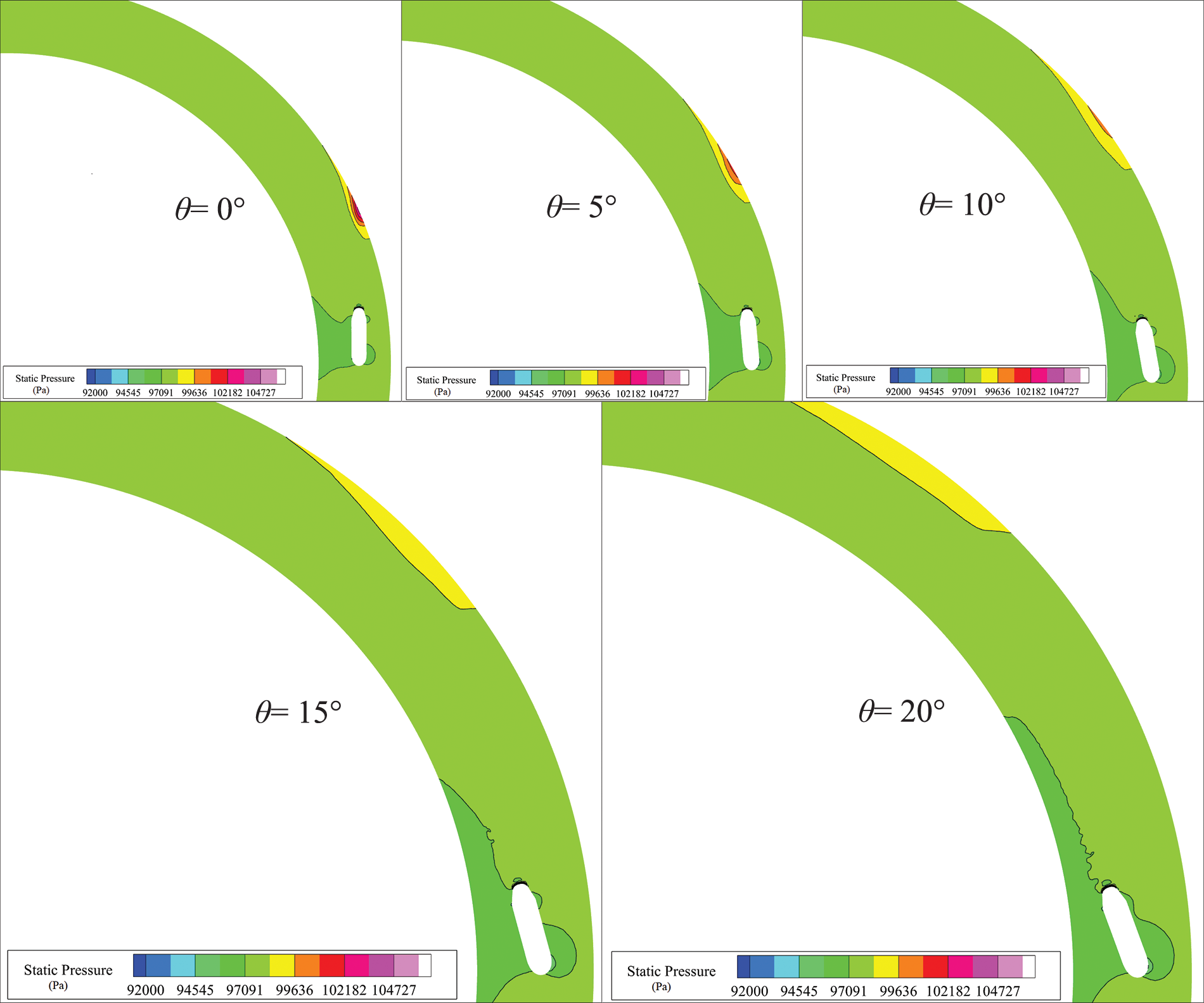
Figure 20: Contour plots of the sectional static pressure of the SAI chamber in different θ cases
3.2.2 Effect of θ on the Distribution of Cold and Hot Spots
Figs. 21a and 21b depict the maximum and minimum temperatures of hot spots and cold spots on the SAI chamber surface under various θ conditions. The analysis results reveal that an increase in θ can markedly decrease the maximum temperature of surface hot spots while concurrently raising the minimum temperature of surface cold spots. This effect contributes to enhancing the uniformity of surface temperature distribution within the SAI chamber.

Figure 21: Effect of θ on the surface maximum and minimum temperature: (a)
The enhancement of surface temperature uniformity achieved by increasing θ can be attributed to two primary factors. Firstly, the augmentation of θ leads to a notable enlargement of the distance between the nozzle outlet and the impingement region on the wall. This extended distance allows for increased mixing time between the jet fluid and the circulating flow within the chamber. Consequently, the temperature of the jet fluid reaching the wall is reduced, leading to a decrease in the temperature of the hot spots. Secondly, this increased distance allows the jet fluid for more effective momentum exchange with circulating fluid before impinging on the wall. This exchange augments the kinetic energy of the circulating flow while concurrently mitigating the intensity of the impingement effect. Consequently, the local static pressure rise in the impingement zone is reduced. This reduction in turn diminishes the localized resistance induced by the reverse pressure in the chamber, thereby fostering a higher circulating flow rate. This, in turn, contributes to the overall improvement of heat transfer performance across the SAI chamber, including the cold spot region.
As illustrated in Fig. 22, an observable trend emerges whereby augmenting θ from 0° to 20° results in a reduction of approximately 60 K in the maximum temperature disparity between cold and hot spots. This noteworthy diminution in temperature difference holds the potential to substantially ameliorate the temperature uniformity of cold and hot spots on the chamber surface of the SAI system, enhancing its anti-icing performance.
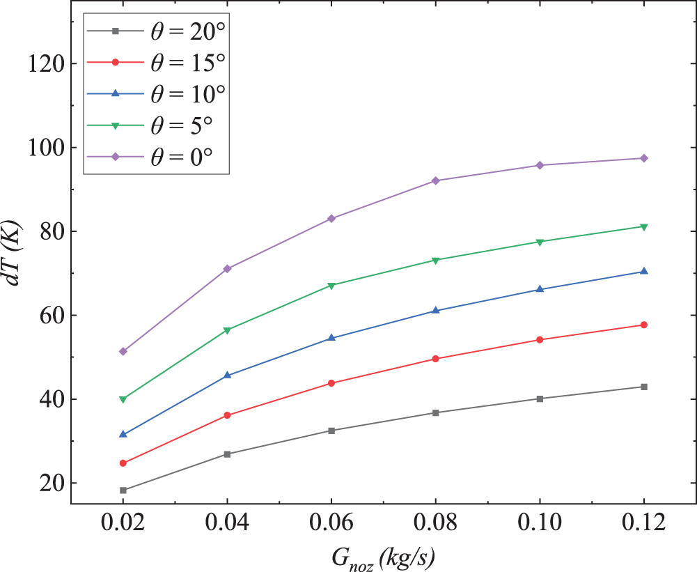
Figure 22: Effect of θ on the maximum surface temperature difference on the lip wall
Fig. 23 illustrates contour plots depicting the local sectional temperature distribution within the SAI chamber under varying θ conditions. It can be observed that the change in nozzle angle does not affect the nozzle outlet temperature. However, with the increase of θ, the distance between the nozzle outlet and the impingement region on the wall increases. Consequently, at higher nozzle angles, the impinging influence of the jet fluid on the wall surface substantially diminishes, leading to a marked reduction in the temperature of the hot spot within the impingement region, as depicted in Fig. 24. The outer-skin side of the chamber exhibits a higher temperature than the inner-skin side, because of the centrifugal effect. Increasing the nozzle angle θ can notably curtail the maximum temperature of hot spots, representing a pivotal strategy to weaken the hot spots. Furthermore, augmenting θ can also exert a positive influence on the temperature of the cold spots to a certain degree by enhancing the velocity of the mainstream flow circulating within the SAI chamber.

Figure 23: Contour plots of sectional temperature of the SAI chamber in different θ cases

Figure 24: Contour plots of lip surface temperature of the SAI chamber in different θ cases
3.2.3 Effect of θ on the Heat Transfer Performance of the SAI Chamber
The influence of nozzle angle on the average convective heat transfer coefficient of the lip wall surface is not significant as shown in Fig. 25. Although a smaller θ results in poorer ejection performance, leading to a decrease in the overall convective heat transfer performance within the SAI chamber, its local impingement effect is more significant. The convective heat transfer is enhanced within the region influenced by the jet impingement, leading to a substantial rise in local heat flux within this region. Consequently, both the area-weighted average temperature and convective heat transfer coefficient of the lip wall surface exhibit no appreciable disparities among the various θ cases.

Figure 25: Effect of θ on average convective heat transfer coefficient of the lip wall surface
Fig. 26 depicts the impact of nozzle angles θ on the internal average

Figure 26: Effect of θ on
The flow and heat transfer characteristics inside the ejection-driven SAI chamber of the aircraft engine were investigated using the CFD method, and the method was validated against experimental data. The study primarily focused on the effects of the nozzle specific area and nozzle angle on the flow and heat transfer performance inside the SAI chamber. The following conclusions were drawn:
1. Reducing the nozzle specific area φ significantly increases the ejection coefficient. Under the same bleeding mass flow rate, this enhances the circulation flow velocity inside the chamber, thereby improving the convective heat transfer performance. However, at the same time, it also substantially increases the demand for bleeding pressure.
2. From the perspective of exergy utilization, reducing φ will cause more irreversible losses to the SAI system, and the maximum achievable exergy efficiency will also decrease accordingly. Therefore, reducing φ is not beneficial for the exergy economy of the SAI system.
3. The nozzle angle θ is a crucial factor affecting the distribution of cold and hot spots on the lip surface of the SAI chamber. As the nozzle angle increases from 0° to 20°, the maximum temperature difference between cold and hot spots can decrease by nearly 60 K. Therefore, adjusting the nozzle angle is an effective approach to improve the uniformity of the surface temperature in the SAI chamber.
4. The nozzle specific area φ has little effect on the relationship between
Acknowledgement: Not applicable.
Funding Statement: This research was funded by Shenyang Key Laboratory of Aircraft Icing and Ice Protection, Grant Number XFX20220303; Education Department of Hunan Province, China, Grant Number 23A0504; National Natural Science Foundation of China, Grant Number 52275108.
Author Contributions: The authors confirm contribution to the paper as follows: study conception and design: Yi Tu; data collection: Yi Tu and Yuan Wu; analysis and interpretation of results: Yi Tu, and Yu Zeng; draft manuscript preparation: Yi Tu and Yuan Wu. All authors reviewed the results and approved the final version of the manuscript.
Availability of Data and Materials: Not applicable.
Conflicts of Interest: The authors declare that they have no conflicts of interest to report regarding the present study.
References
1. Al-Khalil, K. M., Keith, T. G., DeWitt, K. J., Nathman, J. K., Dietrich, D. A. (1990). Thermal analysis of engine inlet anti-icing systems. Journal of Propulsion and Power, 6(5), 628–634. https://doi.org/10.2514/3.23264 [Google Scholar] [CrossRef]
2. Ismail, M. A., Abdullah, M. Z. (2015). Applying computational fluid dynamic to predict the thermal performance of the nacelle anti-icing system in real flight scenarios. Indian Journal of Science and Technology, 8(30). https://doi.org/10.17485/ijst/2015/v8i30/122398 [Google Scholar] [CrossRef]
3. CAAC (2011). China civil aviation regulations. CCAR-25-R4 2011, 25.1309. https://www.caac.gov.cn/XXGK/XXGK/MHGZ/201606/P020160622405532063536.pdf (accessed on 14/03/2024). [Google Scholar]
4. Brown, J., Watterson, J. K., Raghunathan, S., Linton, A. J., Douglas, C. E. (2001). Heat transfer correlation for de-icing systems. 39th Aerospace Sciences Meeting and Exhibit, vol. 39, no. 1. Reno, Nevada, USA. https://doi.org/10.2514/6.2001-837 [Google Scholar] [CrossRef]
5. Bu, X., Peng, L., Lin, G., Bai, L., Wen, D. (2016). Jet impingement heat transfer on a concave surface in a wing leading edge: Experimental study and correlation development. Experimental Thermal and Fluid Science, 78, 199–207. https://doi.org/10.1016/j.expthermflusci.2016.06.006 [Google Scholar] [CrossRef]
6. Bu, X., Peng, L., Lin, G., Bai, L., Wen, D. (2015). Experimental study of jet impingement heat transfer on a variable-curvature concave surface in a wing leading edge. International Journal of Heat and Mass Transfer, 90, 92–101. https://doi.org/10.1016/j.ijheatmasstransfer.2015.06.028 [Google Scholar] [CrossRef]
7. Yu, J., Peng, L., Bu, X., Shen, X., Lin, G. et al. (2018). Experimental investigation and correlation development of jet impingement heat transfer with two rows of aligned jet holes on an internal surface of a wing leading edge. Chinese Journal of Aeronautics, 31(10), 1962–1972. https://doi.org/10.1016/j.cja.2018.07.016 [Google Scholar] [CrossRef]
8. Domingos, R., Papadakis, M., Zamora, A. (2010). Computational methodology for bleed air ice protection system parametric analysis. AIAA Atmospheric and Space Environments Conference, Toronto, Ontario, Canada. https://doi.org/10.2514/6.2010-7834 [Google Scholar] [CrossRef]
9. Guo, Z., Zheng, M., Yang, Q., Guo, X., Dong, W. (2021). Effects of flow parameters on thermal performance of an inner-liner anti-icing system with jets impingement heat transfer. Chinese Journal of Aeronautics, 34(9), 119–132. https://doi.org/10.1016/j.cja.2021.01.015 [Google Scholar] [CrossRef]
10. Pellissier, M. P. C., Habashi, W. G., Pueyo, A. (2011). Optimization via FENSAP-ICE of Aircraft Hot-Air Anti-Icing Systems. Journal of Aircraft, 48(1), 265–276. https://doi.org/10.2514/1.C031095 [Google Scholar] [CrossRef]
11. Saeed, F. (2008). Numerical simulation of surface heat transfer from an array of hot-air jets. Journal of Aircraft, 45(2), 700–714. https://doi.org/10.2514/1.33489 [Google Scholar] [CrossRef]
12. Guan, T., Zhang, J., Shan, Y. (2016). Convective heat transfer by a row of tab-excited impinging jets on a wedge-shaped concave surface. International Journal of Thermal Sciences, 100, 37–53. https://doi.org/10.1016/j.ijthermalsci.2015.09.015 [Google Scholar] [CrossRef]
13. Lyu, Y., Zhang, J., Liu, X., Shan, Y. (2019). Experimental study of single-row chevron-jet impingement heat transfer on concave surfaces with different curvatures. Chinese Journal of Aeronautics, 32(10), 2275–2285. https://doi.org/10.1016/j.cja.2019.07.002 [Google Scholar] [CrossRef]
14. Yu, Y., Zhang, J., Xu, H. (2014). Convective heat transfer by a row of confined air jets from round holes equipped with triangular tabs. International Journal of Heat and Mass Transfer, 72, 222–233. https://doi.org/10.1016/j.ijheatmasstransfer.2014.01.004 [Google Scholar] [CrossRef]
15. Nuntadusit, C., Wae-hayee, M., Bunyajitradulya, A., Eiamsa-ard, S. (2012). Heat transfer enhancement by multiple swirling impinging jets with twisted-tape swirl generators. International Communications in Heat and Mass Transfer, 39(1), 102–107. https://doi.org/10.1016/j.icheatmasstransfer.2011.10.003 [Google Scholar] [CrossRef]
16. Rosenthal, H., Nelepovitz, D. (1985). Performance of a new nose-lip hot-air anti-icing concept. 21st Joint Propulsion Conference, Monterey, CA, USA. https://doi.org/10.2514/6.1985-1117 [Google Scholar] [CrossRef]
17. Chilukuri, K. (2018). Ejector-driven curved duct flow and heat transfer in engine anti-icing. 2018 AIAA Aerospace Sciences Meeting, Kissimmee, Florida, USA. https://doi.org/10.2514/6.2018-0406 [Google Scholar] [CrossRef]
18. Ismail, M. A., Wang, J. (2018). Effect of nozzle rotation angles and sizes on thermal characteristic of swirl anti-icing. Journal of Mechanical Science and Technology, 32(9), 4485–4493. https://doi.org/10.1007/s12206-018-0845-x [Google Scholar] [CrossRef]
19. Anderson, M. (2019). Shielded swirl versus piccolo tube inlet thermal anti-icing system. In: Turbo expo: Power for land, sea, and air. Phoenix, Arizona, USA. V001T01A016. https://doi.org/10.1115/GT2019-90992 [Google Scholar] [CrossRef]
20. Yang, Q., Zheng, H., Guo, X., Dong, W. (2023). Experimental validation and tightly coupled numerical simulation of hot air anti-icing system based on an extended mass and heat transfer model. International Journal of Heat and Mass Transfer, 217, 124645. https://doi.org/10.1016/j.ijheatmasstransfer.2023.124645 [Google Scholar] [CrossRef]
21. Guan, T., Zhang, J., Shan, Y. (2018). Effect of offset-jets arrangement on leading edge hot-air heating effectiveness of engine inlet guide strut. Applied Thermal Engineering, 128, 357–372. https://doi.org/10.1016/j.applthermaleng.2017.09.040 [Google Scholar] [CrossRef]
22. Yang, Q., Guo, X., Zheng, H., Dong, W. (2023). Single- and multi-objective optimization of an aircraft hot-air anti-icing system based on Reduced Order Method. Applied Thermal Engineering, 219, 119543. https://doi.org/10.1016/j.applthermaleng.2022.119543 [Google Scholar] [CrossRef]
23. Bu, X., Lin, G., Shen, X., Hu, Z., Wen, D. (2020). Numerical simulation of aircraft thermal anti-icing system based on a tight-coupling method. International Journal of Heat and Mass Transfer, 148, 119061. https://doi.org/10.1016/j.ijheatmasstransfer.2019.119061 [Google Scholar] [CrossRef]
24. Guo, Z., Guo, X., Yang, Q., Dong, W. (2022). Heat transfer characteristics of unexpanded jet impingement in piccolo hot air anti-icing chamber. Applied Thermal Engineering, 200, 117540. https://doi.org/10.1016/j.applthermaleng.2021.117540 [Google Scholar] [CrossRef]
25. Yang, Q., Guo, X., Dong, W., Wang, A. (2022). Ice accretion and aerodynamic effects on a turbofan engine nacelle under takeoff conditions. Aerospace Science and Technology, 126, 107571. https://doi.org/10.1016/j.ast.2022.107571 [Google Scholar] [CrossRef]
26. Chauvin, R., Villedieu, P., Trontin, P., Bennani, L. (2014). A robust coupling algorithm applied to thermal ice protection system unsteady modeling. 6th AIAA Atmospheric and Space Environments Conference, Atlanta, GA, USA. https://doi.org/10.2514/6.2014-2061 [Google Scholar] [CrossRef]
27. Carozza, A., Petrosino, F., Mingione, G. (2022). Numerical procedure for the simulation of an electro-thermal anti-icing system. Aircraft Engineering and Aerospace Technology, 94(8), 1433–1448. https://doi.org/10.1108/AEAT-07-2021-0222 [Google Scholar] [CrossRef]
Cite This Article
 Copyright © 2024 The Author(s). Published by Tech Science Press.
This work is licensed under a Creative Commons Attribution 4.0 International License , which permits unrestricted use, distribution, and reproduction in any medium, provided the original work is properly cited.
 Downloads
 Citation Tools