
 Submit a Paper
 Propose a Special lssue
 Open Access
ARTICLE
A Study on the Performances of Solar Air Collectors Having a Hemispherical Dimple on the Absorber Plate
1 School of Architecture and Environmental Engineering, Zhengzhou Technical College, Zhengzhou, 450121, China
2 School of Mechanical and Power Engineering, Zhengzhou University, Zhengzhou, 450001, China
* Corresponding Author: Xinli Wei. Email:
Fluid Dynamics & Materials Processing 2024, 20(5), 939-955. https://doi.org/10.32604/fdmp.2023.043614
Received 07 July 2023; Accepted 12 December 2023; Issue published 07 June 2024
 View Full Text
 Download PDF
Abstract
In order to increase the efficiency of solar air collectors, a new variant with a protrusion is proposed in this study, and its performances are analyzed from two points of view, namely, in terms of optics and thermodynamics aspects. By comparing and analyzing the light paths of the protrusion and the dimple, it can be concluded that when sunlight shines on the dimple, it is reflected and absorbed multiple times, whereas for the sunlight shining on the protrusion, there is no secondary reflection or absorption of light. When the lighting area and the properties of the surfaces are the same, the absorption rate of the dimple is 10.3 percentage points higher than that of the protrusion. In the range of Reynolds number from 3000 to 11000, numerical simulations about the effects of the relative height (e/Dh = 0.033–0.1) and relative spacing (p/e = 4.5–8.5) of protrusions on air heat transfer and flow resistance show that, in terms of comprehensive evaluation coefficient (PF), the best relative height is 0.085, when the relative spacing is 5. A correlation of Nu and f with Re, e/Dh and p/e is obtained by linear regression of the results, in order to provide a useful reference for the design and optimization of this kind of solar air collector.Keywords
With the lack of energy sources and the deterioration of the environment, People are increasingly concerned about the application of renewable energy. Solar energy is favored as the cheap and clean energy. Solar air collector is one of the most convenient and simple applications for utilizing solar energy. It is widely used in heating, industrial drying and other fields [1].
In the research of common plate heat exchangers, the heat transfer enhancement technology of convex cell plates first appeared in the former Soviet Union in the 1980s. The structure can exchange for a greater enhanced heat transfer effect at the cost of less resistance [2–4], it is used to strengthen heat transfer inside the tube, rotating channel and plate heat exchanger. Brij et al. [5] analyzed and summarized multiple methods to improve the heat transfer characteristics of solar air collectors with flat plates. Adding a convex cell structure on the absorber plate is one of the effective methods to strengthen heat exchange between the absorber plate and air. For example, Sang et al. [6], Wu et al. [7], Yu et al. [8] and Jiang [9] studied the convex cells of the spherical crown structure on the plate. Liu et al. [10] and Zhang et al. [11] studied the heat transfer performance of similar convex cell plates such as ellipsoid or embedded spherical concave structures.
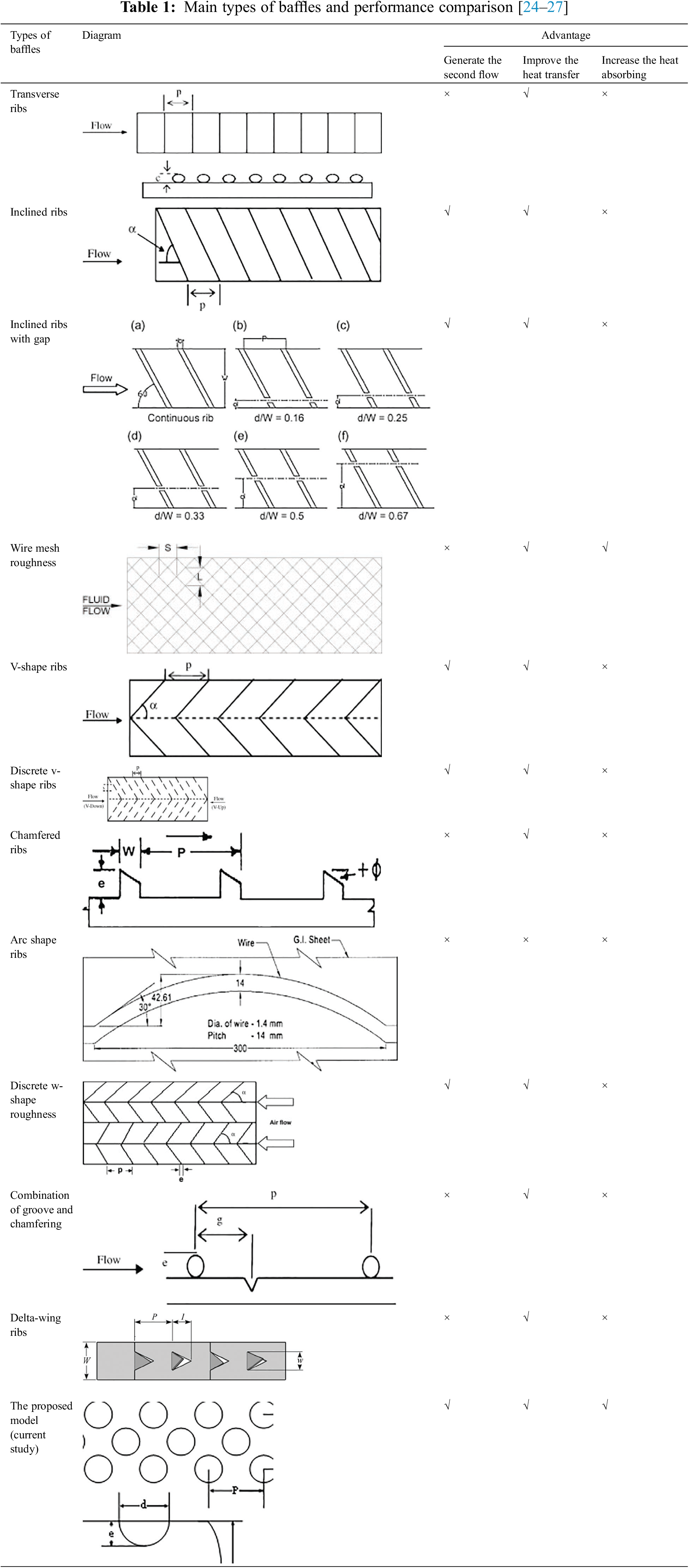
The structure of the absorber plate of the solar air collector is similar to the plate of the heat exchanger. Therefore, many scholars have discussed the heat transfer properties of absorber plates with convex cells and pit structures. Saini et al. [12] and Kishor et al. [13] researched the heat transfer intensify effect of the heat collecting plates with square pits by experiment. Bhushan et al. [14] experimentally investigated the heat transfer enhancement effect of spherical crown convex cell plates in diamond arrangement. Yadav et al. [15] and Zeynep [16] explored the heat transfer enhancement effect when the spherical crown convex cells are arranged in a circular arc. Muneesh et al. [17] studied the heat transfer enhancement effect of convex cells in arc arrangement. They all obtained the correlation of Nusselt number, resistance coefficient and corresponding geometric parameters under specific structure and arrangement. Kumar et al. [18] projected and manufactured a combination of concave and convex roughness elements on the absorption plate. Aman et al. [19] reviewed the geometric structures of concave and protruding roughness used in SAHs catheters, as well as the correlations between Nu and f. Navneet et al. [20] used micro shapes of different shapes and pits on absorption plates for solar air heaters (SAH) to improve heat transfer. Zhu et al. [21] proposed the numerical simulation and experimental results of a micro heat pipe array flat solar collector. Seyfi et al. [22] presented a comparison of flexible aluminum foil tube solar air collectors and conventional flat plate collectors. Subhash et al. [23] studied the improvement of the thermal performance of solar air heaters by using a louvered fins collector. And the primary pattern and the performance comparisons of the solar air collector system are shown in Table 1.
At present, the research on the absorption plate of solar air collectors mainly focuses on the spherical crown structure and only on the aspect of thermal performance. There is little research on the optical performance of hemispherical convex cell collectors. However, the research of this research group shows that the hemispherical structure can make the sunlight reflect and absorb multiple times in the dimple [28], which can effectively improve the sunlight absorption rate compared with the spherical crown structure. Therefore, the performance of solar air collectors with hemispherical dimples on the absorber plate is studied from two points of view, namely, in terms of optics and thermodynamics aspects in this paper, which can provide a reference for subsequent engineering applications.
CFD software package was used to simulate the flow of the absorber plate with hemispherical protrusion artificial roughness. In order to ensure better grid quality, the hexahedral grid is used to divide the computing domain, the boundary layer grid is appropriately encrypted, and the grid independence is checked. The solar air collector consists of air channels with a size of 1950 mm × 950 mm × 50 mm. The protrusion on the absorber is hemispherical, and the back of the protrusion is dimple which is shined by solar radiation. Because the flow channel between the absorber plate and the bottom plate is periodic change, the periodic model is used to simulate the model, and the height of the flow channel in the model is kept constant, and the geometry model and material object are shown in Fig. 1.
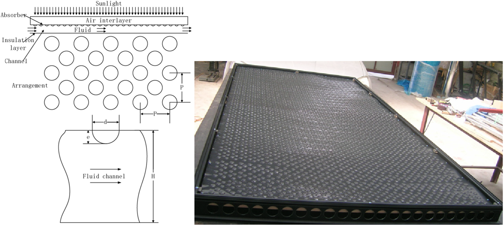
Figure 1: Geometry model and material object
Due to the computational domain being relatively rules, the hexahedral grid is used to mesh the computational domain and the boundary layer is properly encrypted in order to ensure a better quality of the grid. Grid partitioning is shown in Fig. 2a. Wall face adopts the enhanced wall function method, the border of both sides is the symmetry plane, the surface of the absorber plate having the protrusion is a constant heat flux and the inflow and outflow surface is periodic boundary conditions. The details of the boundary conditions are shown in Fig. 2b.
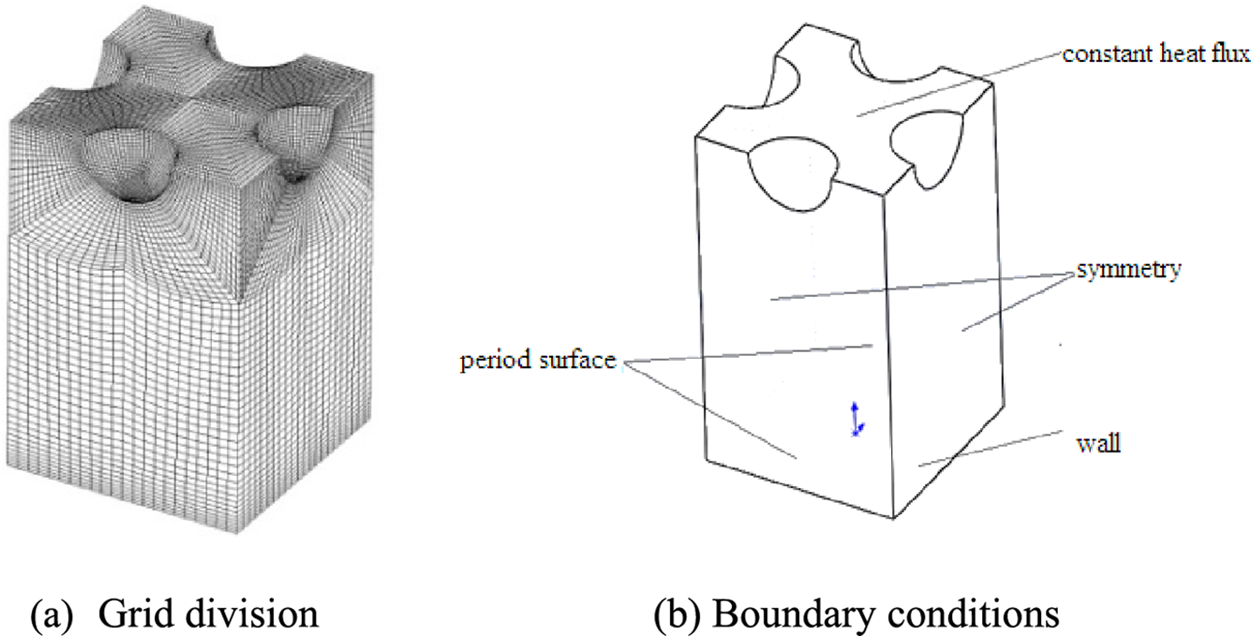
Figure 2: Mesh and boundary conditions
In general, the larger the number of grids in the model, the more accurate the simulation calculation results. However, an excessive number of grids will increase the computational workload. Therefore, an independent assessment of the number of grids is conducted to find the optimal number of grids that can not only ensure accuracy but also reduce computational complexity. The following is an investigation of the changes in Nu and f of the convex cell collector plate surface under different mesh numbers in the model, as shown in Fig. 3. When the number of grids is around 100000, increasing the number of grids results in almost no changes in the Nu and f of the convex cell collector plate. Therefore, a grid quantity of 100000 can meet the calculation accuracy requirements, and 100000 is selected as the grid quantity for subsequent simulation.
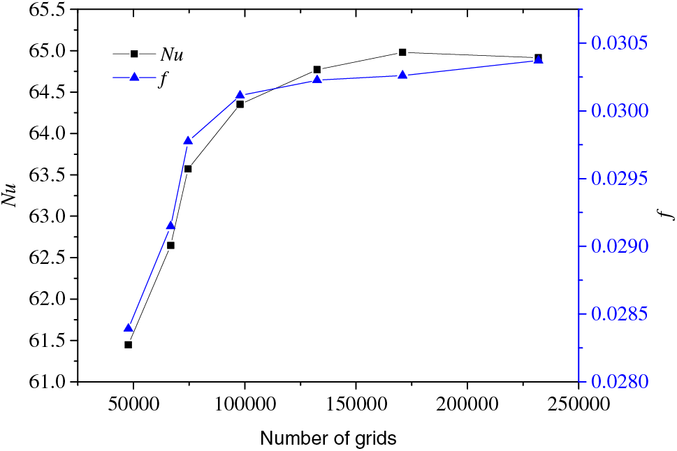
Figure 3: Grid independence assessment
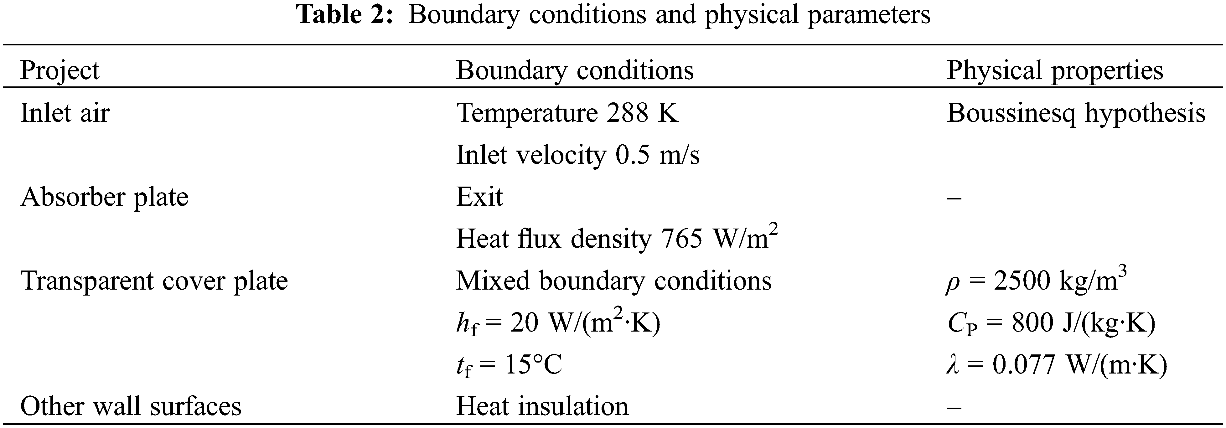
The internal flow of the collector is approximated as pipeline flow. Due to turbulent internal flow, turbulence model selects Realizable k-ε. Due to the dominance of convective heat transfer, the radiation heat transfer is not considered in the simulation. Due to the low internal air flow rate, it can be regarded as an incompressible fluid, but the temperature change is significant, resulting in a change in density. Therefore, the Boussinesq hypothesis is adopted. Pressure interpolation scheme is second order, the discretization format for the convection term is second-order upwind, while the discretization format for the diffusion term is first-order upwind, using the Simple algorithm [29] and energy equation residual value is decreased to 1 × 10⁻⁶ and the rest of the residual value is decreased to 1 × 10⁻⁵, and the averaged Nusselt numbers of the absorber plate surface is unchanged with iteration. Due to the 45° angle between the placement of the collector and the water level, the influence of buoyancy should be taken into account when calculating. The boundary conditions and physical properties of the inlet and outlet, collector plate, surrounding maintenance structure, and glass cover plate are shown in Table 2.
The optical path of protrusion and dimple is simulated by TracePro optical simulation software. The size of protrusion and dimple is the same, which the section diameter is 10 mm, so as to ensure the same daylighting area, surface properties and light source settings.
In an effort to research the heat transfer, resistance and comprehensive performance between hemispherical protrusion absorber plate and air, the heat transfer Nu, the friction factor f and the comprehensive performance parameters PF of hemispherical protrusion absorber plate are compared with those of ordinary flat plate.
The Nusselt number Nu is defined as:
The friction factor f is defined as:
The comprehensive performance parameters PF is defined as:
where α is the heat transfer coefficient, l is the characteristic length (take 2 times of the height of the runner), λ is the thermal conductivity of air,
According to the GB 26976-2011 requests, the parameter range covered in this study is as follows:
(1) The Reynolds number is between 3000 and 11000.
(2) The relative roughness height is 0.033 to 0.1.
(3) The relative roughness pitch is 4.5 to 8.5.
The optical path simulation results of dimple and protrusion are shown in Fig. 4, and the comparison of absorption rate results is shown in Fig. 5. It can be seen that red represents incident light and blue represents reflected light. When the sunlight shines on the dimple, the maximum intensity is 8.9316e+007, the average intensity is 7.445e+006, the total flux is 543.2 w and the incident rays is 1035, so the light is reflected and absorbed for many times, While sunlight shines on protrusion, the maximum intensity is 2.5138e+007, the average intensity is 4.7572e+006, the total flux is 472 w and the incident rays is 590, the light does not undergo secondary reflection and absorption. It is assumed that the absorptivity of surface properties is 0.80, while the actual absorptivity of dimple is 0.903, which is increased by 10.3 percentage points. The actual absorptivity of protrusion is still 0.80, that is, light is not reflected and absorbed many times.
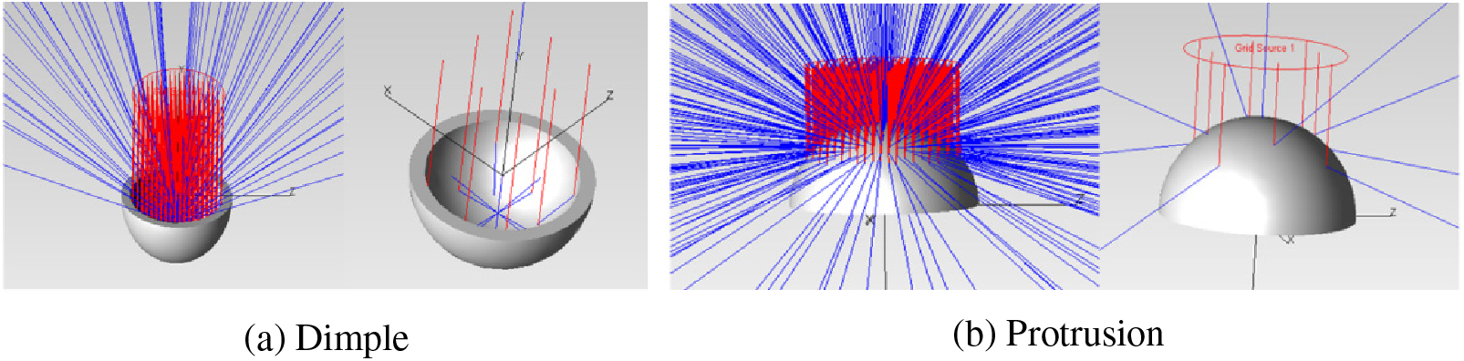
Figure 4: Light path shining on dimple/protrusion
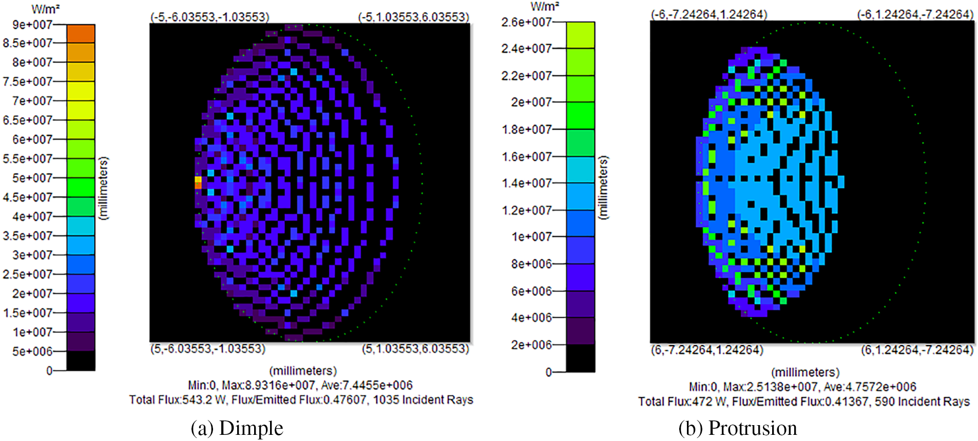
Figure 5: Radiation flux distribution on dimple and protrusion
The optical path simulation results of the hemispherical and spherical cap dimple are shown in Fig. 6, and the comparison of absorption rate results is shown in Fig. 7. It can be seen that when the sunlight shines on the hemispherical dimple, more light is reflected and absorbed multiple times than on the spherical crown. When the absorptivity of the same daylighting area and the set surface attribute is 0.80, the actual absorptivity of the hemisphere is 0.926, which is 2 percentage points higher than that of the spherical crown, while the actual absorptivity of the spherical crown is 0.906. In other words, the reflection and absorption effect of the hemisphere is better than that of the spherical crown. From optical analysis, the absorption rate of hemispherical dimple is the highest. It is recommended to use hemispherical dimple to ensure maximum absorption of solar radiation.
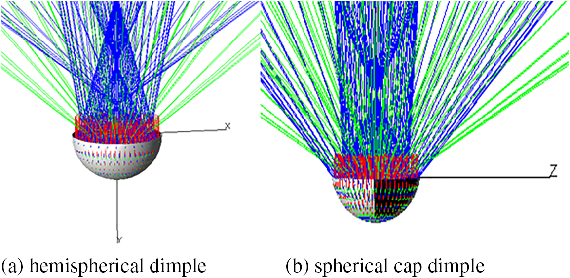
Figure 6: Schematic diagram of light path on hemispherical and spherical cap dimple
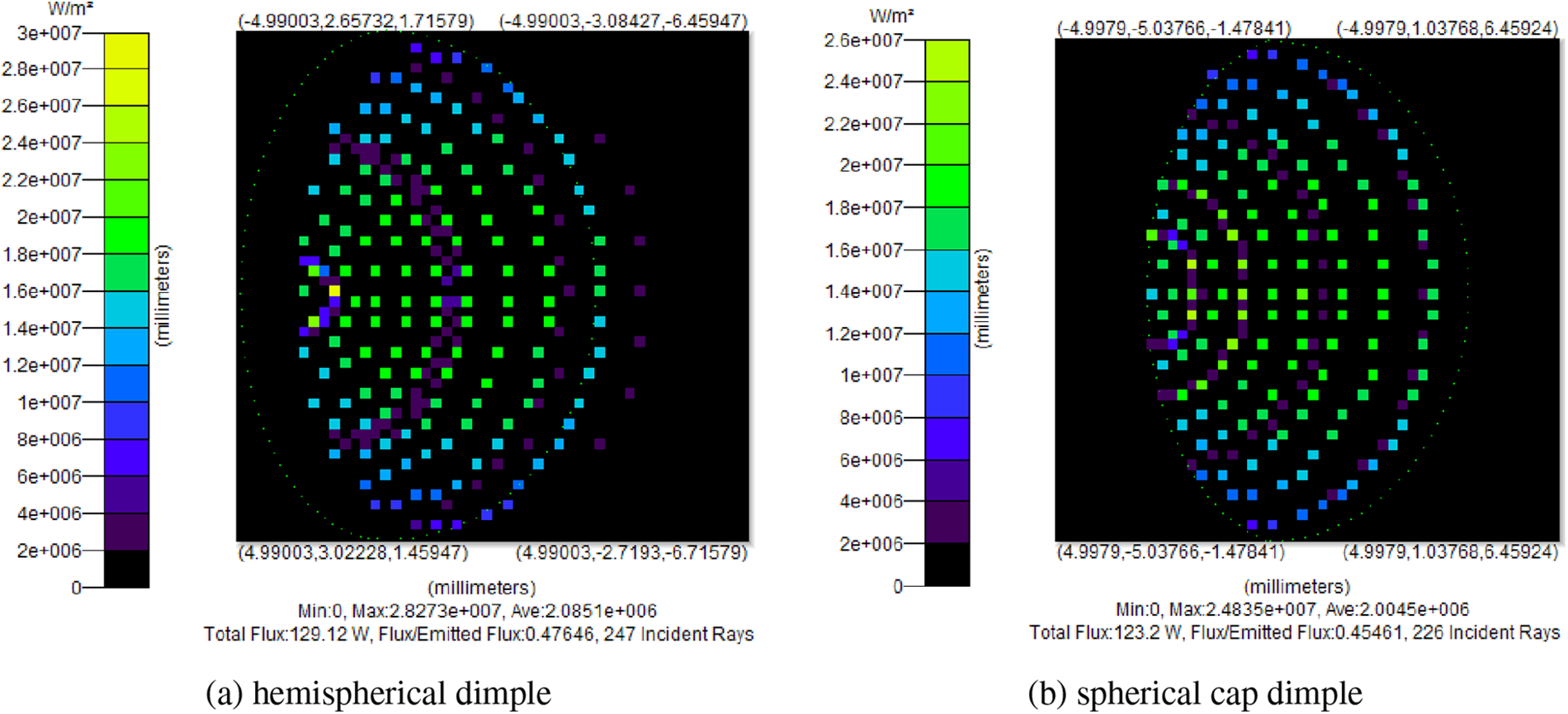
Figure 7: Radiation flux distribution on hemispherical and spherical cap dimple
The flow channel of air flowing through dimple and protrusion is simulated and analyzed by fluent simulation software. The sizes of dimple and protrusion and the simulation parameters are the same. The simulation results are shown in Fig. 8. It can be seen from the figure that the protrusion can destroy the bounding layer of the fluid flow and enhance thermal transmission between the absorber plate and the fluid, when the fluid flows through the protrusion. When the fluid flows through the dimple, the fluid forms a dead zone at the bottom of the dimple, which leads to the local temperature rise and the heat transfer efficiency decrease. From the above analysis, it can been drawn such a conclusion that facing the sun is hemispherical dimples to maximize the absorption of solar radiation; The protrusions in contact with the air can destroy the boundary layer of air flow and improve the heat transfer efficiency.
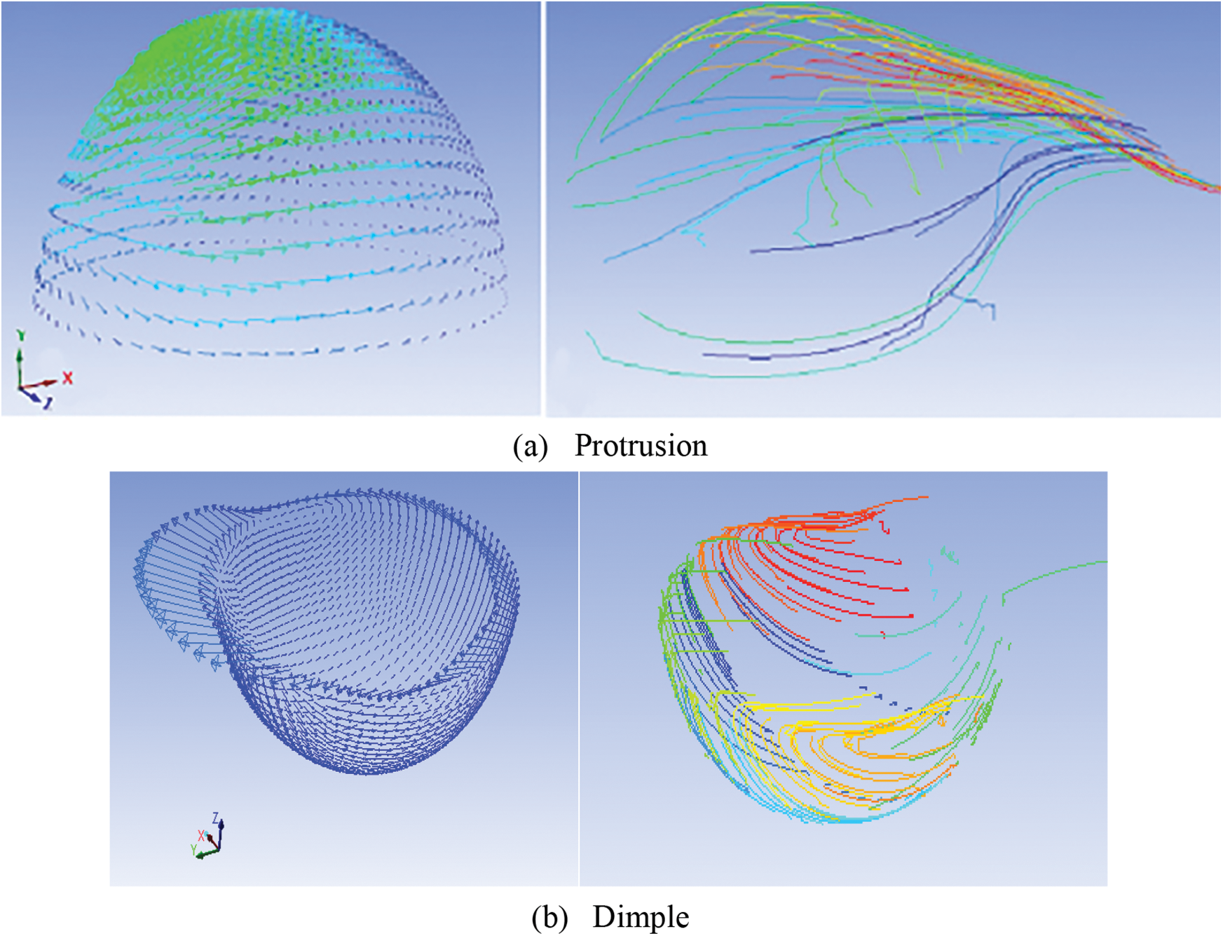
Figure 8: Streamline simulation on dimple and protrusion
The heat transfer characteristics of the hemispherical protrusions are discussed in Figs. 9 and 10. It can be seen that the vortex area generated by the fluid flowing through the hemispherical protrusions is larger than that generated by the fluid flowing through the spherical cap. When the fluid traverses the protrusions, the anterior is the low temperature area, and the back side is the high temperature area, mainly because the front side directly collides with the fluid head-on, so the heat transfer is more sufficient, while in the back side there is a vortex, and the flow velocity decreases, resulting in the temperature increase. On the whole, the temperature of the hemispherical protrusions surface is lower than that of the spherical cap, indicating that the heat transfer of the fluid flowing through the hemispherical protrusions is more sufficient.
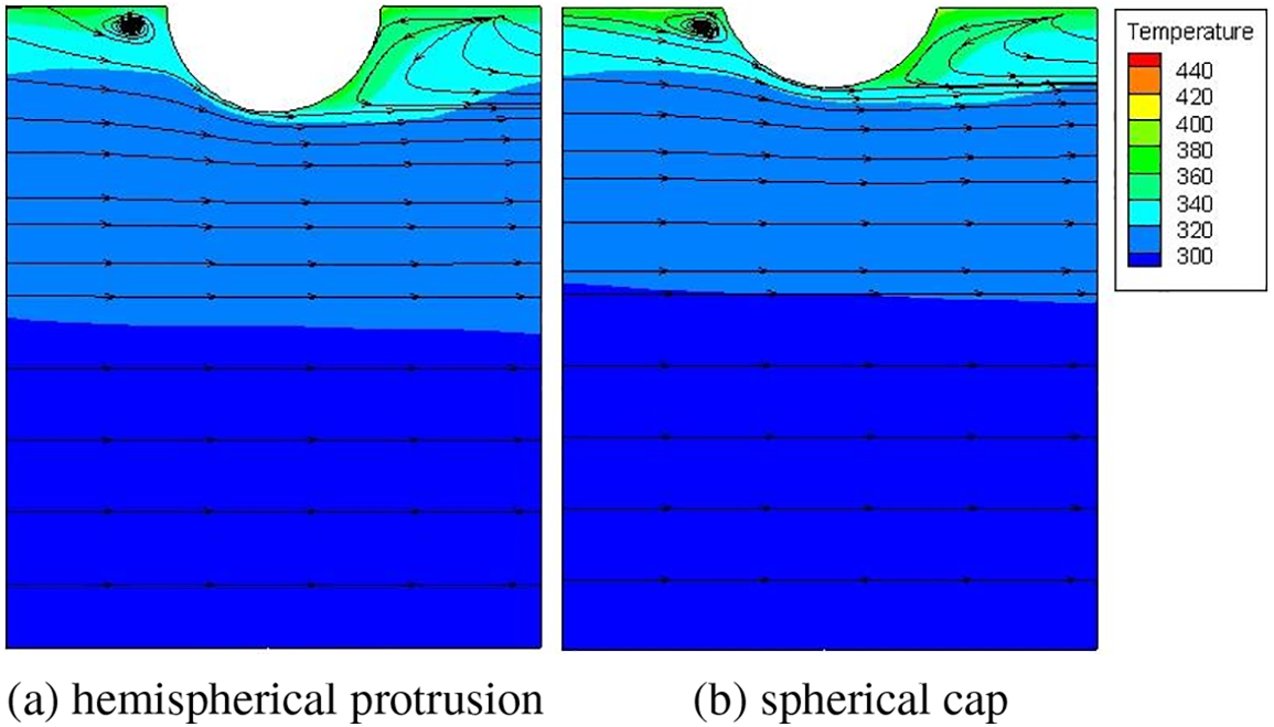
Figure 9: Comparison of streamline and temperature distribution
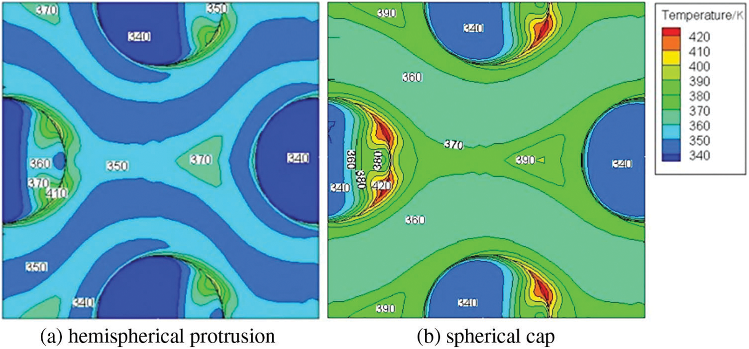
Figure 10: Temperature distribution on protrusion surface
Table 3 is the comparison for performance parameters of air flowing through hemispherical protrusion and spherical cap, which have the same section size but different shape. It can be seen from the table that at the same Re, the Nu of fluid flowing through hemispherical protrusion is larger than that of spherical cap, and the corresponding pressure drop and resistance coefficient are also larger. When the Re is less than 7000, PF is greater than 1. When the Re is greater than 9000, PF is less than 1. Considering the high absorptivity, the hemispherical protrusions are used.
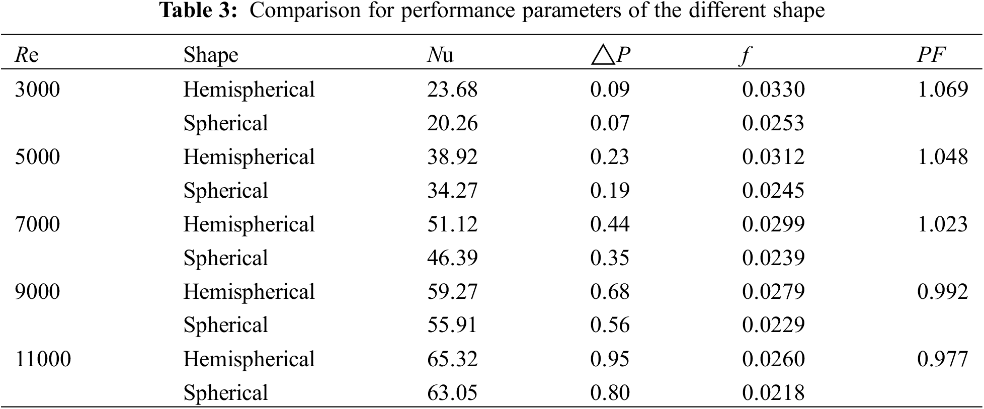
Fig. 11 shows the streamline and temperature distribution of the symmetry plane at different relative heights when the relative spacing is 5. It can be seen from the figure that the hemispherical protrusion has a disturbance effect on the air flowing through, especially on the windward front side and the leeward side. As the hemispherical protrusion larger, the flow disturbance intensity in the channel becomes larger, so the heat transfer effect is better.
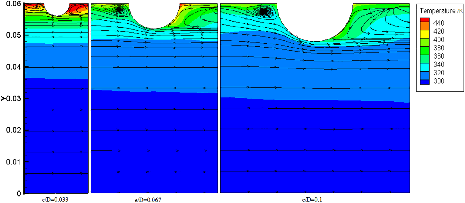
Figure 11: Streamlines and temperature distribution on the symmetry plane (Re =7000)
Fig. 12 shows the temperature distribution on the surface when Re = 11000 and e/D = 0.066~0.1. It can be seen from the figure that when e/D = 0.1, the temperature directly behind the hemispherical protrusion is higher than that of e/D = 0.083. As the hemispherical protrusion becomes larger (the relative height becomes larger), the transverse pressure perpendicular to the flow direction is not enough to make the mainstream on both sides of the hemispherical protrusion converge, so that the flow dead zone area directly behind the protrusion expands, resulting in the heat transfer weakening.
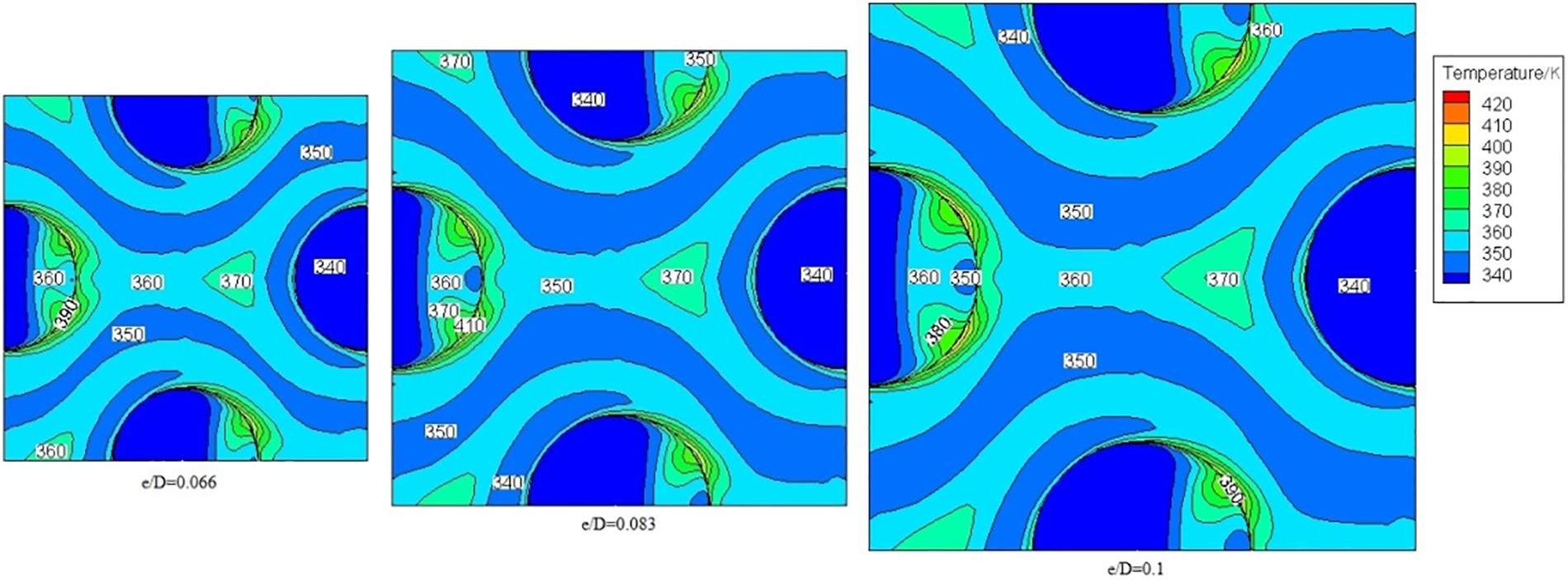
Figure 12: Temperature distributions on protrusion surface (Re = 11000, p/e = 5)
So as to comprehensively assess effectiveness of hemispherical protrusion on heat transfer, the comprehensive performance parameters PF is investigated, as shown in Fig. 13. It can be seen that the PF first enlarges and then reduces with the enhancement of Reynolds number, but in different Re regions, the position of PF extremum is also different, and with the increase of Re, the extremum point shifts to the right. Considering the Re in the range of 3000–10000, when p/e is 5, the best relative height is 0.083.
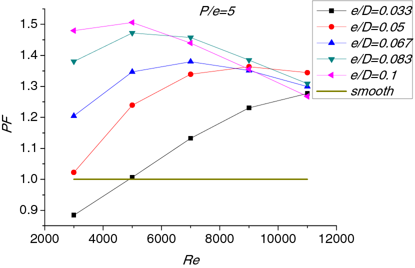
Figure 13: Variation of PF for different values of e/D
Fig. 14 shows the temperature distribution of different p/e when e/D = 0.067. It can be seen that a hemispherical protrusion has a certain range of disturbance, at the same Re and e/D. When p/e is small, the disturbance areas of adjacent protrusion overlap. In addition, if the adjacent protrusions are too close, the flow dead zone between protrusions is easy to form, so the heat transfer effect is poor. However, when the p/e is larger than the effective disturbance range of the protrusion, there is a region where the heat transfer is not enhanced, which also weakens the heat transfer enhancement effect to a certain extent. Therefore, when the p/e ratio of protrusion is right, there is no dead zone and overlap, the heat transfer effect is the best.
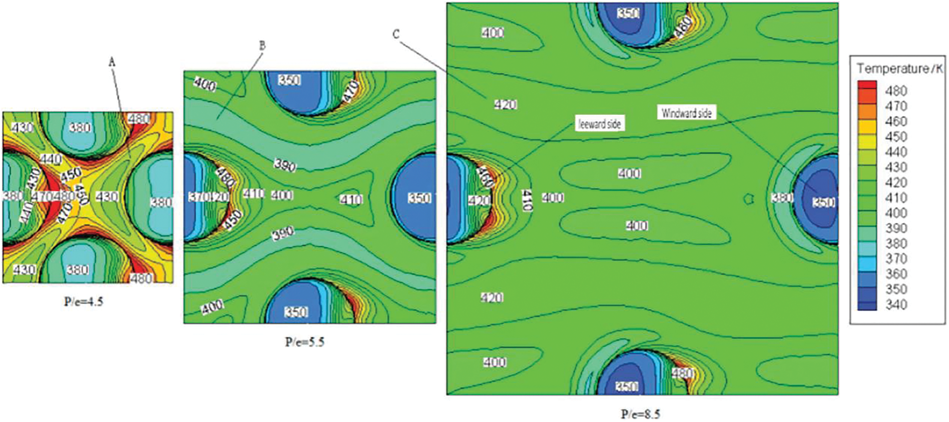
Figure 14: Temperature distributions on protrusion surface (Re = 5000, e/D = 0.067)
The influence of relative spacing (p/e) on the comprehensive coefficient PF is shown in Fig. 15. It can be seen that when 5000 < Re < 9000 and the relative spacing (p/e) is equal to 5.5, the PF is the largest. Under the same p/e and e/D conditions, PF grows first and then reduces slightly with the enhancement of Reynolds number. This is because the dead zone of flow decreases and the heat transfer effect increases obviously with the increase of Reynolds number. However, with the increase of Reynolds number, the dead zone does not decrease obviously, but the resistance increases greatly, the PF increases first and then decreases.
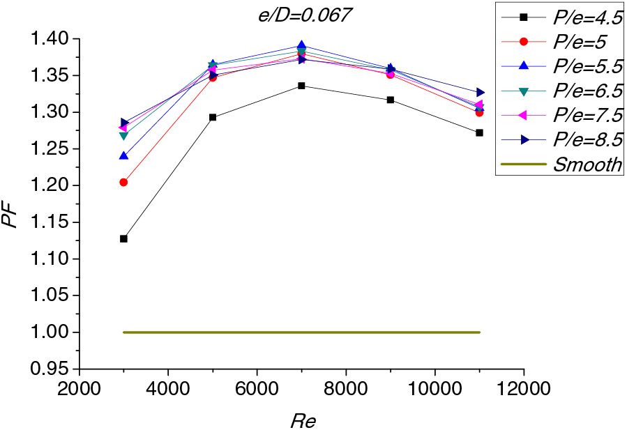
Figure 15: Variation of PF for different values of p/e
Fig. 16 is the comparison of simulated to experimental results. It can be seen from the figure that the experimental test results are basically consistent with the numerical simulation results, and the maximum relative error between the numerical simulation results of air outlet temperature and the experimental test results is 10.6%. Therefore, the model can well forecast the function of the air collector.
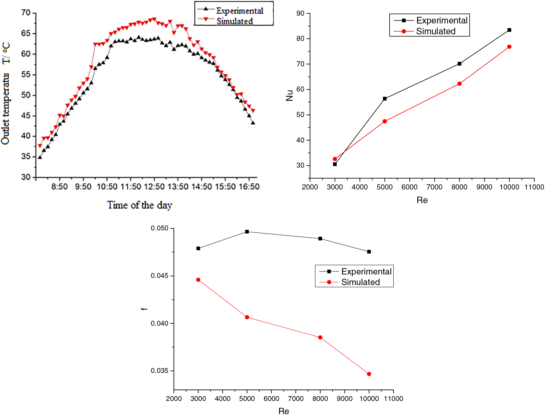
Figure 16: Comparison of simulated to experimental results of outlet temperature with time
5 Correlations for Nusselt Number and Friction Factor
For the convenience of research, the numerical simulation results are nonlinear regressed to obtain the correlation between Nu and f on Re, p/e and e/D. The functional relationships for Nu and f can therefore be written as:
Plot all data points of Nu according to Reynolds number, Nusselt number and Reynolds number are nearly linear relationship. From regression analysis it was found that the average slope of all the lines is −0.0653, and the regression analysis of fitting these data points can be expressed as:
All the data are brought in and the formula is as follows:
A like program has been built to develop f, and the final relevant form of f is as follows:
In an effort to analyze the particularity of the correlation, the correlation and analog values are drawn in Fig. 17. It can be seen that the relative error of the Nusselt number predicted by the correlation is basically within 12% (the maximum is 11.3%), and the prediction error of the resistance coefficient predicted by the correlation is also basically within 12% (the maximum is 11.2%), so these two correlations can well predict the Nusselt number and resistance coefficient.
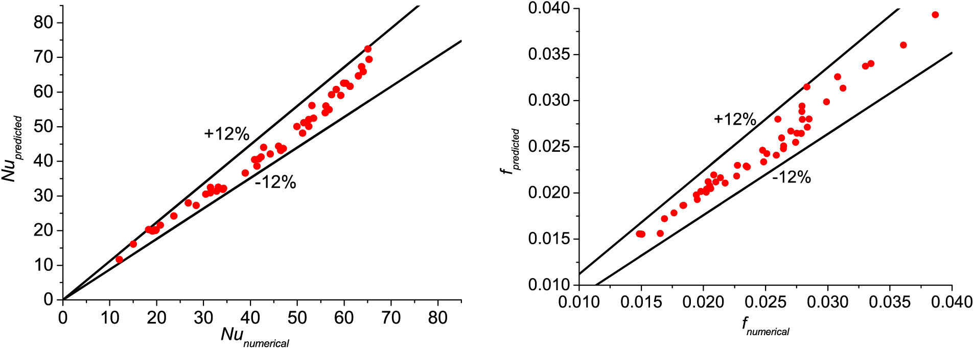
Figure 17: Plot of predicted data vs. numerical data of Nu and f
The cost of the collectors used in the experiment is approximately 800 yuan per unit. If the molds are used for mass production, the cost will definitely be reduced. The application of solar air collectors in engineering can save energy, reduce carbon emissions, and have other advantages, which are relatively economical and applicable.
The performance of hemispherical protrusion solar collectors is analyzed and studied from two aspects optics and thermodynamics. Through the comparative analysis of the light path and fluid flow of protrusion and dimples, it is concluded that the absorption rate of the hemispherical dimple is 10.3 percentage points higher than that of the protrusion. When the fluid flows through the protrusion, the heat transfer between the fluid and the protrusion can be enhanced, while the fluid flows through the dimple, the fluid forms a dead zone at the bottom of the dimple, resulting in the increase in local temperature and the decrease of heat exchange efficiency. Based on the analysis of its light path and flow, it can be concluded that the side facing the sun is the hemispherical dimples, which can maximize the absorption of solar radiation, while the side in contact with air is hemispherical protrusions, which can destroy the boundary layer of air flow and enhance heat transfer.
The effects of the relative height and spacing of hemispherical protrusion on the enhanced heat transfer and resistance characteristics are studied, and the correlations are obtained by nonlinear regression.
Acknowledgement: None.
Funding Statement: This work was supported by the Key Scientific Research Projects of Colleges and Universities in Henan Province (22B480007).
Author Contributions: The authors confirm contribution to the paper as follows: study conception and design: Xinli Wei; draft manuscript preparation and interpretation of results and partial data collection analysis: Shuilian Li; partial data collection analysis: Fan Zeng. All authors reviewed the results and approved the final version of the manuscript.
Availability of Data and Materials: The authors confirm that the data supporting the findings of this study are available within the article.
Conflicts of Interest: The authors declare that they have no conflicts of interest to report regarding the present study.
References
1. Zhang, H. F. (2007). Solar thermal utilization principle and computer simulation, 2ndXi’an, China: Northwest University of Technology Press. [Google Scholar]
2. Jia, Y. T., Alva, G., Fang, G. Y. (2019). Development and applications of photovoltaic-thermal systems: A review. Renewable and Sustainable Energy Reviews, 102, 249–265. https://doi.org/10.1016/j.rser.2018.12.030 [Google Scholar] [CrossRef]
3. Ronald, S., Katherine, F. (2003). Heat transfer and friction factors for flows inside circular tubes with concavity surfaces. Journal of Turbomachinery, 125, 665–672. https://doi.org/10.1115/1.1622713 [Google Scholar] [CrossRef]
4. Zheng, J. Y., Zhang, L., Liu, C. G. (2022). A numerical study on heat transfer enhancement and fluid flow of enhanced tube with ellipsoidal dimples and protrusions. Journal of Thermal Science and Engineering Applications, 14(9), 091007. https://doi.org/10.1115/1.4053739 [Google Scholar] [CrossRef]
5. Brij, B., Ranjit, S. (2010). A review on methodology of artificial roughness used in duct of solar air heaters. Energy, 35, 202–212. https://doi.org/10.1016/j.energy.2009.09.010 [Google Scholar] [CrossRef]
6. Sang, D. H., Hyun, G. K., Hyung, H. C. (2008). Heat transfer with dimple/protrusion arrays in a rectangular duct with a low Reynolds number range. International Journal of Heat and Fluid Flow, 29, 916–926. https://doi.org/10.1016/j.ijheatfluidflow.2008.01.004 [Google Scholar] [CrossRef]
7. Wu, H. J., Shan, S. Q., Zhou, Z. J. (2023). Performance analysis of a novel solar radiation cascade conversion system for combined heat and power generation based on spectrum splitting and reshaping. Journal of Renewable and Sustainable Energy, 15(3), 48–54. [Google Scholar]
8. Yu, C., Chew, Y. T., Khoo, B. C. (2013). Heat transfer and flow structure in turbulent channel flow over protrusions. International Journal of Heat and Mass Transfer, 66, 177–191. https://doi.org/10.1016/j.ijheatmasstransfer.2013.07.014 [Google Scholar] [CrossRef]
9. Jiang, F. Z. (2010). Study on the performance of honeycomb plate heat transfer element (Ph.D. Thesis). Zhengzhou University, Zhengzhou, China (In Chinese). [Google Scholar]
10. Liu, X. P., Zhang, S. J., Li, J. X. (2014). Heat transfer characteristics of approximate semi ellipsoidal corrugated plate heat exchanger. Journal of Nanjing University of Technology (Natural Science Edition), 36(3), 119–122. [Google Scholar]
11. Zhang, D., Guo, S., Xie, Y. H. (2014). Experimental study on heat transfer enhancement of cooling channel based on ball and socket. Applied Mathematics and Mechanics, 35, 254–263. [Google Scholar]
12. Saini, R. P., Jitendra, V. (2008). Heat transfer and friction factor correlations for a duct having dimple-shape artificial roughness for solar air heaters. Energy, 33, 1277– 1287. https://doi.org/10.1016/j.energy.2008.02.017 [Google Scholar] [CrossRef]
13. Kishor, D., Suhas, K., Pradeep, P. (2023). Experimental investigation of convective heat transfer performance of TiN nanofluid charged U-pipe evacuated tube solar thermal collector. Applied Thermal Engineering, 225, 152–158. [Google Scholar]
14. Brij, B., Ranjit, S. (2011). Nusselt number and friction factor correlations for solar air heater duct having artificially roughened absorber plate. Solar Energy, 85, 1109–1118. https://doi.org/10.1016/j.solener.2011.03.007 [Google Scholar] [CrossRef]
15. Yadav, S., Varun, S., Kaushal, M. (2012). Heat transfer and frictional characteristics of rectangular channel air heater duct having protrusion as roughness elements. Original Contribution, 93(4), 307–312. [Google Scholar]
16. Zeynep, A. Y. (2023). Numerical and experimental analyses of flow and hearer transfei characteristics in a chevrorn-tpe corrugated plate heat exchanger with graphene nanofluid. Heat Transfer Research, 54(1), 1–18. https://doi.org/10.1615/HeatTransRes.v54.i1 [Google Scholar] [CrossRef]
17. Muneesh, S., Varun, N. S. (2012). Correlations for solar air heater duct with dimpled shape roughness elements on absorber plate. Solar Energy, 86, 2852–2861. https://doi.org/10.1016/j.solener.2012.06.024 [Google Scholar] [CrossRef]
18. Kumar, R., Sharma, A., Goel, V. (2023). An experimental investigation of new roughness patterns (dimples with alternative protrusions) for the performance enhancement of solar air heater. Renewable Energy, 211, 964–974. https://doi.org/10.1016/j.renene.2023.04.111 [Google Scholar] [CrossRef]
19. Aman, S., Ranjit, S., Brij, B. (2017). Review on dimpled and protruded roughness geometries used in the duct of solar air heaters. International Journal of Advance in Science and Engineering, 6, 679–686. [Google Scholar]
20. Navneet, A., Varun, G., Bengt, S. (2023). Solar air heater performance enhancement with differently shaped miniature combined with dimple shaped roughness: CFD and experimental analysis. Solar Energy, 250, 33–50. https://doi.org/10.1016/j.solener.2022.12.024 [Google Scholar] [CrossRef]
21. Zhu, T. T., Diao, Y. H., Zhao, Y. H., Cheng, M. (2017). Performance evaluation of a novel flat-plate solar air collector with micro-heat pipe arrays (MHPA). Applied Thermal Engineering, 118, 1–16. https://doi.org/10.1016/j.applthermaleng.2017.02.076 [Google Scholar] [CrossRef]
22. Seyfi, S., Mesut, A. (2019). Thermal performance of flexible air duct using a new absorber construction in a solar air collector. Applied Thermal Engineering, 146, 123–134. https://doi.org/10.1016/j.applthermaleng.2018.09.100 [Google Scholar] [CrossRef]
23. Subhash, C., Prabha, C., Harish, K. G. (2022). Thermal performance enhancement of solar air heater using louvered fins collector. Solar Energy, 239, 10–24. https://doi.org/10.1016/j.solener.2022.04.046 [Google Scholar] [CrossRef]
24. Li, S. L., Wang, H. X. (2014). Studying the effects on the absorption rate of absorber plate having different surface shapes. Applied Mechanics and Materials, 641, 1010–1015. [Google Scholar]
25. Ben, S. R. (2007). The air solar collectors: Comparative study, introduction of baffles to favor the heat transfer. Solar Energy, 81, 139–149. https://doi.org/10.1016/j.solener.2006.05.002 [Google Scholar] [CrossRef]
26. Vishavjeet, S. H., Saini, R. P., Saini, J. S. (2011). Performance of artificially roughened solar air heaters—A review. Renewable and Sustainable Energy Reviews, 13, 1854–1869. [Google Scholar]
27. Smith, E., Pongjet, P. (2011). Influence of double-sided delta-wing tape insert with alternate-axes on flow and heat transfer characteristics in a heat exchanger tube. Chinese Journal of Chemical Engineering, 19, 410–423. https://doi.org/10.1016/S1004-9541(11)60001-3 [Google Scholar] [CrossRef]
28. Li, S. L., Meng, X. R., Wei, X. L. (2014). Numerical study of light reflection absorption affected by sinusoidal-corrugated solar air collector. Applied Solar Energy, 50(2), 90–97. https://doi.org/10.3103/S0003701X14020121 [Google Scholar] [CrossRef]
29. Li, S. L., Ma, X. L., Wei, X. L. (2014). Numerical simulation on thermal performance of the sinusoidal-corrugated solar air collector. Journal of Zhengzhou University, 35(3), 35–38 (In Chinese). [Google Scholar]
Cite This Article
 Copyright © 2024 The Author(s). Published by Tech Science Press.
This work is licensed under a Creative Commons Attribution 4.0 International License , which permits unrestricted use, distribution, and reproduction in any medium, provided the original work is properly cited.
 Downloads
 Citation Tools