 Open Access
ARTICLE
Numerical Investigation of Snow Prevention in the Bogie Region of High-Speed Trains with Active Blowing under Crosswind Conditions
1 State Key Laboratory of Rail Transit Vehicle System, Southwest Jiaotong University, Chengdu, 610031, China
2 College of Railway Transportation, Hunan University of Technology, Zhuzhou, 412000, China
3 GD Midea Air-Conditioning Equipment Co., Ltd., Foshan, 528000, China
* Corresponding Author: Jiye Zhang. Email:
(This article belongs to the Special Issue: Computational Fluid Dynamics: Two- and Three-dimensional fluid flow analysis over a body using commercial software)
Fluid Dynamics & Materials Processing 2024, 20(12), 2789-2808. https://doi.org/10.32604/fdmp.2024.055418
Received 26 June 2024; Accepted 15 August 2024; Issue published 23 December 2024
Abstract
In this study, the unsteady Reynolds-averaged Navier–Stokes algorithm coupled with the Discrete Phase Model (DPM) was used to study the accumulation of snow in the bogie region of a high-speed train under crosswind conditions. Moreover, the impact of active blowing schemes on the airflow around the bogie and the dynamics and deposition of snow particles were also assessed. According to the results: in the crosswind environment, active blowing changes the flow field in the bogie area, reducing the flow of air coming from the windward side and bottom of the bogie. The trajectory of snow particles carried by crosswinds is modified due to the reduced airflow into the bogie region. With no active blowing, snow accumulation is mainly concentrated in the bogie cavity, frame, and primary suspension; while it is reduced by nearly an order of magnitude as soon as blowing is enabled. Blowing speeds need to be distributed appropriately in order to achieve the best possible snow protection. Continuously increasing the blowing speed on one side does not improve the amount of snow in the bogie region. The optimal condition for snow prevention of the entire train is achieved with a windward side blowing speed of 4 m/s and a leeward side blowing speed of 6 m/s, resulting in a snow reduction rate of 95.6%. Moreover, higher blowing speeds on the leeward side are beneficial for mitigating snow accumulation in the bogie region.Keywords
Nomenclature
| | Air flow velocity (m/s) |
| | Particle velocity (m/s) |
| | Reynolds number |
| | Aerodynamic viscosity (Pa∙s) |
| | Resistance coefficient of particle |
| | Gravitational acceleration (m/s2) |
| | Fluid density (g/cm3) |
| | Particle density (g/cm3) |
| | Diameter of the particles (m) |
| | Particle mass (kg) |
| | The Hamiltonian operator |
| | The stress tensor |
| | The volume force (N) |
| | The Kronecker symbol |
| | The angular deformation rate of the fluid microcluster |
With the development of high-speed railways, it is crucial for high-speed trains to possess excellent environmental adaptability and maintenance capabilities. Nevertheless, in areas with cold temperatures and high snow content, a challenge arises with the buildup of snow and ice in the bogie region. The snow in the bogie cavity will melt when heated, and then sticks to components with lower temperatures, resulting in the creation of ice [1,2]. This phenomenon is illustrated in Fig. 1a. When the ice accumulation on the bogie reaches a specific threshold, it has the potential to solidify the suspension and braking system, creating a hazardous situation for passengers. In order to tackle this problem, numerous countries have implemented localized measures for prevention and control. For instance, BM71 trains in Norway have incorporated snow shields systems to mitigate the impact of ice and ballast, as depicted in Fig. 1b. Similarly, the SM3 trains in Finland is equipped with a retractable shield on the secondary suspension to prevent freezing, as shown in Fig. 1c. However, the approaches are hindered by challenges such as the complexity of inspection, suboptimal efficiency, cumbersome maintenance, and the arduous task of removing snow and ice.

Figure 1: The amount of snow in the bogie area and methods for preventing snow: (a) bogie, (b) primary suspension shield, (c) secondary suspension shield
With the development of computational fluid dynamics, its accuracy as well as reliability has been gradually improved, numerical simulation is becoming an effective tool for studying train aerodynamics [3,4], In addition, some scholars began to use numerical simulation to study the simple three-dimensional structure or building snow accumulation problem (Serine et al. [5], Thiis et al. [6] and Beyers et al. [7]), and then Allain et al. [8] investigated the mechanism of snow accumulation at the bottom of high-speed trains by means of experiments and numerical simulations, and then people began to use flow control methods to mitigate snow attachment in the bogie region of high-speed trains. Gao et al. [9,10] confirmed through wind tunnel tests that numerical simulation can accurately predict the snow accumulation in the bogie region, and suggested that installing deflectors may reduce the snow accumulation on the bogie surface. Wang et al. [11] recommended covering the brake caliper with snow shields to maintaining optimal braking performance and preventing ice buildup. However, Cai et al. [12] found that front deflector installation can exacerbate snow accumulation around the back plate and bottom of the rear cabin.
Several flow control approaches have been evaluated for their effectiveness in avoiding snow buildup. Liu et al. [13] highlighted methods such as the rectifier arrangement of bogies and the shape of deflectors. Zhang et al. [14] and Wang et al. [15] confirmed that deflectors and wheelset snow shields reduce snow and ice buildup in icing wind tunnel investigations. Gao et al. [10] noted that passive flow control increases air resistance due to the larger surface area exposed to the wind. Conversely, active blowing has been shown by numerous researchers to significantly decrease aerodynamic resistance in high-speed trains. Xiong et al. [16] explored injecting helium to reduce drag of top and side of the train, finding that an optimal strategy could lower train resistance by 10.93%. Similarly, Huang et al. [17] employed numerical modeling to study the effects of jet streams on drag reduction, while Chen et al. [18] reported that trains with air jets exhibit better aerodynamics and less airflow impact in crosswind environment.
There is limited literature on active snow protection for bogie areas. Azuma et al. [19] proposed utilizing heat from air conditioners in snow-melting systems. Lan et al. [20] found that in the absence of crosswind, active blowing effectively prevents snow buildup in the bogie region. However, the complexity of high-speed train operating conditions, especially crosswind conditions during heavy snowfall, has not been fully studied. Niu et al. [21] and Li et al. [22] demonstrated complicated flow dynamics in crosswind conditions, showing that snow particles are easy to migrate into the bogie area. Guo et al. [23,24] and Gao et al. [25] proved that the structure of the bogie area greatly affects the flow field. According to Paulukuhn et al.’s study [26], the airflow from the roof of the bogie region is diverted to the bogie equipment compartment for ventilation and heat dissipation by setting up ducts, based on the above, this paper applies the flow control method of active blowing to the bogie region under crosswind environment to investigate the flow field characteristics and the effect of anti-accumulation of snow in the bogie region under crosswind environment.
The main purpose of this study is to investigate the effect of the arrangement of active air blowing in the bogie area under crosswind conditions on the snow accumulation and flow field of high-speed trains, as shown in Fig. 2. Two types of blowing port methods are introduced: One is to divide the bogie area into the windward blowing port and the leeward blowing port, and the other is to distinguish the front blowing port and the rear blowing port. In fluent, the boundary conditions of each blowing port are set as the velocity inlet, the blowing area of each blowing port is the same, and the total flow rate per unit area of each bogie blowing port is 5 m3/s. By reasonably arranging the blowing velocities in different areas of the same bogie, the effect of active blowing on preventing snow accumulation is studied. Table 1 lists the air-blowing configurations for all scenarios, notably F5R5 and W5L5 represent the same setting. W4L6 represents a blowing speed of 4 m/s on the windward side and 6 m/s on the leeward side; F4R6 represents a blowing speed of 6 m/s on the front side and 4 m/s on the rear side.

Figure 2: Different blowing port arrangements

The train model employed in this study comprised a full-size 1/2 middle car and a full-size head car. Due to computational resource constraints, the model was simplified by omitting certain components, including the train’s air conditioning system, pantograph, windshield, undercarriage equipment, and bogie, as depicted in Fig. 3. The head car was equipped with trailer bogies, whereas the middle car equipped motor bogie.

Figure 3: Geometric model: (a) train, (b) bogie
2.2 Computational Domain and Grid
The car body height is represented by the feature height H, and the computational domain is 60 H in length, 24 H in width, and 16 H in height, as shown in Fig. 4. The train’s head is 11 H distant from the ABCD surface, and the train’s tail is 40 H distant from the EFGH surface. Three refinements box surrounding the bogies and train, as shown in Fig. 5, to solve the flow characteristics of bogie regions more precise, the refinement region 1 is encrypted for each bogie region. The bogie and car-body have eight prismatic layers, the first of which is 0.001 m high with the growth rate is 1.25, and the mesh number is 34 million.
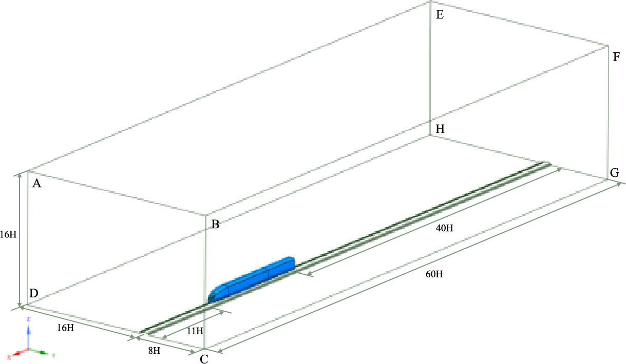
Figure 4: Computational domains

Figure 5: Body mesh with boundary layer
2.3 Boundary Conditions and Calculation Settings
In accordance with the findings of Zha et al. [27], the probability of average wind speed exceeding 10 m/s is relatively low in many areas, so the crosswind speed of 10 m/s was selected for this study. In order to simulate the train operating environment with a train speed of 250 km/h and 10 m/s crosswinds, the ABCD and BFGC surfaces were set as the velocity inlet, whose X-direction velocity component is Ux = 70 m/s, and Y-direction velocity component is Uy = 10 m/s, and the yaw angle
where
For a Newtonian fluid:
where

Figure 6: Position of the snow particle injection plane in numerical simulations

After the steady state calculation results converged, the DPM was run to simulate extremely heavy Snowstorm conditions by injecting about 6000 snow particles at each time step with velocity direction aligned with the velocity inlet surface. In this paper, light dry snow (with low water content), which is more likely to form wind and snow streams, is used as a research target, the diameter of snow particles is 0.2 mm, with a density of 150 kg/m3 [30–32]. Total solution simulation duration is 2 s, and the time step is 0.0005 s. The force balance equation of snow particles is as follows [33]:
where
where μ is aerodynamic fluid viscosity,
2.4 Grid Independence Verification
Three sets of sparsely spaced grids were generated, namely coarse grid, medium grid, and fine grid. Each set of grids consisted of eight prismatic layers, with the first prismatic layer measuring 1 mm in thickness, Table 3 displayed the characteristics for the various grid sizes, using the same boundary conditions as the wind tunnel tests (Xia et al. [34]), the original model was numerically simulated for grid-independence validation. Fig. 7a shows a comparison among the pressure coefficients of the top centerline of three sets of grids and wind tunnel test data, the pressure coefficients (Cp) from the numerical simulations and wind tunnel tests show a high degree of agreement, emphasizing the accuracy and reliability of the simulation methodology used. Fig. 7b,c shows the pressure coefficients (Cp) and velocity (
where

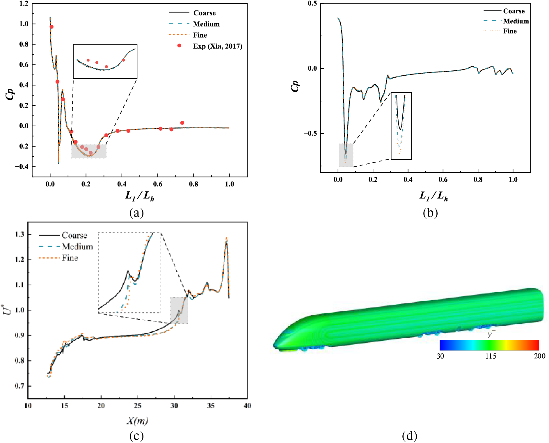
Figure 7: Mesh sensitivity analysis: (a) Change in pressure coefficient at the centerline of the roof surface of the head car [34]; (b) Change in pressure coefficient at 0.2 m from the bottom of the head car; (L1: distance to the head of the train, Lh: overall length of the head car); (c) Dimensionless velocity change; (d) Wall y+
Due to the lack of experimental equipment for this work, it is not possible to verify the correctness of the DPM model by comparing numerical simulation results with experimental data. However, researchers at Central South University have successfully reproduced the wind tunnel results using the DPM mode by Wang et al. [35–37].
3.1 Fluid Characteristics in the Bogie Region
To study the effect of active blowing on the flow field in the bogie area under crosswind conditions, three parallel vertical sampling planes were set up at different heights along the Z-axis, and three spreading sampling planes were established along the Y-axis in the bogie region. The specific locations are illustrated in Fig. 8.

Figure 8: Relative positions of the cross-sections: (a) body-related Z-plane, (b) bogie Y-plane
Fig. 9 shows the streamline distribution of Plane 1 in bogie region 1. In the original model, the airflow below the bogie separates and reaches the top of the bogie as the wheels rotate, and then merges with the airflow separated from the front and rear wheels. Active airflow subsequently alters this phenomenon, preventing the airflow beneath the bogie from ascending into the cavity, where increasing the velocity of the airflow at the front or on the windward side both simplify the flow field structure and reduce vortex formation.

Figure 9: Streamline distribution of the Plane 1 in bogie region 1
Fig. 10 compares the streamline distributions of Planes 2 and 3 in the bogie region, at the altitude of Plane 2, high-speed airflow enters the bogie region directly from the windward side (near the primary suspension, secondary suspension, anti-snake damper, and air springs). This complexity within the bogie region significantly influences airflow disturbances, leading to the formation of small vortex structures, especially in corners. The flow speed gradually decreases before exiting from the rear of the leeward side. By changing the airflow speed on the windward and leeward sides of the bogie, it can be observed that an effect similar to an air curtain appears on the windward side. The air curtain prevents high-speed airflow from directly impacting the bogie, reduces the speed of airflow, promotes airflow to be discharged from the bogie region, and minimizes the formation of small vortex structures in the cavity. Meanwhile, increasing the airflow velocity on the windward side enhances the effectiveness of the air curtain. Changing the airflow speed at the front and rear parts of the bogie also reduces the direct influx of airflow from the windward side into the bogie region. In the higher section of Plane 3, protected by the skirt, airflow can only enter the bogie region from lower positions of the skirt. This results in higher flow velocities in the mid and rear sections of the bogie, while the front experiences lower velocities, leading to two larger vortex structures in the front cavity of the original model. In contrast, the air curtain effect brought by active airflow reduces the influence of crosswinds on vortex structures, simplifies the streamline of the bogie region, and helps air to be more easily discharged.
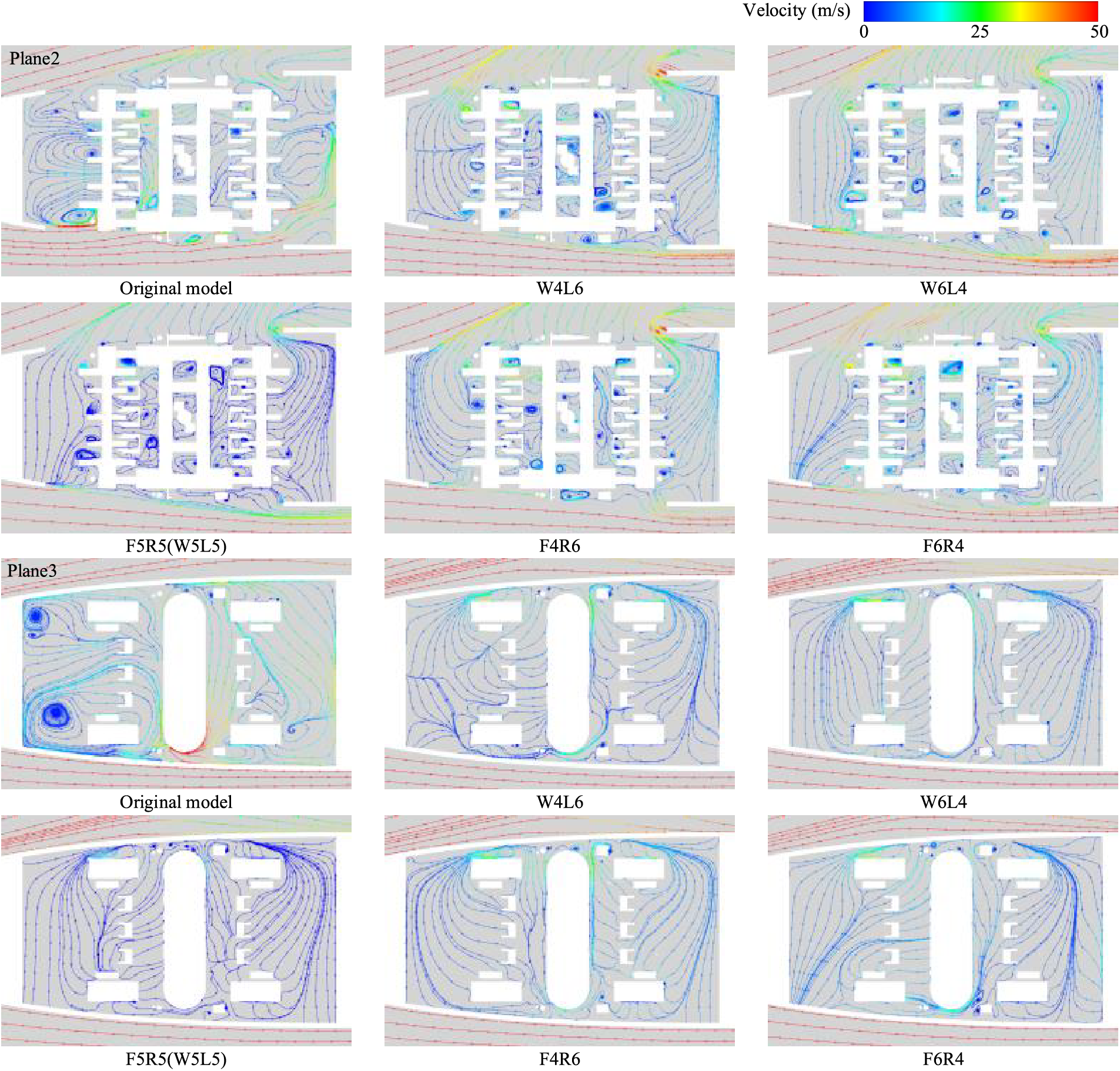
Figure 10: The streamline distributions of Planes 2 and 3 in the bogie region 1
Fig. 11 illustrates the pressure variations in Plane 4. Following active air intervention, the significant increase in pressure near the bottom of the bogie shown in the dashed box after active air intervention reduces the pressure difference between the inside and outside of the bogie. This makes it more difficult for airflow to rise from the bottom of the bogie to the bogie area, thus reducing the likelihood of snow particles entering the bogie region.
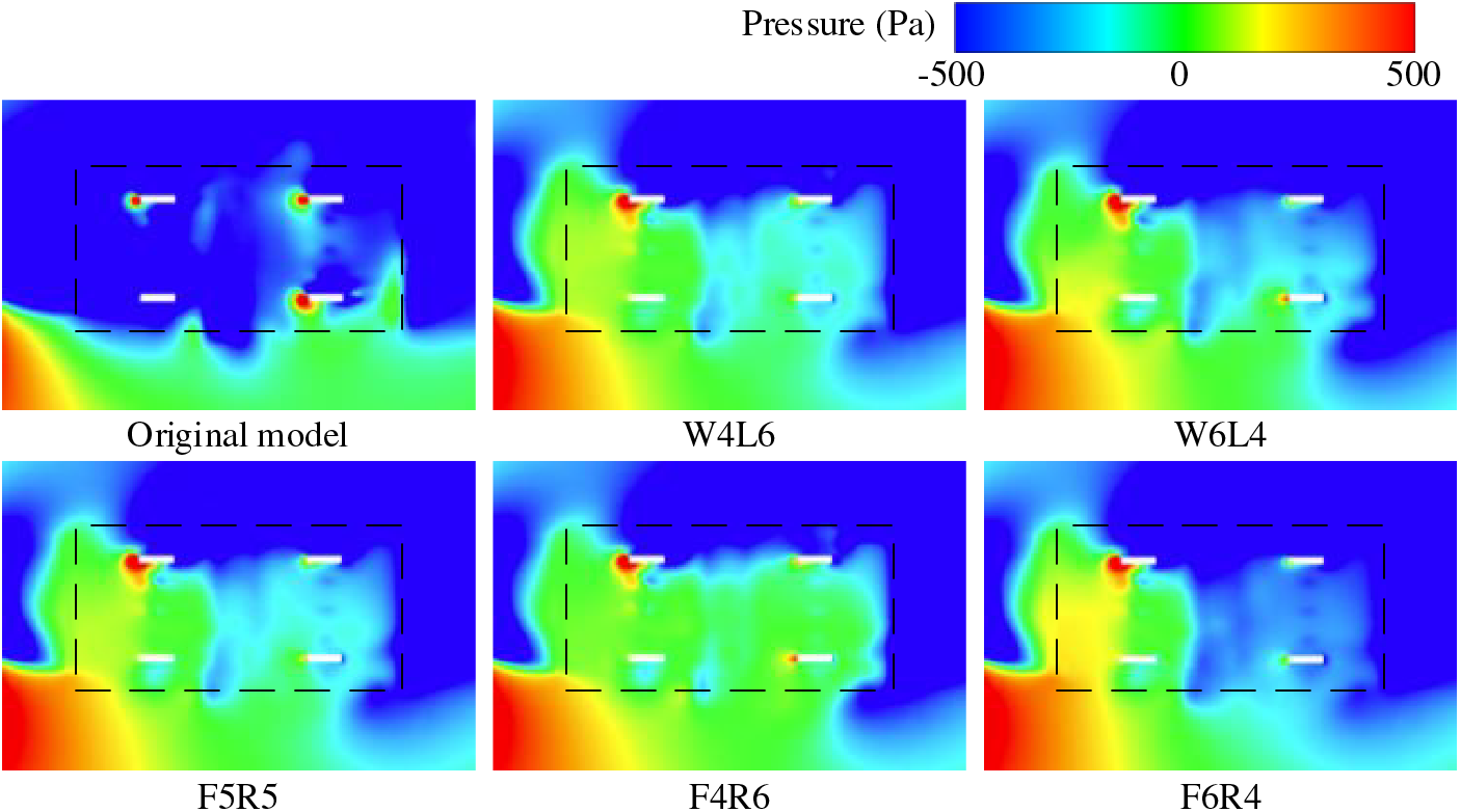
Figure 11: Pressure distribution in the Plane 4 at the bottom of the bogie
Figs. 12 and 13 illustrate the pressure distribution in the front and bottom regions of the bogie, respectively. After active airflow intervention, the pressure on the windward side of the bogie increases. Comparing the case W4L6 and case W6L4, it is evident that increasing the airflow speed on the leeward side while decreasing it on the windward side results in a more uniform pressure distribution on the bogie surface, with minimal differences between the leeward and windward sides. In contrast, comparison case F4R6 and case F6R4, show that a higher airflow speed at the front compared to the rear leads to a significant pressure difference between the front and rear of the bogie. In addition, active blowing reduces the aerodynamic forces of crosswinds directly affecting the surface of the cavity, thereby reducing the pressure on the rear plate, as shown in the area within the elliptical box in Fig. 13.
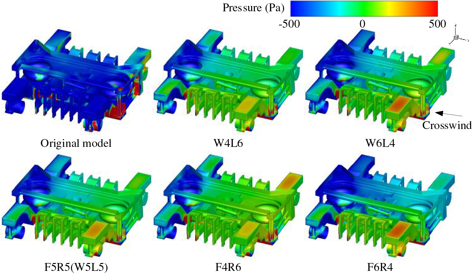
Figure 12: Pressure distribution on the top surface of the bogie 1
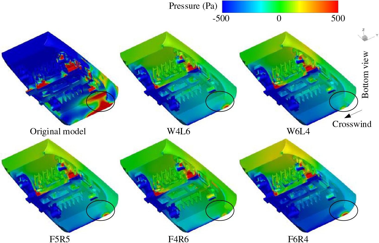
Figure 13: Pressure distribution on the bottom surface of the Bogie 1
3.2 Snow Particles Distribution in a Crosswind Condition
In bogie region 1, Fig. 14 illustrates the snow concentration distribution across three distinct planes: Plane 5 near the leeward side, Plane 1 in the middle, and Plane 6 near the windward side. Overall, the snow particle concentration on the Plane 5 is higher than that on the Plane 4. In the original model, snow particles permeate the entire bogie area. However, following active airflow intervention, the height of snow particles rising significantly decreased. Reducing the airflow speed on the leeward side leads to an increase in the range of snow particle activity, while reducing the airflow speed at the rear results in an increase in the height and concentration of snow particles.
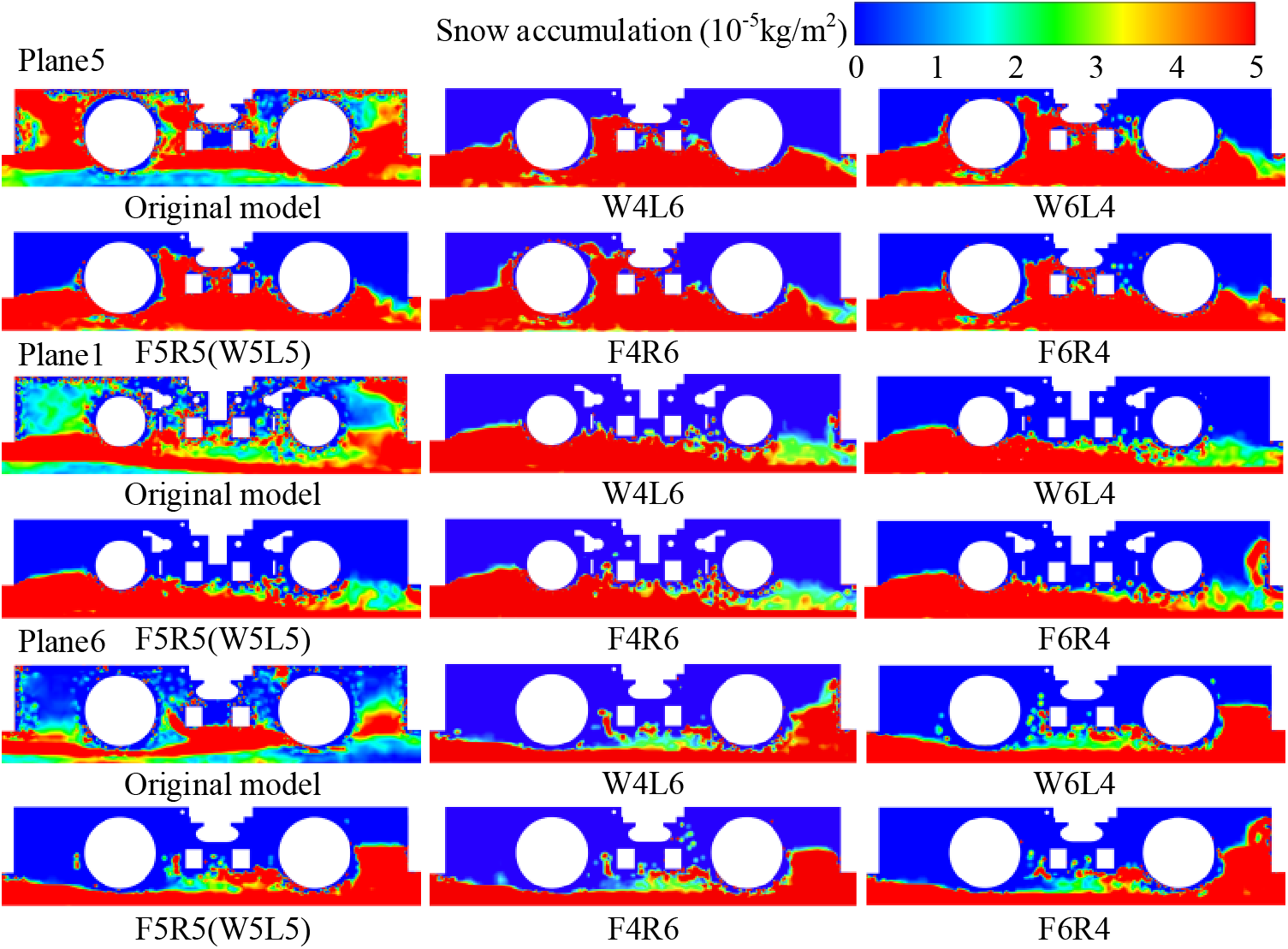
Figure 14: Distribution of snow particle concentrations in one end bogie Plane 1, Plane 5, and Plane 6
To investigate the process of snow particles entering the bogie region under crosswind conditions and their lateral distribution in the bogie region, Fig. 15 shows the three-dimensional flow paths of the airflow outside the bogie into and out of the bogie region, while Fig. 16 shows the distribution of snow particle concentrations on Plane 3 within the regions of Bogies 1 and 2. The arrows in Figs. 15 and 16 indicate the trajectories of the snow particles and airflow as they enter the bogie region. In the original model, airflow carrying snow particles mainly entered the bogie area from the primary suspension, secondary suspension, transverse damper, areas near the rear panel of the bogie cabin (as indicated by arrows in Fig. 15), and the bottom of the structure on the leeward side (dashed box in Fig. 15). With active blowing, the airflow into the bogie area from the windward side and the bottom of the bogie is significantly reduced, Increasing the blowing speed on the leeward side of the bogie and the front blowing speed helps to reduce the airflow from the bottom into the bogie region, thus reducing the concentration of snow particles. The situation for Bogie 2 is similar to that of Bogie 1.
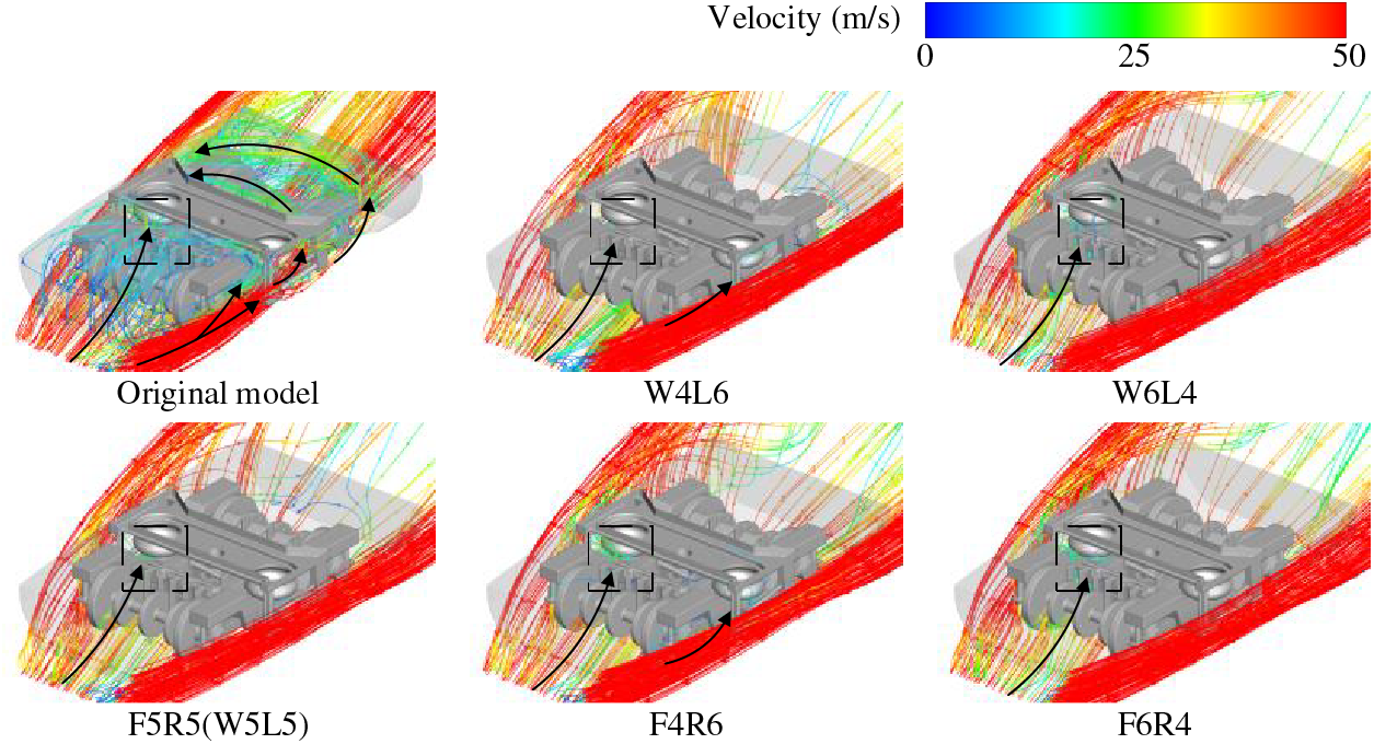
Figure 15: Path of airflow from outside the bogie into and out of the bogie region
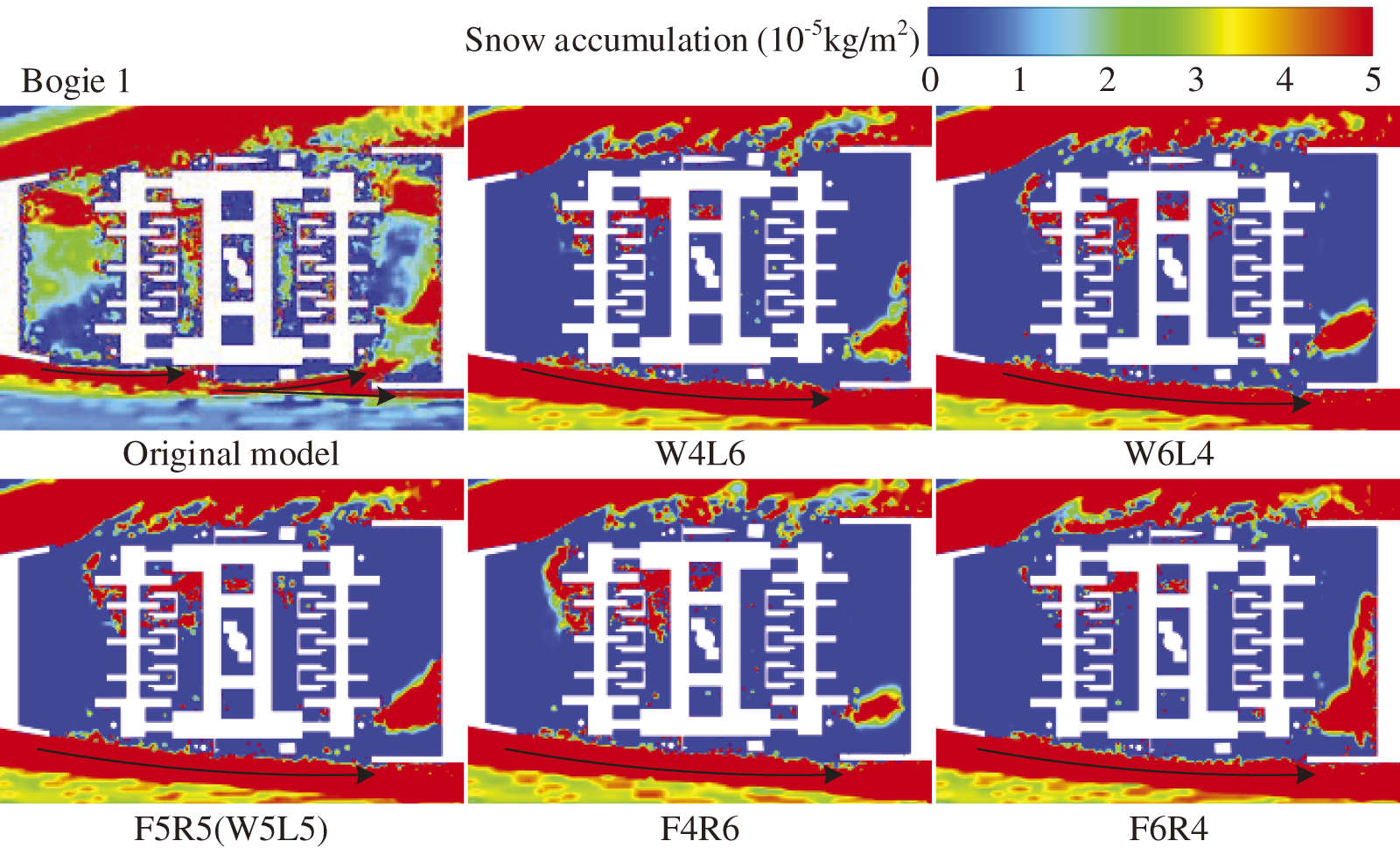
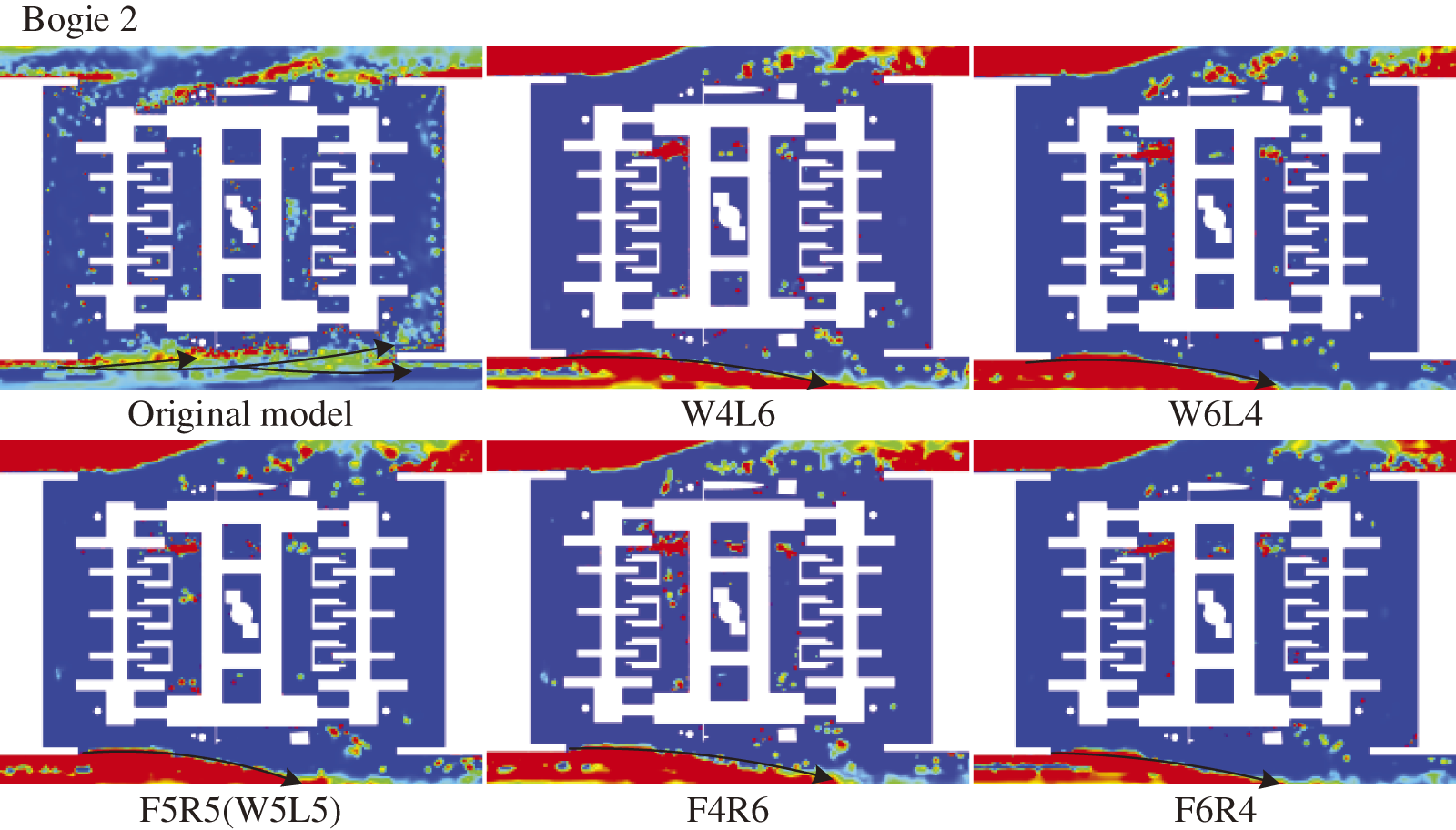
Figure 16: Distribution of snow concentrations in Plane 3
3.3 Snow Particles Depositional Characteristics in Crosswind Conditions
Fig. 17 illustrates the snow accumulation distribution on the bogie surface. Based on the airflow paths entering the bogie shown in Fig. 15, The areas directly affected by crosswinds, such as the windward side of the transverse damper and the leeward side of the bogie bottom, have more severe snow accumulation. After active air blowing, there are significant changes in the snow distribution on the bogie surface, particularly on the windward side, including the bolster, brake caliper, air springs, the bottom and windward face of the structure (as indicated by the circular and dashed boxes in Fig. 17). As the blowing speed on the windward side increases and the speed on the leeward side decreases, the difference in snow accumulation near the leeward side of the bogie becomes more pronounced. Additionally, as the front blowing speed increases and the rear speed decreases, the changes in snow accumulation on the upper part of the bogie and the bottom of the leeward side of the structure become more evident (as shown in the dashed box in Fig. 17).

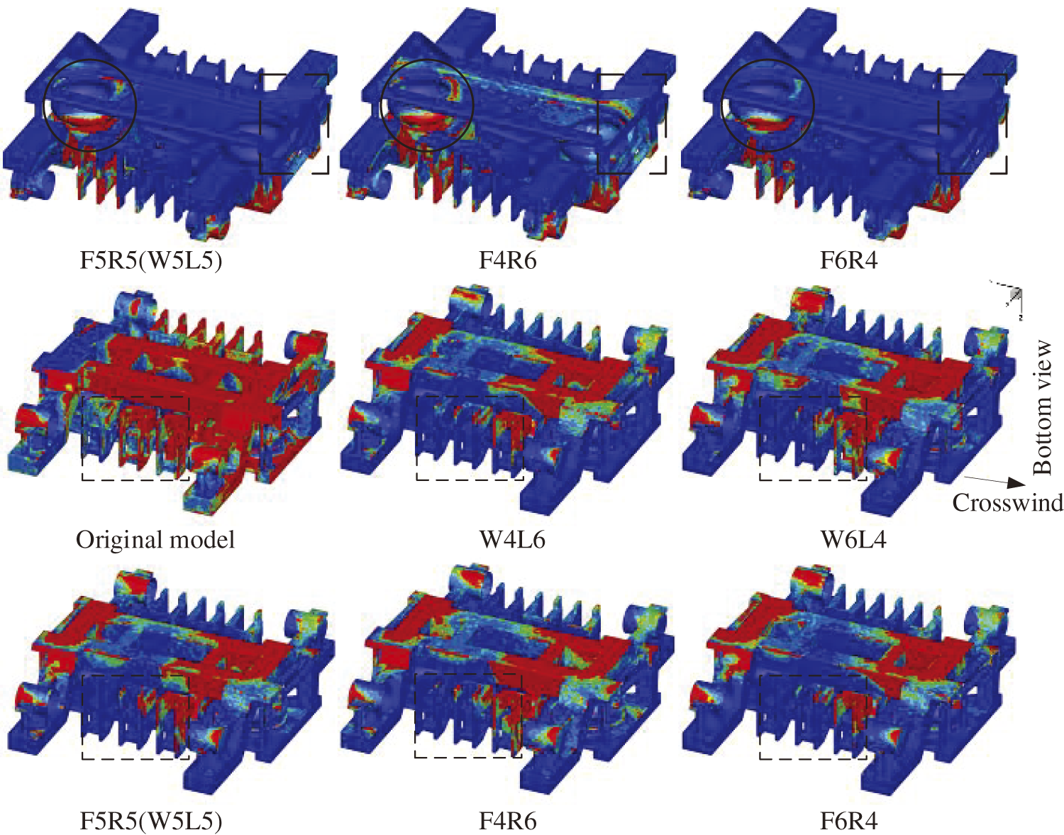
Figure 17: Snow distribution on the surfaces of the Bogie 1
The above analysis is based on a qualitative analysis, which can only result in an approximate snow mass distribution. Table 4 gives the snow accumulation of the main components in the region of Bogie 1. Fig. 18a,b shows the total snow accumulation mass on the bogie surface in different cases and the reduction rate of snow accumulation compared to the original model. It can be seen that, for a certain air supply, the snow mass on the bogie surface increases gradually with the increase of the air blowing speed on the windward side (and the corresponding decrease of the air blowing speed on the leeward side), and a larger air blowing speed on the leeward side is more favourable for snow control. With the increase of air blowing speed on the front side (and the corresponding decrease of air blowing speed on the back side), the snow accumulation shows a tendency of increasing and then decreasing, the asymmetric air blowing speed arrangement scheme has less snow accumulation. Comparing the two different blowing arrangements, the snow accumulation of W4L6 is significantly lower, and the symmetrical longitudinal arrangement of the blowing ports is better than the front and rear arrangement in terms of snow protection.

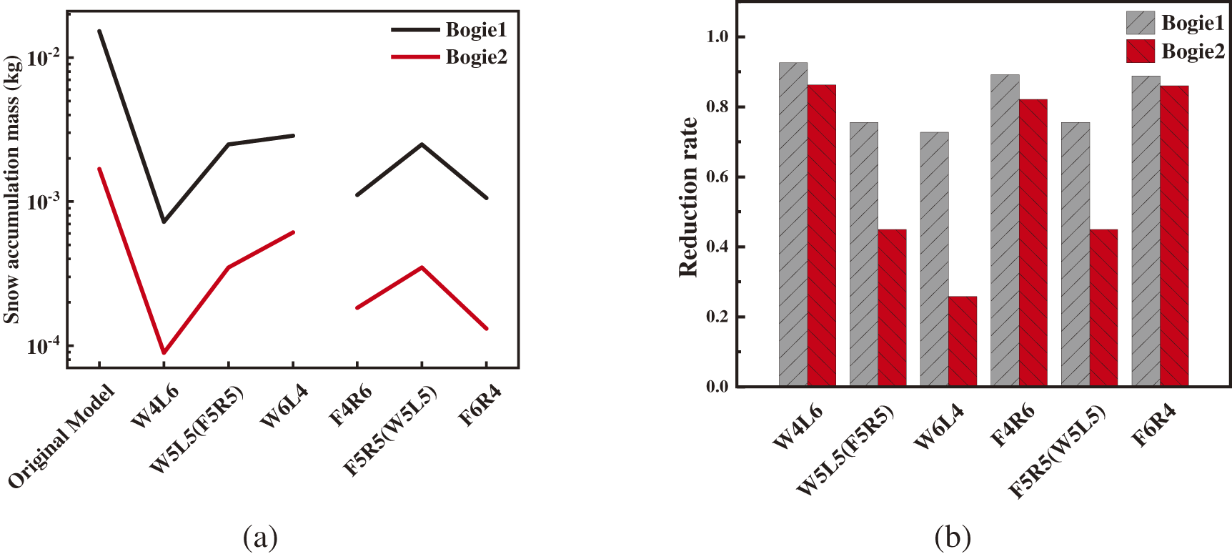
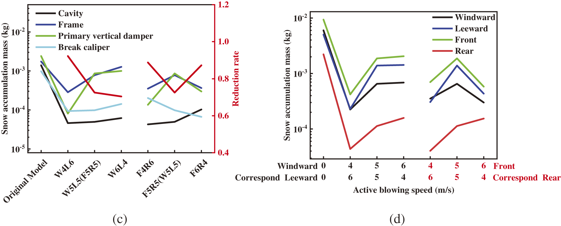
Figure 18: (a) Snow accumulation mass of the bogie (t = 2 s); (b) Reduction rate of snow accumulation; (c) Components with the most snow accumulation (t = 2 s); (d) Snow accumulation at different blowing speeds on the windward and leeward sides, and on the front and rear sides (t = 2 s)
Based on the snow accumulation mass in Table 4, Fig. 18c gives the snow accumulation and snow protection rate of the components with more snow accumulation in the Bogie 1 area, such as Cavity, Frame, Primary vertical damper, Break caliper, under different blowing schemes, their snow accumulation occupies 70% of the entire bogie snow accumulation, due to the fact that these components are subjected to a large number of wind and snow flow impacts, the snow accumulation is larger; in the active blowing scheme, the blowing slows down the direct impact of the high-speed airflow, the airflow velocity decays, and its ability to carry snow particles in motion is weakened, resulting in a decrease in snow accumulation. Fig. 18d compares the snow accumulation of some parts of the bogie located on the windward and leeward sides, the front side and the rear side under different blowing scenarios, including brake caliper, Axle box, Primary vertical damper, swivel arm. Under a certain air supply, the snow accumulation on the windward and leeward sides showed an upward trend with the increase of the blowing speed on the windward side, and the snow accumulation did not show a linear increase or decrease with the increase of the blowing speed on the front side.
The blowing speeds need to be reasonably distributed in order to achieve the best snow protection, and continuously increasing the blowing speed on one side did not improve the amount of snow in the bogie region. Among all the design schemes, Scheme W4L6 has the highest snow protection rate of the whole vehicle, which reaches 95.6%. In addition, comparing the front and rear arrangements of the blowing ports, the average snow protection rate is higher for the blowing port arrangements on the windward and leeward sides, and increasing the blowing speed on the leeward side is more effective in preventing snow accumulation in the bogie area under crosswind conditions compared to increasing the blowing speed on the windward side.
This study investigates the effects of different blowing schemes on the flow field characteristics in the bogie region and the snow accumulation on the bogie surface of a high-speed train in a crosswind environment, and the main conclusions are as follows:
(1) Active air blowing alters the pressure difference between the bogie compartment and the external environment. This reduces the airflow entering the bogie region from the windward side, making it more difficult for bottom airflow to rise into the bogie region, thus simplifying the flow field: the airflow velocity decreases, vortices within cavities are reduced, flow direction becomes clearer, facilitating easier exit from the bogie area.
(2) Snow accumulation is notably influenced by crosswinds. Areas such as the windward side of the anti-snake damper and the leeward side of the frame’s bottom see heavier snow accumulation. Active blowing effectively reduces snow particle rise and entry into the bogie region from the windward side and bottom. Increasing blowing speed on the leeward side and front of the bogie further diminishes airflow and snow particle concentration within the bogie region.
(3) Snow accumulation zones are primarily the bogie cavity, frame, primary vertical damper, and brake caliper, which are directly impacted by high-speed airflow. Active blowing decreases airflow velocity and reduces snow accumulation. Optimal air supply distribution among blowing ports, under rated air supply conditions, achieves a snow prevention rate exceeding 95%. Specifically, increasing the blowing speed on the leeward side proves most effective in preventing snow buildup on the bogie surface.
In summary, active blowing schemes are highly effective in reducing snow accumulation and optimizing the flow field around the bogie region of high-speed trains in crosswind conditions. By strategically increasing blowing speeds, particularly on the leeward side, snow prevention rates can exceed 95%, ensuring better operational efficiency and safety for high-speed trains in snowy environments.
Acknowledgement: The authors acknowledge the computing resources provided by the State Key Laboratory of Rail Transit Vehicle System, Southwest Jiaotong University, China.
Funding Statement: The authors disclosed receipt of the following financial support for the research, authorship and/or publication of this article: This work was funded by the National Natural Science Foundation of China (Grant No. 12172308), the Provincial Natural Science Foundation of Hunan (Grant No. 2023JJ40260).
Author Contributions: Yao Zhang: Writing—Original Draft, Data Curation, Visualization, Methodology. Hong Lan: Conceptualization, Writing—Review & Editing. Jiye Zhang: Writing—Review & Editing, Funding acquisition. Lu Cai: Software, Writing—Review & Editing. Yuzhe Ma: Validation Writing—Review & Editing. All authors reviewed the results and approved the final version of the manuscript.
Availability of Data and Materials: The datasets generated during and/or analyzed during the current study are available from the corresponding author on reasonable request.
Ethics Approval: Not applicable.
Conflicts of Interest: The authors declare no conflicts of interest to report regarding the present study.
References
1. Bettez M. Winter technologies for High Speed Rail (Theses). Norway: Norwegian University of Science and Technology; 2011. [Google Scholar]
2. Kloow L, Jenstav M. High-speed train operation in winter climate. Stockholm, Sweden: KTH Railway Group and Transrail; 2011. [Google Scholar]
3. Dai ZY, Li T, Krajnović S, Zhang WH. Kriging-based multi-objective optimization on high-speed train aerodynamics using sequential infill criterion with gradient information. Phys Fluids. 2024;36(3):35168. doi:10.1063/5.0198990. [Google Scholar] [CrossRef]
4. Li T, Dai ZY, Yu MG, Zhang WH. Numerical investigation on the aerodynamic resistances of double-unit trains with different gap lengths. Eng Appl Comput Fluid Mech. 2021;15(1):549–60. doi:10.1080/19942060.2021.1895321. [Google Scholar] [CrossRef]
5. Serine A, Shimura M, Maruoka A, Hirano H. The numerical simulation of snowdrift around a building. Int J Comput Fluid Dyn. 1999;12(3–4):249–55. doi:10.1080/10618569908940829. [Google Scholar] [CrossRef]
6. Thiis TK. Comparison of numerical simulations and full-scale measurements of snowdrifts around buildings. Wind Struct. 2000;3(2):73–82. doi:10.12989/was.2000.3.2.073. [Google Scholar] [CrossRef]
7. Beyers HM, Sundsbø PA, Harms TM. Numerical simulation of three-dimensional, transient snow drifting around a cube. J Wind Eng Ind Aerod. 2004;92(9):725–47. doi:10.1016/j.jweia.2004.03.011. [Google Scholar] [CrossRef]
8. Allain E, Paradot N, Ribourg M, Delpech P, Bouchet JP, De La Casa X, et al. Experimental and numerical study of snow accumulation on a high-speed train. In: 49th International Symposium of Applied Aerodynamics, 2014; Lille; p. 24–5. [Google Scholar]
9. Gao GJ, Zhang Y, Xie F, Zhang J, He K, Wang J, et al. Numerical study on the anti-snow performance of deflectors in the bogie region of a high-speed train using the discrete phase model. Proc IMechE, Part F: J Rail Rapid Transit. 2019;233(2):141–59. doi:10.1177/0954409718785290. [Google Scholar] [CrossRef]
10. Gao GJ, Chen Q, Zhang J, Zhang Y, Tian Z, Jiang C. Numerical study on the anti-snow performance of deflectors on a high-speed train bogie frame. J Appl Fluid Mech. 2020;13(5):1377–89. [Google Scholar]
11. Wang JB, Gao GJ, Zhang Y, He K, Zhang J. Anti-snow performance of snow shields designed for brake calipers of a high-speed train. Proc IMechE, Part F: J Rail Rapid Transit. 2019;233(2):121–40. doi:10.1177/0954409718783327. [Google Scholar] [CrossRef]
12. Cai L, Lou Z, Li T, Zhang J. Numerical study on the effects of anti-snow deflector on the wind-snow flow underneath a high-speed train. J Appl Fluid Mech. 2020;14(1):287–99. [Google Scholar]
13. Liu YS, Li G, Zhang J. Wind tunnel studies on the prevention of particle accumulation onto the bogie of high-speed train. J Front Earth Sci. 2022;10:829309. doi:10.3389/feart.2022.829309. [Google Scholar] [CrossRef]
14. Zhang Y, Wang J, Jiang C, Zhang J, Wang T, Gao G. Investigation of ice and snow accumulations on the bogie areas of high-speed trains using ice wind tunnel experiments. J Cold Regions Sci Technol. 2022;199:103560. doi:10.1016/j.coldregions.2022.103560. [Google Scholar] [CrossRef]
15. Wang TT, Wang Y, Gao GJ, Zhao C, Jiang C. Experimental investigations on the performance of anti-snow designs for urban rail train bogies. J Wind Eng Ind Aerodyn. 2022;221:104913. doi:10.1016/j.jweia.2022.104913. [Google Scholar] [CrossRef]
16. Xiong XH, Xie PH, Liang XF. Study on aerodynamic drag reduction of high speed train body by Helium injection. J Railway Sci Eng. 2023;20(2):432–40. [Google Scholar]
17. Huang S, Yu Y, Li Z, Che Z. Study of aerodynamic drag reduction of high-speed train based on tail jet-flow control. J China Railw Soc. 2021;43:38–46. [Google Scholar]
18. Chen ZW, Ni YQ, Wang YW, Wang SM, Liu TH. Mitigating crosswind effect on high-speed trains by active blowing method: a comparative study. J Eng Appl Comput Fluid Mech. 2022;16(1):1064–81. doi:10.1080/19942060.2022.2064921. [Google Scholar] [CrossRef]
19. Azuma T, Horikawa S, Fujino K. Countermeasure against snow. J Japan Railway East Tech Rev. 2010;16:31–4. [Google Scholar]
20. Lan H, Cai L, Zhang J, Xu G. Research on snow prevention in the bogie region based on active blowing method. Proc IMechE, Part C: J Mech Eng Sci. 2024;238(12):5597–609. doi:10.1177/09544062231207700. [Google Scholar] [CrossRef]
21. Niu JQ, Zhou D, Liang XF. Numerical simulation of the effects of obstacle deflectors on the aerodynamic performance of stationary high-speed trains at two yaw angles. Proc IMechE, Part F: J Rail Rapid Transit. 2018;232(3):913–27. doi:10.1177/0954409717701786. [Google Scholar] [CrossRef]
22. Li T, Dai ZY, Zhang WH. Effect of RANS model on the aerodynamic characteristics of a train in crosswind using DDES. Comput Model Eng Sci. 2020;122(2):555–70. doi:10.32604/cmes.2020.08101. [Google Scholar] [CrossRef]
23. Guo Z, Liu T, Yu M, Chen Z, Li W, Huo X, et al. Numerical study for the aerodynamic performance of double unit train under crosswind. J Wind Eng Ind Aerodyn. 2019;191:203–14. doi:10.1016/j.jweia.2019.06.014. [Google Scholar] [CrossRef]
24. Guo Z, Liu T, Chen Z, Xia Y, Li W, Li L. Aerodynamic influences of bogie’s geometric complexity on high-speed trains under crosswind. J Wind Eng Ind Aerodyn. 2020;196:104053. [Google Scholar]
25. Gao G, Zhang Y, Miao X, Wang J, Zhang J, Jiang C. Influence of bogie fairing configurations on the snow accretion around bogie regions of a high-speed train under crosswind conditions. Mech Based Des Struct Mach. 2023;51(10):5452–69. [Google Scholar]
26. Paulukuhn L, Knoll W, Van Kasteel R. Velaro RUS: a train for low temperatures—Concepts and operational experience. ZEVrail. 2011;135:40–5. [Google Scholar]
27. Zha J, Wu J, Zhao D, Yang Q. Changes of the probabilities in different ranges of near-surface wind speed in China during the period for 1970–2011. J Wind Eng Ind Aerodyn. 2017;169:156–67. [Google Scholar]
28. Zhou YQ. Heat transfer. 2nd ed. Beijing, China: Metallurgical Industry Press; 1999. p. 332. [Google Scholar]
29. Zhang ZS, Cui GX. Fluid mechanics. 3rd ed. Beijing, China: Tsinghua University Press; 2015. [Google Scholar]
30. Tominaga Y, Okaze T, Mochida A. CFD modeling of snowdrift around a building: an overview of models and evaluation of a new approach. Build Environ. 2011;46(4):899–910. [Google Scholar]
31. Kuroiwa D, Mizuno Y, Takeuchi M. Micromeritical properties of snow. Phys Snow Ice: Proc. 1967;1(2):751–72. [Google Scholar]
32. Clifton A, Lehning M. Improvement and validation of a snow saltation model using wind tunnel measurements. Earth Surf Process Landf. 2008;33(14):2156–73. doi:10.1002/esp.1673. [Google Scholar] [CrossRef]
33. ANSYS. Inc ANSYS fluent theory guide. Canosburg: ANSYS, Inc.; 2015. [Google Scholar]
34. Xia C, Shan X, Yang Z. Comparison of different ground simulation systems on the flow around a high-speed train. Proc IMechE, Part F: J Rail Rapid Transit. 2017;231(2):135–47. doi:10.1177/0954409715626191. [Google Scholar] [CrossRef]
35. Wang JB, Zhang J, Xie F, Zhang Y, Gao G. A study of snow accumulating on the bogie and the effects of deflectors on the de-icing performance in the bogie region of a high-speed train. J Cold Regions Sci Technol. 2018;148:121–30. doi:10.1016/j.coldregions.2018.01.010. [Google Scholar] [CrossRef]
36. Wang JB, Zhang J, Zhang Y, Xie F, Krajnović S, Gao G. Impact of bogie cavity shapes and operational environment on snow accumulating on the bogies of high-speed trains. J Wind Eng Ind Aerodyn. 2018;176:211–24. doi:10.1016/j.jweia.2018.03.027. [Google Scholar] [CrossRef]
37. Wang JB, Gao GJ, Liu MY, Xie F, Zhang J. Numerical study of snow accumulation on the bogies of a high-speed train using URANS coupled with discrete phase model. J Wind Eng Ind Aerodyn. 2018;183:295–314. doi:10.1016/j.jweia.2018.11.003. [Google Scholar] [CrossRef]
Cite This Article
 Copyright © 2024 The Author(s). Published by Tech Science Press.
This work is licensed under a Creative Commons Attribution 4.0 International License , which permits unrestricted use, distribution, and reproduction in any medium, provided the original work is properly cited.


 Submit a Paper
 Propose a Special lssue
 View Full Text
 Download PDF
 Downloads
 Citation Tools