 Open Access
ARTICLE
Effect of Liquid Temperature on Surface and Mechanical Characteristics of Al-Mg Alloy Treated with a Cavitating Waterjet
1 School of Energy and Power Engineering, Jiangsu University, Zhenjiang, 212013, China
2 School of Materials Science and Engineering, Jiangsu University, Zhenjiang, 212013, China
3 Department of Auxiliary Power Equipment, Shanghai Marine Equipment Research Institute, Shanghai, 200031, China
* Corresponding Author: Can Kang. Email:
Fluid Dynamics & Materials Processing 2024, 20(11), 2431-2442. https://doi.org/10.32604/fdmp.2024.055688
Received 04 July 2024; Accepted 09 August 2024; Issue published 28 October 2024
Abstract
The presented study aims to reveal the effect of liquid temperature on cavitation-induced erosion of an Al-Mg alloy. An experimental work was conducted using a submerged cavitating waterjet to impact the specimen surface. For a certain cavitation number and a given standoff distance, different liquid temperatures were considered. Accordingly, a comprehensive comparison was implemented by inspecting the mass loss and surface morphology of the tested specimens. The results show that the cumulative mass loss increases continuously with the liquid temperature. A cavitation zone with an irregular profile becomes evident as the cavitation treatment proceeds. Increasing the temperature promotes the generation of cavitation bubbles. Large erosion pits are induced after severe material removal. The microhardness increases with the distance from the target surface. At a liquid temperature of 50°C, the microhardness fluctuates apparently with increasing the depth of indentation.Graphic Abstract
Keywords
During the operation of fluid machinery, cavitation has generally been recognized as a detrimental phenomenon [1]. When a mechanical component undergoes repeat impact of the collapse of cavitation bubbles, the material can be peeled off from the substrate. Apart from the damage to the surface of the mechanical component, the performance of the whole machine or unit will degrade due to cavitation erosion. However, in the field of cold processing, cavitation lends great support to strengthening material and disintegrating hard components [2]. Essentially, how to control cavitation is still a challenging subject for both academia and industry.
The inception and development of cavitation are subject to many factors such as liquid property and flow parameters [3,4]. Physical properties of the liquid, such as viscosity, density, and temperature impose significant effects on cavitation [5]. Regarding liquid temperature, it is related to the saturated vapor pressure and therefore determines the threshold pressure for the growth of cavitation nuclei [6]. Generally, high liquid temperature is responsible for severe cavitation, which is characterized by the emergence of swarms of cavitation bubbles [7]. Thus far, although the effects of liquid temperature on cavitation and cavitation erosion have been investigated, generalizable and quantitative conclusions have seldom been reported [8]. In this context, diverse liquids and experimental models have been employed, and it is difficult to establish a unified standard for the comparison between the obtained results [9,10].
Generally, when a metal specimen is treated with cavitation, its surface will sequentially experience plastic deformation, hardening and apparent material removal [11]. Meanwhile, beneath the target surface, residual stress will accumulate. Exposed to cavitation treatment, different materials may exhibit considerably different characteristics. Al5083, a typical Al-Mg alloy, has been applied in marine and automobile industries as a lightweight material [12]. Moreover, the acceptable strength, high corrosion resistance and weldability of Al5083 have been extensively recognized [13]. Heretofore, the research on Al5083 has been overwhelmingly dedicated to its machinability and mechanical performance [14]. In some studies, Al5083 serves as a matrix material, and other elements are added to produce a composite with high comprehensive performance [15]. Treating Al5083 with cavitation has seldom been practiced, although such a material encounters cavitation in marine environments.
The presented study aims to reveal characteristics of the cavitation erosion of Al5083 induced by cavitating waterjet at different liquid temperatures. Based on an experimental rig conforming to the ASTM (American Society for Testing and Materials) G134 standard, experimental work was conducted. Three liquid temperatures, namely 30°C, 40°C and 50°C were selected. At different cavitation treatment time, the mass loss and surface morphology of the tested specimens were illustrated and compared. The microhardness was measured as well to describe the variation of mechanical performance of Al5083 with liquid temperature. The mechanisms of surface strengthening and material removal were analyzed. The obtained conclusions are expected to shed light on the effect of liquid temperature on cavitation erosion.
2.1 Experimental Rig and Instruments
The experimental rig used in the presented study is schematically shown in Fig. 1. The rig conforms to the ASTM G134 standard [16]. Water is pressurized through a plunger pump and then discharged from a nozzle into the water contained in the cylindrical cavitation erosion chamber, which measures 50 mm in length and in diameter as well. The tested specimen is fixed on a supporting frame, which can be adjusted to regulate the standoff distance (s), namely the streamwise distance between the nozzle outlet and the target surface. During the circulation, liquid temperature (T) is controlled through a chiller and a control module. The image of the cavitation erosion chamber is shown in Fig. 1. Waterjet is discharged from the nozzle in the horizontal direction and impacts the specimen surface with a relative orientation angle of 90°. The axes of the nozzle and the specimen are remained collinear. All the pressure and temperature gauges and the volumetric flowmeter were calibrated prior to the experiment. During the experiment, the pressure upstream of the nozzle was set to 20 MPa, and at such pressure, the volumetric flow rate of water was measured to be 75.9 × 10⁻³ m3/h. Meanwhile, the pressure in the cavitation erosion chamber was set to 0.28 MPa, as was accomplished through regulating the valve connected with the cavitation erosion chamber. In this case, a cavitation number (σ) of 0.014 was acquired [17].
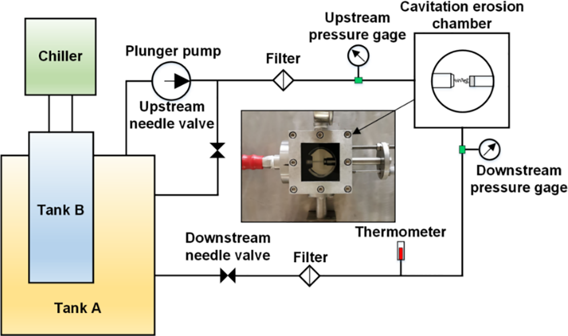
Figure 1: Schematic of the experimental rig for testing cavitation erosion of Al5083 specimens induced by submerged cavitating waterjet
An OHAUS EX125ZH electronic analytical balance with an accuracy of 0.01 mg was used to measure the mass of the specimens before and after cavitation treatment. A Nikon SMZ25 stereomicroscope, an FEI Nova Nano 450 field emission scanning electron microscope, an LEXT OLS 4100 laser scanning microscope were used to observe and describe the surface morphology and structure of the tested specimens. A measurement of Vickers hardness was performed using the FM-ARS900 fully automatic microhardness tester. During the experiment, the specimens were taken out at different cavitation treatment time from the cavitation erosion chamber for mass measurement and surface observation.
2.2 Preparation of Al5083 Specimens
The Al5083 bars were cut using the line-wire cutting machine. Then, the products were processed using the computer numerical control (CNC) machine. The obtained specimens were polished sequentially with SiC papers of 800# to 3000#, followed by a further polishing with a 1.0 μm diamond spray polishing agent. Subsequently, the specimens were cleaned through ultrasonic waves for 15 min in anhydrous ethanol. Then, the specimens were dried using a blower and weighted with the electronic analytical balance. The chemical composition and main mechanical properties of Al5083 are listed in Tables 1 and 2, respectively.


The intensity of cavitation erosion depends on the combinative effect of multiple parameters such as waterjet velocity, impingement angle and standoff distance [18]. Regarding the presented experimental rig, main operating parameters except the standoff distance have been predefined according to the ASTM G134 standard. To determine the optimum standoff distance and examine the operating stability of the experimental rig, A1070 specimens were selected for the preliminary experiment. At T = 20°C and σ = 0.014, five standoff distances ranging from 15.0 to 19.0 mm were selected. The cavitation treatment time was set to 5 min. The cumulative mass loss (∆m) of the specimens is plotted in Fig. 2a against the standoff distance. At s = 16.0 mm, the greatest cumulative mass loss is obtained. At s < 16.0 mm, cavitation bubbles have not grown sufficiently when the waterjet stream impacts the specimen surface. At s > 16.0 mm, some cavitation bubbles have collapsed before they reach the specimen surface. Therefore, s = 16.0 mm was adopted in subsequent experiments.
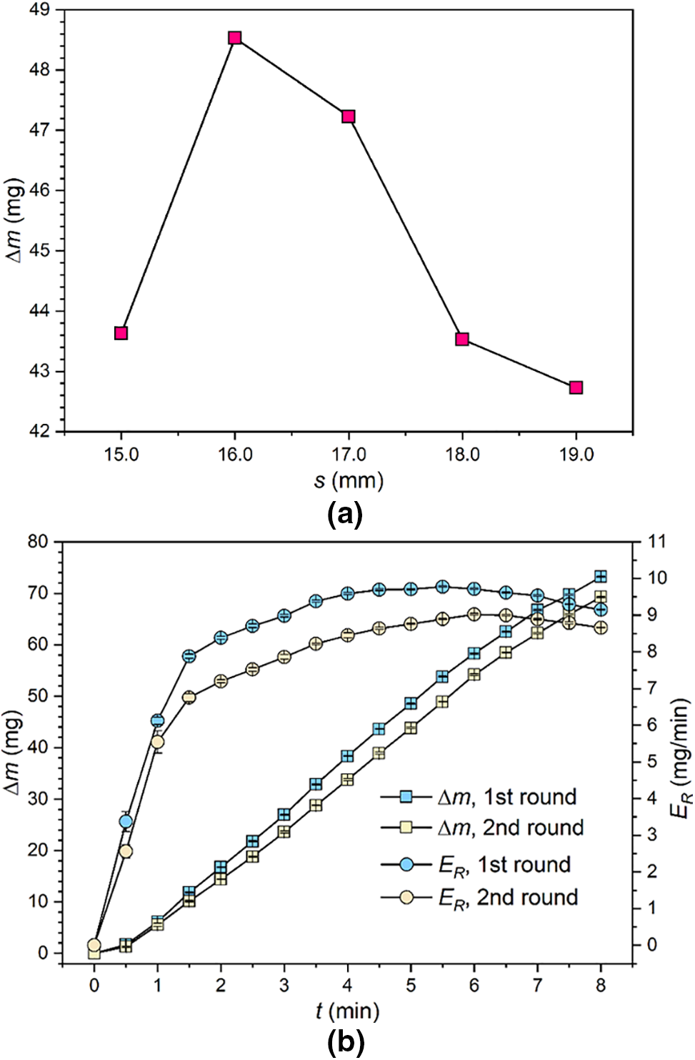
Figure 2: (a) Variation of cumulative mass loss of A1070 specimens with standoff distance; (b) Variation of cumulative mass loss rate with cavitation treatment time
At T = 20°C, σ = 0.014, and s = 16.0 mm, the A1070 specimens were treated with cavitating waterjet for 8 min, and the cumulative mass loss was measured with a time interval of 0.5 min. Two rounds of experiment were conducted. The results are diagrammed in Fig. 2b. With increasing cavitation erosion time, the cumulative mass loss increases continuously, and a nearly linear relation is evidenced. The cumulative mass loss rate (ER = ∆m/t) is also plotted in Fig. 2b. The four characteristic stages, namely incubation, acceleration, stabilization and attenuation stages of cavitation erosion, are evidenced with the variation of ER. For the two rounds of experiments, the periods corresponding to each stage are close to each other. Furthermore, the deviation between ∆m or ER between the results obtained with the two rounds of experiments is less than 5%. Based on a comparison of the results of the two rounds of experiments, the high stability of the experimental rig is demonstrated.
The Al5083 specimens were tested at s = 16.0 mm and σ = 0.014. Three liquid temperatures of 30°C, 40°C and 50°C were adopted. The obtained cumulative mass loss is plotted against the cavitation treatment time in Fig. 3. With increasing cavitation treatment time, the cumulative mass loss increases continuously, and such a tendency is insensitive to liquid temperature [19]. Moreover, when the cavitation treatment time is certain, the cumulative mass loss increases with liquid temperature. High liquid temperature is responsible for high saturated vapor pressure, which facilitates the occurrence of cavitation.
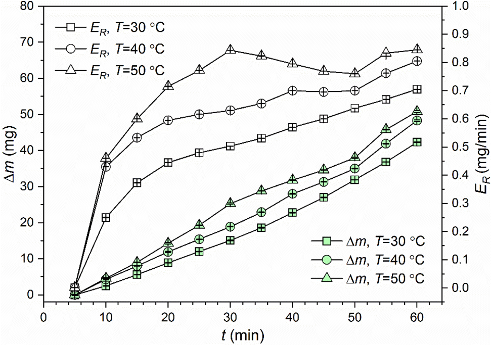
Figure 3: Variations of cumulative mass loss and cumulative mass loss rate of Al5083 specimens with cavitation treatment time at different liquid temperatures
For the cumulative mass loss rate, the difference between the three cases is explicit, as indicated in Fig. 3. At T = 50°C, the acceleration stage of cavitation erosion is terminated at t = 30 min, which is earlier than its counterparts. Then ER decreases rapidly until t = 50 min. Subsequently, ER increases again, as shown in Fig. 3. Similar situation is observed at T = 40°C. In this case, variations of ER exhibit fluctuations at high liquid temperatures. In comparison, at T = 30°C, the time-dependent ∆m and ER are similar to those obtained at room temperature. According to time-dependent ER obtained at T = 30°C, the stabilization stage of cavitation erosion has not yet been reached at t = 60 min. Literally, the cumulative mass loss rate represents the speed of material removal. At T = 30°C, although the material is removed at a relatively low speed, ER increases monotonically with t. In comparison, fluctuations of ER arise at the stabilization stage of cavitation erosion for the cases of T = 40°C and 50°C. It is predictable that high speed of material removal cannot be maintained as the production of cavitation bubbles is promoted.
At each liquid temperature, surface morphology of the specimens treated with cavitating waterjet for 10, 40 and 60 min is illustrated in Fig. 4. According to Fig. 3, t = 10 min is covered in the acceleration stage of cavitation erosion, as is common for the three cases. At this moment, the central part with less severe cavitation erosion is recognizable, as is particularly clear for T = 30°C and 40°C. The erosion ring is still discernible. At t = 40 min, the central part has been eroded, as seen in Fig. 4b,e,h. At such a moment, the overall eroded zone expands relative to those observed at t = 10 min. Furthermore, the profile of the eroded zone deviates from the generally acknowledged circular shape [20]. At t = 60 min, no smooth element is detected in the eroded zone. Some bulges are distributed randomly but assume a large portion of the surface area.
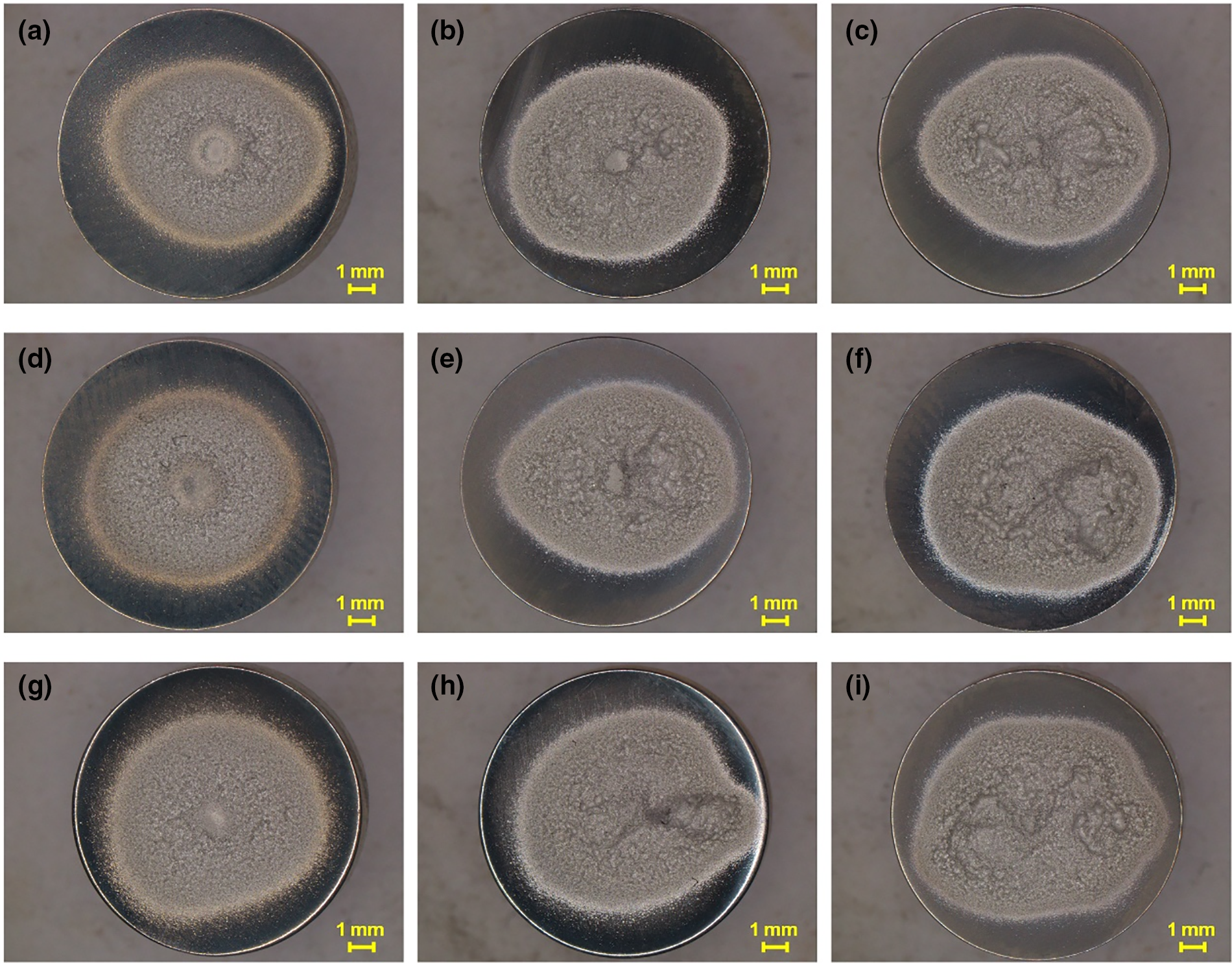
Figure 4: Overall surface morphology of Al5083 specimens treated for different cavitation treatment time at different liquid temperatures: (a) T = 30°C, t = 10 min; (b) T = 30°C, t = 40 min; (c) T = 30°C, t = 60 min; (d) T = 40°C, t = 10 min; (e) T = 40°C, t = 40 min; (f) T = 40°C, t = 60 min; (g) T = 50°C, t = 10 min; (h) T = 50°C, t = 40 min; (i) T = 50°C, t = 60 min
As cavitation treatment proceeds, the difference of local surface morphology in the whole cavitation erosion zone is intensified, as shown in Fig. 4. In Fig. 4c,f,g, some erosion pits are characterized by large size but are not located near the center of the specimen. In this situation, the distribution of cavitation bubbles in the waterjet stream is non-uniform, so the impact loads acting on the specimen surface are not even. Moreover, cavitation clouds produced with the development of waterjet are intermittent, which enhances the randomness of the loads imposed on the specimen surface [21]. Meanwhile, the physical properties of the target material influence cavitation erosion. For the material Al5083 used in the presented experiment, its elastic modulus and hardness are relatively low (see Table 2). When it is impacted by the loads emitted with the collapse of cavitation bubbles, the generation of irregularly distributed cavitation erosion pits over the specimen surface is reasonable.
At T = 40°C, the distribution of surface heights over the monitored elements was acquired using the laser confocal microscope at t = 10, 40 and 60 min. In consideration of the attainable resolutions, elements are separately monitored in the central and the erosion zones, and typical surface morphology is illustrated in Fig. 5. The morphology presented is representative and was selected based on the results obtained with repeated experiments. At t = 10 min, the central zone is dominated with plastic deformation, while in the cavitation erosion zone, tiny erosion pits are detected. As t increases to 40 min, the central zone protrudes remarkably, as seen in Fig. 5c. In this situation, the plastic deformation is intensified, and the surface elements in the central zone are squeezed by adjacent surface elements. At this moment, the cavitation erosion zone is characterized by material removal in the form of large elements, as shown in Fig. 5d. Moreover, the depth of the large erosion pit shown in Fig. 5d is great, as is judged from the comparison between the colors indicating the surface heights. At t = 60 min, the surface morphology of the central and eroded zones is similar, as shown in Fig. 5e,f. Essentially, for the cavitation erosion zone, the material has shed from the substrate in the pattern of large pieces.
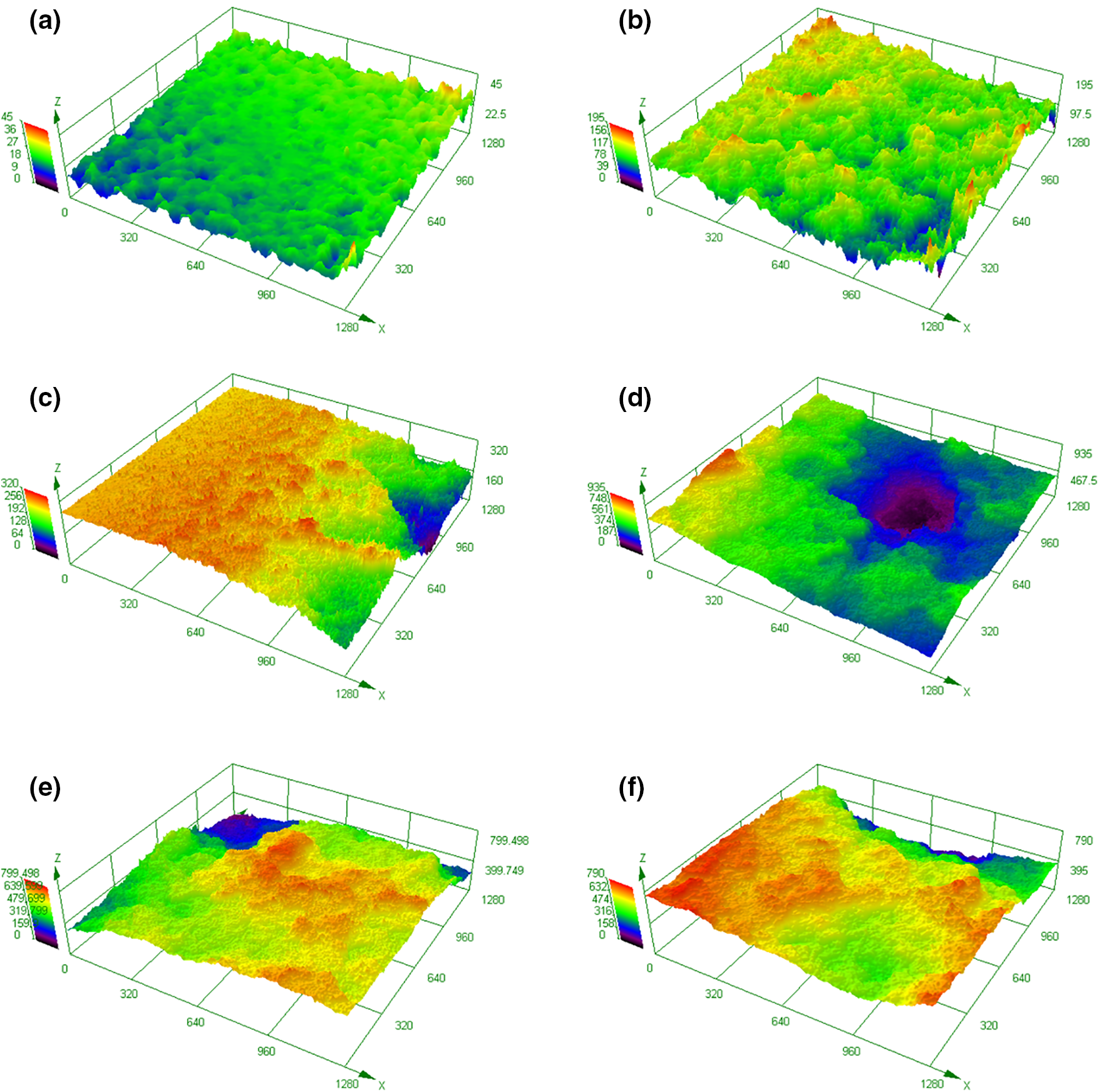
Figure 5: Local surface morphology of Al5083 specimens treated for different cavitation treatment time at T = 40°C: (a) t = 10 min, central zone; (b) t = 10 min, erosion zone; (c) t = 40 min, central zone; (d) t = 40 min, erosion zone; (e) t = 60 min, central zone; (f) t = 60 min, erosion zone
SEM images of the cavitation erosion zone on the surface of the specimens treated at different liquid temperatures are shown in Fig. 6. At T = 30°C and t = 10 min, cavitation erosion is relatively slight, as indicated in Fig. 6a, and the surface is dominated with plastic deformation and tiny erosion pits. In this case, the surface remains smooth, as is similar to that obtained at room temperature. As cavitation treatment proceeds, as shown in Fig. 6b, the number of large cavitation erosion pits increases, and the surface roughness increases accordingly. Such a pattern of damage differs considerably from that induced by the treatment of ultrasonic cavitation, which exhibits fatigue spalling of the surface layer [22]. Moreover, the size of the erosion pits is not uniform. The erosion pits are further enlarged at t = 60 min, as seen in Fig. 6c. The same tendency is evidenced at T = 40°C. For the case of T = 50°C, the surface has been severely eroded at t = 10 min, and pits and cracks prevail, as shown in Fig. 6g. With increasing cavitation treatment time, large erosion pits resulting from the merging of small erosion pits are produced, and the pit size is much larger than those obtained at T = 30°C and 40°C, as is consistent with the comparison of the cumulative mass loss illustrated in Fig. 3.
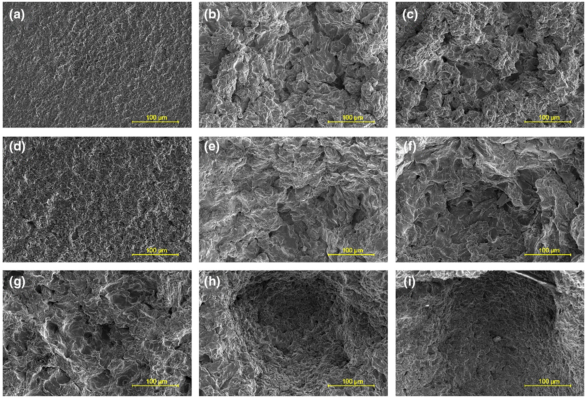
Figure 6: SEM images of surface elements in cavitation erosion zone obtained under different operating conditions: (a) T = 30°C, t = 10 min; (b) T = 30°C, t = 40 min; (c) T = 30°C, t = 60 min; (d) T = 40°C, t = 10 min; (e) T = 40°C, t = 40 min; (f) T = 40°C, t = 60 min; (g) T = 50°C, t = 10 min; (h) T = 50°C, t = 40 min; (i) T = 50°C, t = 60 min
3.3 Cross-Sectional Microhardness
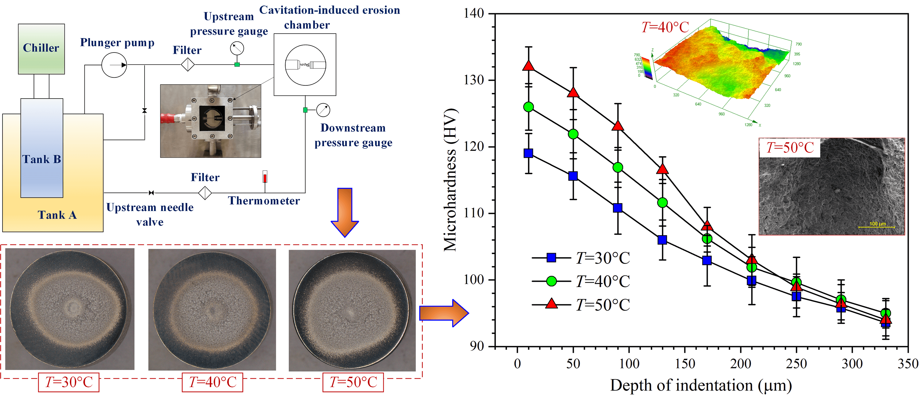
Generally, the strengthening effect is evaluated through the cross-sectional microhardness [23]. At t = 60 min, cross-sectional microhardness measured for the specimens treated at T = 30°C, 40°C and 50°C is plotted in Fig. 7. For the measurement, the specimens were cut apart, and the cross sections perpendicular with the target surface were disclosed. Over the cross sections, the measurement points were deployed in the depth direction, and the first measurement point was positioned at a distance of 10 µm from the target surface. It is demonstrated in Fig. 7 that cavitation treatment stimulates an explicit hardening effect for the Al5083 specimens. Moreover, the maximum microhardness increases with the liquid temperature. The thickness of the hardened layer is about 200 µm. In this context, although T = 30°C corresponds to the lowest overall microhardness, the decline of microhardness in the depth direction is the most moderate.
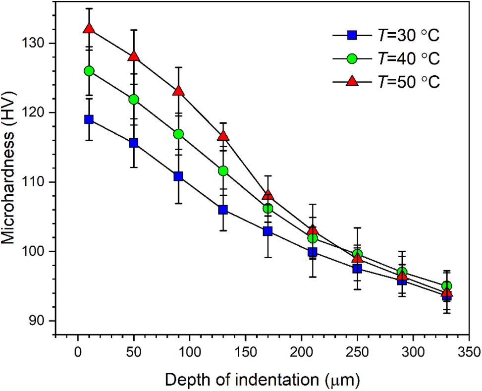
Figure 7: Variation of cross-sectional microhardness with liquid temperature after cavitation treatment of 60 min
At T = 50°C, microhardness decreases rapidly as the depth of indentation increases. In this case, material is significantly removed from the target surface, as implies that the surface layer with high microhardness sheds continuously from the substrate, and the surface is thereby replaced with that sealed underneath the target surface. From another perspective, cavitation erosion pits assume the function of absorbing the energy released with the collapse of cavitation bubbles. The effects of the accumulation of the energy lie in two aspects; one is material removal in large pieces, and the other is the development of microhardness in depth direction. Therefore, overall microhardness increases with liquid temperature.
4 Cavitation Erosion Mechanism
Under the waterjet cavitation treatment, different materials exhibit different characteristics of surface structure and mechanical performance, as depends significantly on physical properties of the materials. Moreover, as cavitation treatment proceeds, the accumulation of the energy absorbed by the impacted specimen can incur structural variation or even phase transformation. Therefore, it is difficult to compare the response of different materials to cavitation treatment. The material considered in the presented study is an Al-Mg alloy with a relatively high content of Mg. The addition of Mg leads to an increase in the microhardness. Mg is dissolved in α phase. Such a material is featured by regularly arranged grain boundaries and the absence of dendrite [24]. Generally, the plastic deformation under the impact of the loads released with the collapse of cavitation bubbles is determined by dislocation slip. In comparison, at high environment temperatures, recovery and recrystallization will arise, resulting in the degradation of the compactness of the inner structure. With the accumulation of the absorbed energy in the specimen, the dislocation wall is converted into subgrain boundaries, and dislocation cells are replaced with subgrains, implying that the grains are refined. Therefore, a properly selected combination of operating parameters is beneficial for the improvement of the ability of anti-deformation.
Al-Mn-Fe and Mg-Si intermetallic compounds exist at grain boundaries, as causes high hardness but low plasticity. When the energy received exceeds the elastic limit, stress accumulation occurs at grain boundaries, and the phase containing Mg with relatively low plasticity will shed from the substrate first, as serves as the source of cracks. Moreover, dislocations accumulate in some depth, and the cracks develop in lateral directions. When cavitation treatment proceeds, the cracks with different orientations interact and merge with each other, resulting in material removal in the form of large pieces.
An increase in liquid temperature promotes the generation of cavitation bubbles. However, the collapse of cavitation bubbles is closely related to the bubble size, which is significantly influenced by the liquid temperature. As liquid temperature increases, the collapse of some bubbles with large size may not induce an impact on the target surface [25]. In this situation, the possibility for the motion of cavitation bubbles to deviate from the waterjet stream increases. Furthermore, the characteristics of cavitation are closely related to the development of the waterjet stream. At normal liquid temperature, ring-like cavitation clouds impact the specimen surface, which induces the formation of an erosion ring. However, based on the surface morphology obtained at high liquid temperatures, the erosion ring is not evident, implying that cavitation bubbles prevail over the whole cross section of the waterjet stream. From another perspective, the waterjet stream is disturbed by swarms of cavitation bubbles, and the directionality of bubble motion declines. Essentially, the generation of cavitation clouds is intermittent, so is the collapse of cavitation bubbles near the specimen surface. In this situation, the impact loads acting on the specimen surface are non-uniform and discontinuous. With the proceeding of the cavitation treatment, originally tiny erosion pits expand, and some neighboring pits merge with each other. When the collapse of cavitation bubbles occurs inside relatively large erosion pits, the implosion effect can damage the inner wall of the pits, and so these pits are enlarged further.
(1) The liquid temperature imposes a significant effect on cavitation erosion of Al5083 specimens. When liquid temperature increases from 30°C to 50°C, the cumulative mass loss increases monotonically.
(2) The profile of the cavitation erosion zone is irregular. An ablation-like pattern is demonstrated when the specimen is impacted by cavitating waterjet of high temperatures. Increasing liquid temperature promotes the generation of cavitation bubbles, and the randomness of the distribution of cavitation bubbles is intensified as well.
(3) At a liquid temperature of 30°C, and at the initial stage of cavitation erosion, plastic deformation and tiny erosion pits are predominant. At a liquid temperature of 50°C, severe cavitation erosion occurs as the specimen is treated for 10 min. As the cavitation treatment extends, the surface is possessed by erosion pits of various sizes, and large erosion pits are produced.
(4) Overall cross-sectional microhardness increases with liquid temperature. The maximum microhardness is close to the target surface. At a liquid temperature of 50°C, the thickness of the hardened layer is the smallest, but the maximum microhardness is the highest among the three cases. Due to material removal, the surface layer with high microhardness continuously sheds from the substrate.
In engineering applications, cavitation erosion is much more complex than that observed in laboratory. Regarding the mechanical components exposed to the cavitation nurtured in a liquid of high temperature, flow velocity near the components should be lowered, and the application of materials of high hardness or surface coating for resisting cavitation erosion is advised. Since diverse materials and operating conditions are used in practical engineering, a more extensive study on the response of materials to cavitation treatment is expected.
Acknowledgement: The authors also thank Jiangsu Key Laboratory of Materials and Tribology for providing assistance in the test of cross-sectional microhardness.
Funding Statement: The authors are grateful for the financial support of National Natural Science Foundation of China (Grant Nos. 52311540154 and 52175410).
Author Contributions: The authors confirm contribution to the paper as follows: Study conception and design: Can Kang and Haixia Liu; data collection: Shifeng Yan; analysis and interpretation of results: Can Kang, Haixia Liu, Shifeng Yan, Jie Chen and Kejin Ding; draft manuscript preparation: Shifeng Yan and Jie Chen. All authors reviewed the results and approved the final version of the manuscript.
Availability of Data and Materials: The authors confirm that the data supporting the findings of this study are available within the article.
Ethics Approval: Not applicable.
Conflicts of Interest: The authors declare that they have no conflicts of interest to report regarding the present study.
References
1. Fu M, Ge H. Numerical analysis of the iridescent ring around cavitation erosion pit on stainless steel surface. J Fluids Eng. 2016;138(9):091101. doi:10.1115/1.4033294. [Google Scholar] [CrossRef]
2. Kang C, Liu H, Zhang T, Li Q. Investigation of submerged waterjet cavitation through surface property and flow information in ambient water. Appl Surf Sci. 2017;425(3):915–22. doi:10.1016/j.apsusc.2017.07.115. [Google Scholar] [CrossRef]
3. Liu X, Long Z, He J, Liu X, Hou Y, Lu J, et al. Temperature effect on the impact of a liquid-jet against a rigid boundary. Optik. 2013;124(13):1542–6. doi:10.1016/j.ijleo.2012.04.020. [Google Scholar] [CrossRef]
4. De Giorgi MG, Bello D, Ficarella A. Analysis of thermal effects in a cavitating orifice using Rayleigh equation and experiments. J Eng Gas Turb Power. 2010;132(9):092901. doi:10.1115/1.4000367. [Google Scholar] [CrossRef]
5. Nagalingam AP, Yeo SH. Effects of ambient pressure and fluid temperature in ultrasonic cavitation machining. Int J Adv Manuf Technol. 2018;98(9–12):2883–94. doi:10.1007/s00170-018-2481-0. [Google Scholar] [CrossRef]
6. Li Z, Han J, Lu J, Zhou J, Chen J. Vibratory cavitation erosion behavior of AISI304 stainless steel in water at elevated temperatures. Wear. 2014;321:33–7. doi:10.1016/j.wear.2014.09.012. [Google Scholar] [CrossRef]
7. De Giorgi MG, Ficarella A, Tarantino M. Evaluating cavitation regimes in an internal orifice at different temperatures using frequency analysis and visualization. Int J Heat Fluid Flow. 2013;39(6):160172. doi:10.1016/j.ijheatfluidflow.2012.11.002. [Google Scholar] [CrossRef]
8. Hattori S, Komoriya I, Kawasaki S, Kono S. Cavitation erosion of silver plated coatings in a low-temperature environment. Wear. 2012;292–293(9):74–81. doi:10.1016/j.wear.2012.05.031. [Google Scholar] [CrossRef]
9. Xu Z, Li Z, Xu Z, Ma Z, Chen S, Liu X, et al. Avoiding degradation and increasing joint strength of Al alloys by rapid ultrasonic soldering at low temperature. J Mater Process Technol. 2022;300(4):117397. doi:10.1016/j.jmatprotec.2021.117397. [Google Scholar] [CrossRef]
10. Golykh RN, Khmelev VN, Barsukov RV. Influence of temperature and phase transitions on cavitation in liquids. J Phys: Conf Ser. 2020;1679(2):022069. doi:10.1088/1742-6596/1679/2/022069. [Google Scholar] [CrossRef]
11. Hutli E, Nedeljkovic MS, Bonyár A, Légrády D. Experimental study on the influence of geometrical parameters on the cavitation erosion characteristics of high speed submerged jets. Exp Therm Fluid Sci. 2017;80(8):281–92. doi:10.1016/j.expthermflusci.2016.08.026. [Google Scholar] [CrossRef]
12. Fahim J, Hadavi SMM, Ghayour H, Tabrizi S.A. H. Cavitation erosion behavior of super-hydrophobic coatings on Al5083 marine aluminum alloy. Wear. 2019;424–425(6):122–32. doi:10.1016/j.wear.2019.02.017. [Google Scholar] [CrossRef]
13. Zhang J, Wang J, Zhang B, Zeng Y, Duan J, Hou B. Fabrication of anodized superhydrophobic 5083 aluminum alloy surface for marine anti-corrosion and anti-biofouling. J Oceanol Limnol. 2020;38(4):1246–55. doi:10.1007/s00343-020-0036-3. [Google Scholar] [CrossRef]
14. Jain VKS, Yazar KU, Muthukumaran S. Development and characterization of Al5083-CNTs/SiC composites via friction stir processing. J Alloys Comp. 2019;798:82–92. doi:10.1016/j.jallcom.2019.05.232. [Google Scholar] [CrossRef]
15. Alizadeh A, Khayami A, Karamouz M, Hajizamani M. Mechanical properties and wear behavior of Al5083 matrix composites reinforced with high amounts of SiC particles fabricated by combined stir casting and squeeze casting; A comparative study. Ceram Int. 2022;48(1):179–89. doi:10.1016/j.ceramint.2021.09.093. [Google Scholar] [CrossRef]
16. ASTM G134. Standard test method for erosion of solid materials by cavitating liquid jet. 2017. Available from: www.astm.org. [Accessed 2024]. [Google Scholar]
17. Liu H, Kang C, Soyama H. Experimental study of the influence of test chamber dimensions on aggressive intensity of the cavitating jet. J Test Eval. 2020;48(5):3588–601. doi:10.1520/JTE20180573. [Google Scholar] [CrossRef]
18. Jha S, Singh V, Kumar V, Bansal A, Singh J, Singla AK, et al. Microstructure, wettability, cavitation and corrosion performance of aluminum (Al6061) coated with RF-sputtered AlN thin film. Surf Coat Technol. 2024;489(8):131168. doi:10.1016/j.surfcoat.2024.131168. [Google Scholar] [CrossRef]
19. Peng K, Qin FGF, Jiang R, Kang S. Interpreting the influence of liquid temperature on cavitation collapse intensity through bubble dynamic analysis. Ultrason Sonochem. 2020;69:105253. doi:10.1016/j.ultsonch.2020.105253. [Google Scholar] [PubMed] [CrossRef]
20. Liu H, Chen J, Chen J, Liu G. Characteristics of waterjet cavitation erosion of 304 stainless steel after corrosion in NaCl solution. Acta Metall Sin. 2020;56(10):1377–85. doi:10.11900/0412.1961.2020.00107. [Google Scholar] [CrossRef]
21. Hosbach M, Skoda R, Sander T, Leuteritz U, Pfitzner M. On the temperature influence on cavitation erosion in micro-channels. Exp Therm Fluid Sci. 2020;117(5):110140. doi:10.1016/j.expthermflusci.2020.110140. [Google Scholar] [CrossRef]
22. Pan C-C, Xia D-H, Hou M-Y, Qin Z, Xu Y, Behnamian Y, et al. Cavitation erosion of the AA7050 aluminum alloy in 3.5 wt% NaCl solution—part 1: mitigating effect by corrosion. Corros Sci. 2024;232:112012. doi:10.1016/j.corsci.2024.112012. [Google Scholar] [CrossRef]
23. Zhou M, Liu H, Kang C, Wei X. Resistance of curved surfaces to the cavitation erosion produced through high-pressure submerged waterjet. Wear. 2020;440:203091. doi:10.1016/j.wear.2019.203091. [Google Scholar] [CrossRef]
24. Mahmoodi M, Naderi A, Dini G. Correlation between structural parameters and mechanical properties of Al5083 sheets processed by ECAR. J Mater Eng Perform. 2017;26:6022–7. doi:10.1007/s11665-017-3021-z. [Google Scholar] [CrossRef]
25. Dular M. Hydrodynamic cavitation damage in water at elevated temperatures. Wear. 2016;346–347:78–86. [Google Scholar]
Cite This Article
 Copyright © 2024 The Author(s). Published by Tech Science Press.
This work is licensed under a Creative Commons Attribution 4.0 International License , which permits unrestricted use, distribution, and reproduction in any medium, provided the original work is properly cited.


 Submit a Paper
 Propose a Special lssue
 View Full Text
 Download PDF
 Downloads
 Citation Tools