 Open Access
ARTICLE
Influence of Blade Number on the Performance of Hydraulic Turbines in the Transition Stage
1 School of Energy and Power Engineering, Lanzhou University of Technology, Lanzhou, 730050, China
2 Key Laboratory of Fluid Machinery and Systems of Gansu, Lanzhou, 730050, China
* Corresponding Author: Guangbiao Zhao. Email:
Fluid Dynamics & Materials Processing 2024, 20(11), 2617-2636. https://doi.org/10.32604/fdmp.2024.053186
Received 26 April 2024; Accepted 30 July 2024; Issue published 28 October 2024
Abstract
To analyze the effect of blade number on the performance of hydraulic turbines during the transient stage in which the flow rate is not constant, six hydraulic turbines with different blade numbers are considered. The instantaneous hydraulic performance of the turbine and the pressure pulsation acting on the impeller are investigated numerically by using the ANSYS CFX software. The ensuing results are compared with the outcomes of experimental tests. It is shown that the fluctuation range of the pressure coefficient increases with time, but the corresponding range for the transient hydraulic efficiency decreases gradually when the flow velocity transits to larger values. During the transition to small flow velocity, the fluctuation range of the pressure coefficient gradually decreases as time passes, but the corresponding fluctuation range of its transient hydraulic efficiency gradually becomes larger. The fluctuation range in the Z9 case is small during the transition. The main frequency of transient hydraulic efficiency pulsation is equal to the blade frequency. At the main frequency, Z7 has the largest amplitude of the hydraulic efficiency pulsation, Z10 has the smallest amplitude, and the difference between Z7 and Z9 is limited. As the number of blades grows, the pressure pulsation during the transition process gradually decreases, but the pressure pulsation of Z10 at the volute tongue is larger. In the steady state, Z9 has the highest efficiency and in the transient stage, the pressure coefficient fluctuation range is small. Accordingly, for the hydraulic turbine Z9, the performance is optimal.Keywords
Nomenclature
| D1 | Impeller inlet diameter (mm) |
| D2 | Impeller outlet diameter (mm) |
| b2 | Inlet width (mm) |
| Z | Impeller outlet diameter (mm) |
| D3 | Volute base circle diameter (mm) |
| b3 | Volute outlet width (mm) |
| D | Volute inlet diameter (mm) |
| Greek Symbols | |
| | Inlet placement corner (°) |
| | Blade inlet angle (°) |
| | Material density (kg · m−3) |
| | Poisson ratio |
| | Elasticity modulus (GPa) |
In industrial production, there is a large amount of liquid residual pressure energy. Centrifugal pumps as hydraulic turbines are a common hydraulic turbine device, because its simple structure, diverse forms, convenient operation and other characteristics, is widely used in petrochemicals, desalination and other industrial production to recover this part of the residual pressure energy. When the centrifugal pump is used to reverse the operation of the hydraulic turbine in the inertial coordinate system, the flow inside the hydraulic turbine is non-constant flow (also called transient flow), which can be divided into two categories due to different operating conditions, one is the transient flow inside the hydraulic turbine under stable operating conditions; the other is the transient flow in the rapid transition process, in which the flow parameters are changed drastically in a short period of time. The transient flow inside the hydraulic turbine can cause pressure pulsation inside the turbine, which makes vibration and noise during the operation of the hydraulic turbine, and it may even cause the hydraulic turbine unit to fail to operate properly and affect its service life. Therefore, it is necessary to conduct in-depth research on the hydraulic performance and pressure pulsation of hydraulic turbines [1–3].
At present, scholars have studied the transient flow in the transition process of hydraulic machinery [4–7]. Si et al. [8] adopted a numerical simulation method to explore the multistage pump shutdown hydraulic transition process internal transient characteristics, and the results indicate that the multi-stage pump shared four conditions during unplanned shutdown, pumping, braking, reversing and runaway. The research about the pressure pulsation of hydraulic turbines mainly focuses on the numerical calculation and experimental study of pressure pulsation in each cross-flow component of hydraulic turbines under different working conditions [9–11]. In addition, the influence of the radial clearance between the impeller and the volute, the number of blades and guide vanes on the pressure pulsation in each cross-flow component has also been studied [12,13], and most of the current studies on pressure pulsation focus on the inside of the hydraulic turbine under stable operating conditions. There are few studies on the pressure pulsation caused by the transient flow in the rapid transition process. The impeller is the core component of the hydraulic turbine, and the number of blades is one of the important parameters, so there are many studies on the effect of the variation of the number of blades on the performance of the hydraulic turbine. For example, in order to reduce the energy loss of rocket turbopump, non-stationary transient simulation of impeller and diffuser with different numbers of blades, Akihito et al. [14] found that the energy loss is minimized when the number of impeller blades is 10 + 10, and the number of diffuser blades is 11; Li et al. [15] studied the effect of different guide vane numbers on the transient pressure pulsation of submersible pumps by numerical simulation and found that the pulsation amplitude increased with the increase of guide vane numbers when the number of guide vane blades was 6 through non-stationary numerical simulation. Li et al. [16] claimed that the increase in the number of blades can effectively suppress the unsteady flow and velocity mutation in the impeller clearance region; Gamal et al. [17] found that the 7-blade model has the highest efficiency, and the increase in the number of blades reduces the secondary flow in a certain limit, thus the loss is reduced. However, too many blades can increase the internal friction loss of the hydraulic turbine, which makes the efficiency decrease instead. The number of blades is one of the main factors affecting the pressure and velocity distribution in a hydraulic turbine. However, most of the existing studies concentrate on the effect of performance under stable operating conditions, and there are few studies on the rapid transition process. Literature [18,19] found that there exists an optimal number of blades to minimize the radial force on the hydraulic turbine during the transient transition to improve the stability of turbine operation due to excessive radial force. By studying the effect of the number of vanes on the radial force during the transition process of the core main pump with variable flow rate, literature [20] found that the value of radial force on the impeller of the core main pump increases with the increase of blade number and flow rate when changing the blade number, and the value reaches the maximum when the number is 7. Therefore, it is of great significance to study the influence of different blade numbers on the hydraulic performance of a hydraulic turbine in the transition process of variable flow for the safe and reliable operation of a hydraulic turbine.
In this paper, the IS80-50-315 centrifugal pump reverse acting turbine is taken as the research object. On the basis of using external characteristic experiments to verify the correctness of the numerical calculation method, the transient process of the hydraulic turbine from the optimal operating condition (QBEP) to the low flow operating condition (0.76QBEP) and from the optimal operating condition (QBEP) to the large flow operating condition (1.24QBEP) is numerically simulated to analyze the impact of blade number changes on the instantaneous hydraulic performance and pressure pulsation of a hydraulic turbine by changing the number of blades. The analysis results can provide a basic reference for the stable and safe operation of the hydraulic turbine.
2 The Main Geometric Parameters of Hydraulic Turbine
In this paper, the IS80-50-315 low specific speed centrifugal pump (ns = 33) reversing for hydraulic is the research object, as shown in Fig. 1. The original external characteristic parameters of the centrifugal pump are: QP = 25 m3/h, head H = 32 m, n = 1450 r/min. The main geometrical parameters of the hydraulic turbine is shown in Table 1 [21]. Table 1: Geometrical parameters of the fluid turbine from [21]. Copyright ©2018, IOP Journal of Mechanical Engineering Publishing.
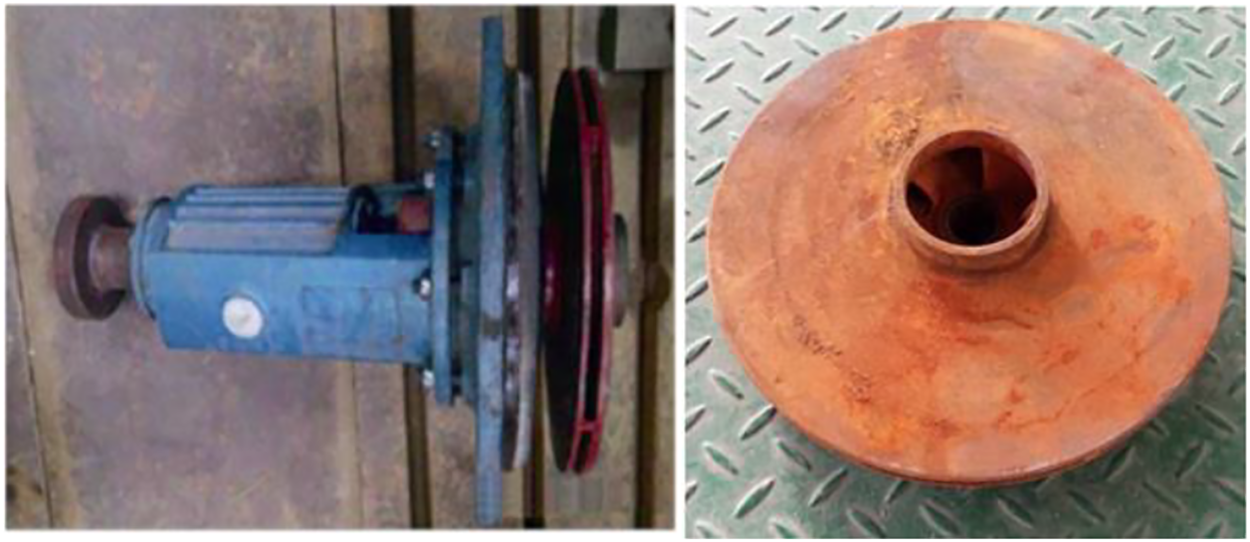
Figure 1: IS80-50-315 centrifugal pump

3.1 Calculation Domain Selection and Meshing
According to the main geometrical parameters of the original hydraulic turbine in Table 1, the Pro/Engineer software is used to model each overflow component to obtain the computational domain shown in Fig. 2. For the whole fluid domain, a hexahedral mesh is used for delineation, as shown in Fig. 3.
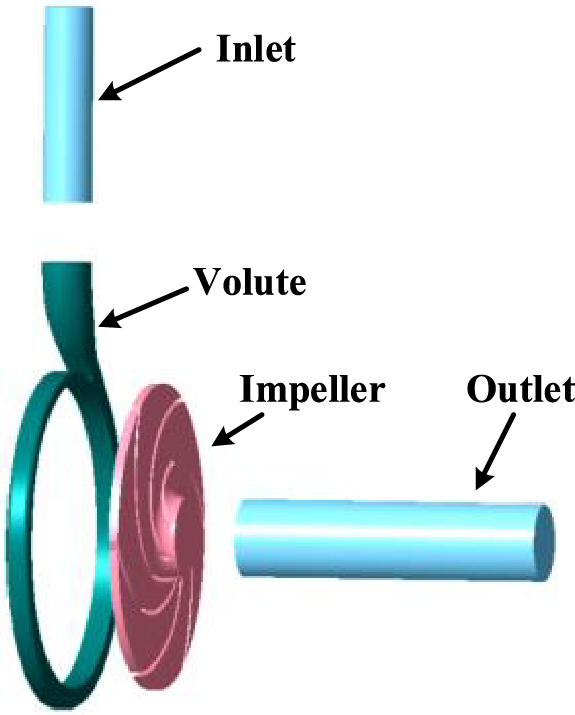
Figure 2: Computational fluid area
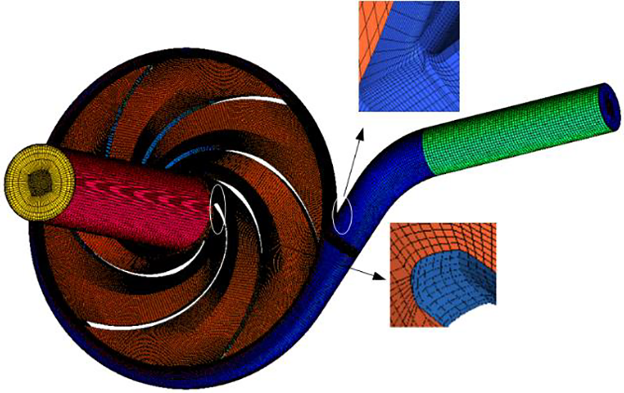
Figure 3: Structured meshing
Different turbulence models are selected, then the applicability of the wall function and the requirement of Y+ value for the mesh in the near-wall region are different. The boundary mesh provided by ICEM-CFD can effectively control the Y+ value. In this paper, the standard k-ε turbulence model is used to solve the internal flow characteristics of the hydraulic turbine, and the Y+ value of its grid nodes from the wall should be controlled in the range of 30 < Y+ < 300 to basically satisfy the quality requirements of the grid near the wall area [22], Fig. 4 is the Y+ value of the grid of the near-wall area of the model, and it can be seen that the Y+ is within the permissible range, and the boundary layer mesh is set up appropriately. Taking the hydraulic efficiency at 2.1QP as a guideline: when the efficiency change is within 0.3%, it can be considered that the mesh has little influence on the performance of the hydraulic turbine, and the finalized mesh number is 3.39 million, as shown in Fig. 5 (Among which the impeller: 1.58 million, the volute: 1.18 million, the Inlet: 0.26 million and the outlet: 0.37 million).
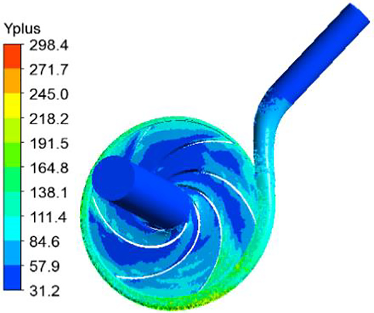
Figure 4: The Y + value of the grid near the wall
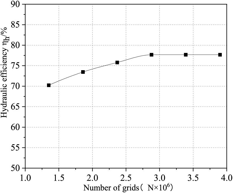
Figure 5: Grid independence test
Considering the internal flow conditions during the operation of the hydraulic turbine, the control equations used for the overflow region are the continuity equation and the momentum conservation equation.
Continuity equation:
In this paper, the study is a pure liquid-phase fluid and is incompressible, and the general form of its continuity equation can be simplified as:
where
Momentum equation (Navier-Stokes equation):
where p indicates pressure;
For the hydraulic turbine in this paper, the flow in the computational domain is incompressible, and the energy equation can be disregarded.
In the transition process of variable flow transient, mass flow rate is used for the hydraulic turbine inlet condition and the outlet boundary condition is set as pressure outlet. In order to ensure the reliability of the results, the impeller internal flow pattern is monitored after running for 0.1 s and quadratic function is adopted for the transition process. According to the change form of this function which transitions to high and low flow conditions, the mass flow rate variation of the inlet is defined by ANSYS CEL custom function language. The describing function is:
where m(t)—inlet mass flow rate, kg/s; m—mass flow rate at optimal operating conditions, kg/s; m0—mass flow rate coefficient, kg/s; t—time, s; t0—initial time, 0.1 s; the inlet condition gives the inlet mass flow rate, and the mass flow rate of the model is controlled by the inlet boundary condition.
In order to ensure the accuracy of the simulation results, the first in the optimal operating conditions run 0.1 s and then to the large flow or small flow transition, in 0.1~1.1 s to the large flow conditions (1.24QBEP) and small flow conditions (0.76QBEP), the transition of the entire transition process took 1 s. These descriptive functions are expressed as the ANSYS CEL customized function language, such as Eqs. (2) and (3) are shown:
Formula:
3.4 Transient Simulation Setting
For the non-constant numerical calculation, the impeller rotates 4° in one time step, thus one time step is equal to 4.6 × 10⁻⁴ s, so the total calculation time is 1.1 s. In this article, the numerical simulation of the hydraulic turbine is carried out by ANSYS CFX software, and the equations used are the Reynolds time-averaged Navier-Stokes (N-S) equations and the standard k-ε turbulence model, which are discretized by the SIMPLEC algorithm, and the discretization formats adopt the second-order windward format in order to make the discretization possible to be reduced. For the whole computational domain, the following parameter settings are made: the medium is set to be 25°C water, the inlet is set to be mass flow rate, the outlet is set to be pressure outlet, the outlet pressure is set to be 0.4 MPa, all the wall surfaces in the computational domain are set to be no-slip wall surfaces, the standard wall function is used near the wall, and the convergence accuracy is set to be 10−6.
4.1 Calculation Accuracy Validation
In order to verify the rationality and accuracy of the numerical calculation method, the external characteristic parameters obtained by numerical calculation are compared with the test results. Based on the hydraulic turbine test sketch shown in Fig. 6a, the test rig for IS 80-50-315 centrifugal pump reversed for the hydraulic turbine is constructed, and the hydraulic turbine test rig is shown in Fig. 6b [21].
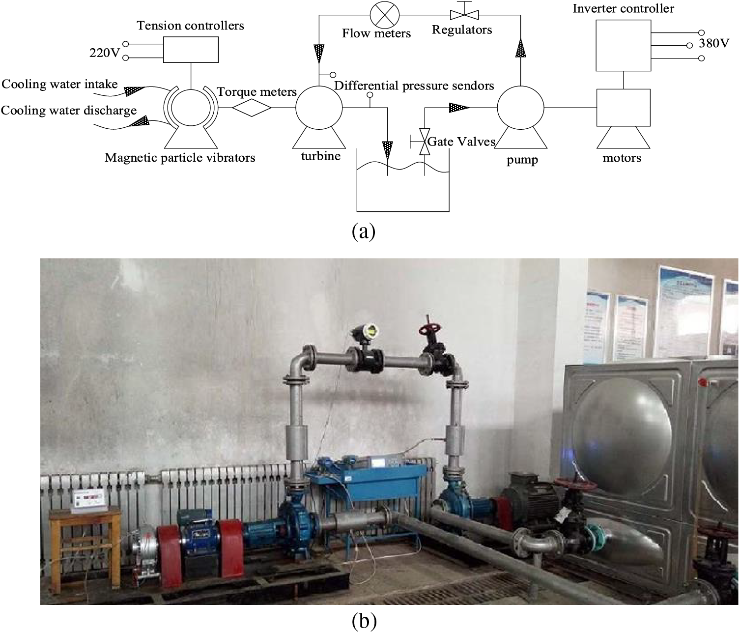
Figure 6: Hydraulic turbine test bench and schematic diagram. (a) Schematic diagram of the hydraulic turbine test bench. (b) Hydraulic turbine test bench
The required flow rate and pressure in the test are provided by the centrifugal pump, and the required test conditions of the hydraulic turbine are satisfied by controlling the regulating valve, the output shaft end of the hydraulic turbine is de-energized by the magnetic powder brake, and various types of measuring instruments and models are shown in Table 2. The hydraulic turbine is tested in the external characteristic test, and the results are shown in Fig. 7. Due to the numerical simulation process does not take into account the impeller before and after the cavity and the import and export pipeline hydraulic loss on the hydraulic turbine, resulting in the simulation of the head is smaller than the test head, simulation efficiency is greater than the test efficiency, the optimal conditions of the two results are relatively close to each other, the trend of the change is similar to each other, and the error is within 5%, which shows that this paper adopts a numerical simulation of the method is feasible.

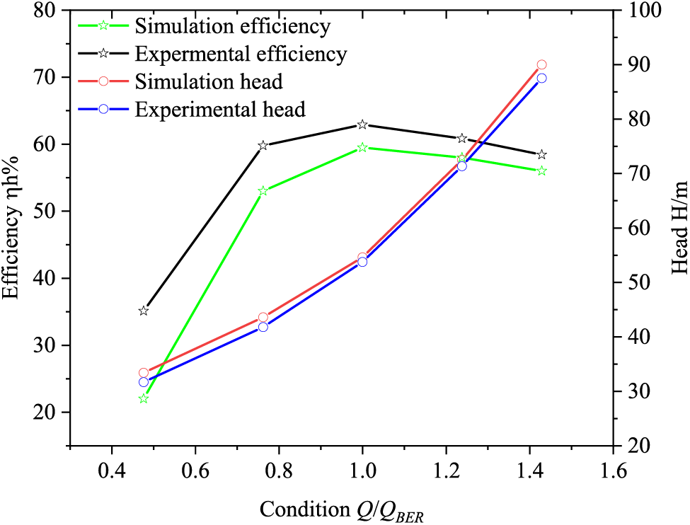
Figure 7: External characteristic curve of hydraulic turbine
4.2 Analysis of External Characteristics
By CFD numerical calculation, the curves of head and hydraulic efficiency with flow rate of hydraulic turbine with different number of blades under different working conditions are obtained, as shown in Fig. 8. As can be seen from Fig. 9, the changing law of different blades number of hydraulic turbine external characteristics is similar, the hydraulic efficiency shows a tendency to increase with increasing flow rate before the optimum condition (QBEP) and decreases with increasing flow rate after the optimum condition (QBEP), and head is slowly rising with the increase of flow rate.
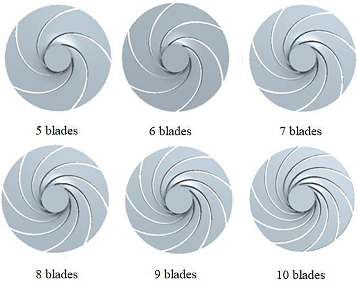
Figure 8: Different blade number impellers
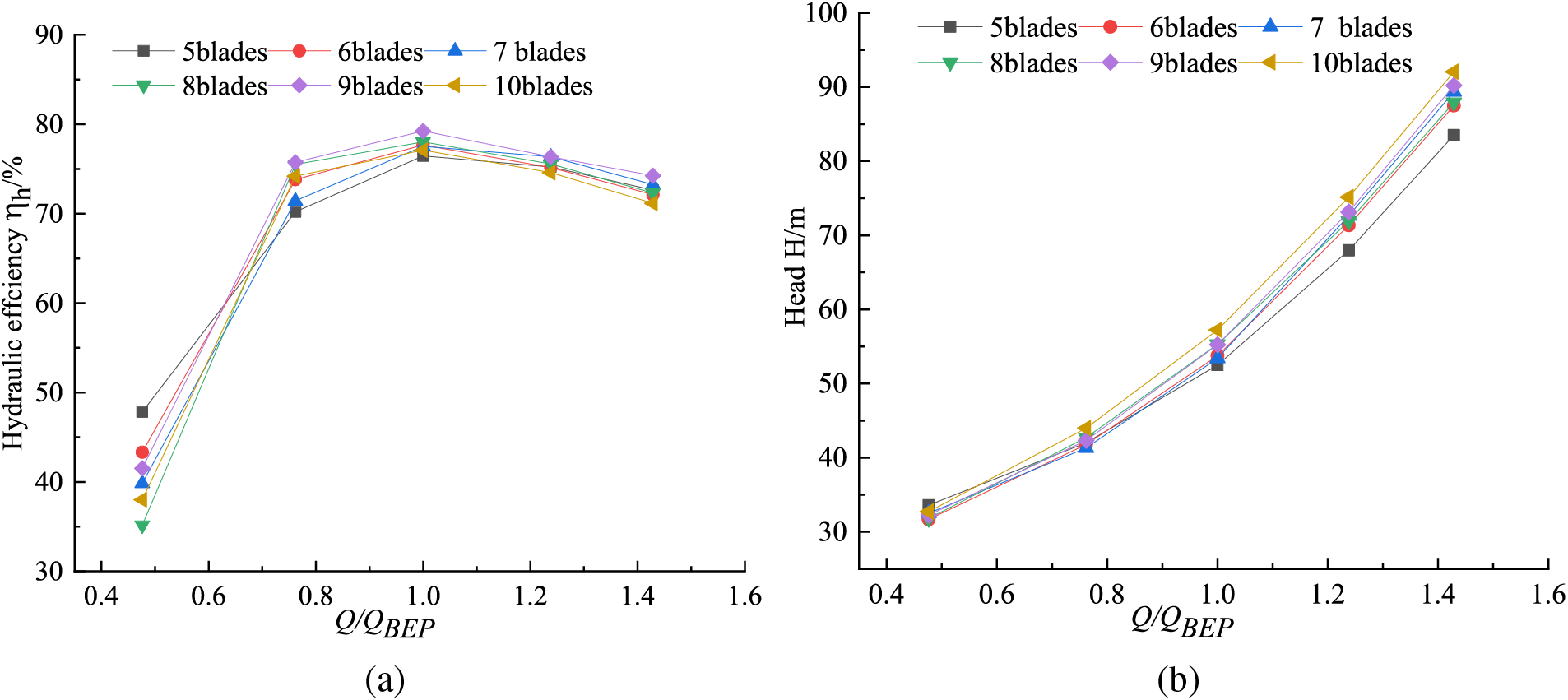
Figure 9: External characteristic curve with different number of blades. (a) Flow-Efficiency. (b) Flow-Head
From Fig. 9a can be seen that in the partial small flow conditions (Qt < 0.7QBEP), its hydraulic efficiency changes as follows: Z5 > Z6 > Z9 > Z7 > Z10 > Z8, Z5’s hydraulic efficiency is the largest, Z8’s hydraulic efficiency is the smallest, and Z8 hydraulic efficiency is smaller than Z5 by 20.5%. When the flow is Qt > 0.7QBEP, Z9’s hydraulic efficiency is the largest in each condition, the rest of the different blades number turbine hydraulic efficiency is different in size changes. When the flow rate 0.7QBEP < Qt < 1.5QBEP, the hydraulic efficiency of Z5 is the smallest, and when the flow rate Qt > 1.5QBEP, the hydraulic efficiency of Z10 is the smallest. The optimal working condition of these six different blades number turbine is the same, which is 1.0QBEP for all. In this working condition, the hydraulic efficiency of Z9 is 2.1% greater than that of the design blades Z6, which is 3.6% greater than Z5. The hydraulic efficiency gap of each blade number is large in the small flow working condition, while the gap is small in the large flow working condition.
From Fig. 9b can be seen, the head does not change largely with the increase of blades number in the small flow region, but the more the number of blades, the greater the head with the increase in flow, which is H10 > H9 > H8 > H7 > H6 > H5; when Qt > 0.6QBEP, the head of Z10 in each working condition is the largest; and when Qt > 1.0QBEP, the increase rate of each blade head are becoming larger, and Z10 has the largest increase rate. In the large flow area, the head among each blade is larger, and the head of Z10 is 5.2% larger than that of the design blade Z6, which is 10.25% larger than that of Z5.
4.3 Internal Static Pressure Distribution
To further investigate the differences in the performance of the hydraulic turbine with the variation of the number of blades, the paper analyzes the pressure clouds in the middle section of six impellers at the optimum operating condition (1.0QBEP) with different number of blades, as shown in Fig. 10.
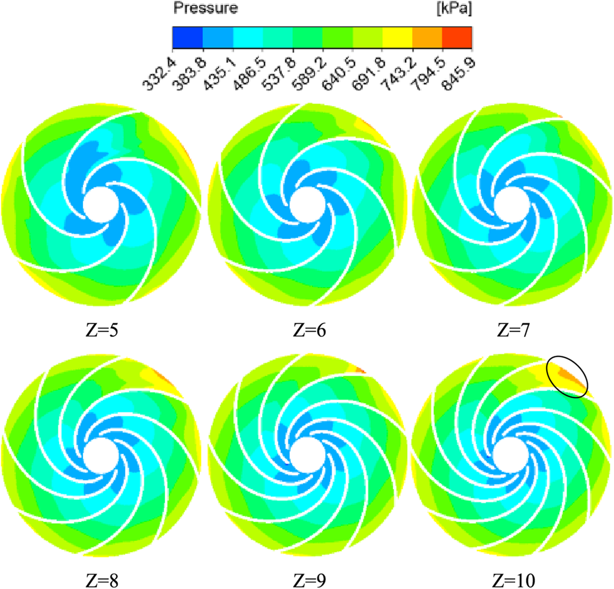
Figure 10: Pressure distribution in the middle section of impeller with different number of blades
From Fig. 10, it can be found that the pressure distribution in the middle section of the impeller with different blade numbers in the optimal working condition has an obvious gradient, the pressure gradually decreases from the impeller inlet to the impeller outlet, and there is a part of high pressure in the inlet of the volute and near the volute tongue area, and the inlet pressure of each impeller gradually increases with the increase of the blade number. The impeller has different blade numbers, and its low pressure area is also different, whose change law is: Z5 > Z6 > Z7 > Z8 > Z9 > Z10, that is the low pressure area gradually reduced with the increase in the number of blades impeller. The inlet pressure increases and the outlet pressure decreases which shows the head increases, that is the corresponding head gradually increased with the increase in the number of blades, which echoes with the results of the previous external characteristics analysis.
4.4 Transient Hydraulic Characterization
As Figs. 11 and 12 shown, the same defined functions is used for different blades number hydraulic turbines to monitor the transient head H and transient torque M, with time to obtain the time domain plots of the transition of transient head and torque to high and low flow rates, respectively [23,24].
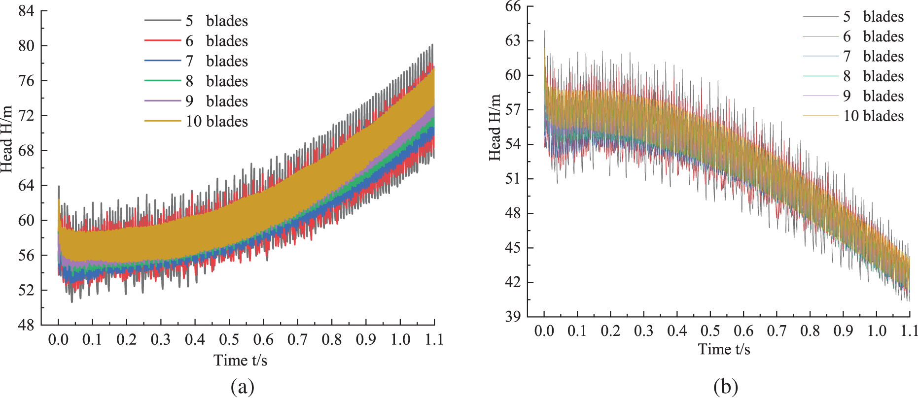
Figure 11: Transient head time domain diagram of variable flow process with different blade numbers. (a) Transition to large flow. (b) Transition to small flow
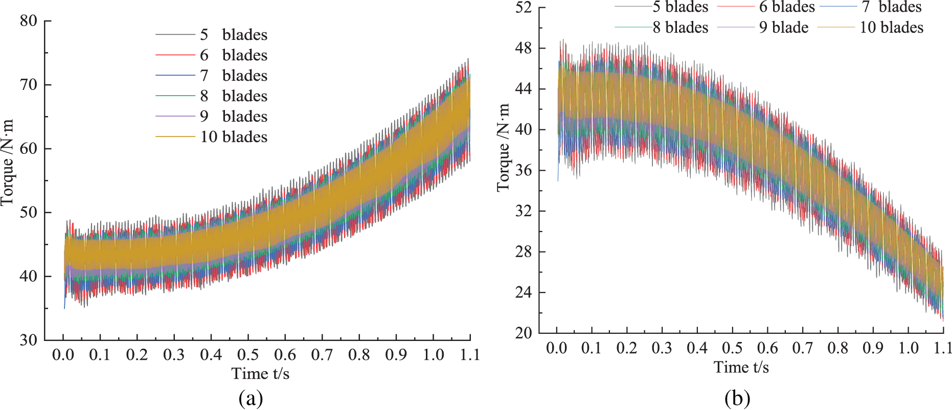
Figure 12: Transient torque time domain diagram of variable flow process with different blade. (a) Transition to large flow. (b) Transition to small flow
The presence of acceleration in hydraulic machinery during the transition process makes it necessary to use the generalized Euler equations when expressing the theoretical head. Zhang [25] derived an expression for the transient head in the transition process. Therefore, the theoretical head expression is:
where ΩJ, ΩM,—blade influence coefficient; the first item is the head at steady state; the last two items are the additional head during the transition process.
As can be seen from Fig. 11, during the transition process of variable flow rate of hydraulic turbine with different blade numbers, the transient head increases with time and the fluctuation range of head also gradually increases when it transitions to high flow; while the transient head gradually decreases with time and the fluctuation range also gradually decreases, when it transitions to low flow. In Fig. 11a, during the transition to a large flow, part of the transient head of the hydraulic turbine is increased, compared with the transient flow under stable conditions within 0~0.1 s, which is the additional head term in Formula (2). The result is consistent with the experimental results in the literature [26], and the additional head is caused by the acceleration of the fluid flow.
Similarly, the transition to a small flow rate in Fig. 11b is also due to the existence of additional head, which is caused by the deceleration of fluid flow. The transient head in the transition to high flow is significantly larger than the transient head in the transition to low flow.
In Fig. 11a, the increase in transient head gradually increases, and the largest fluctuation in transient head up and down is Z5, followed by Z6, and the smaller fluctuations is in Z9 and Z10, the head of Z10 is the largest, followed by Z9, which coincides with the previous analysis of the external characteristics, and the pressure distribution changes. In Fig. 11b, the transient head reduction amplitude gradually increases, and the head fluctuation rule is the same as high flow transition, that is, the more the number of blades in the transition process, the smaller the transient head fluctuation.
Fig. 12 shows the graph of transient torque with time for different blade numbers in the process of variable flow, the transient torque of the transition to large flow is obviously larger than that to small flow, the transient torque gradually increases with time in the transition to large flow, and its fluctuation range also gradually increases; while the transient torque gradually decreases with time in the transition to small flow, and its fluctuation range also gradually decreases. As shown in Fig. 12a, the transient torque increases gradually when it transitions to large flow, the biggest torque fluctuation of ups and downs is Z5, the smallest fluctuation is Z10, and the fluctuation range between Z9 and Z10 is very small. In Fig. 12b, the transient torque decreases gradually when it transitions to small flow, and the torque fluctuation rule is the same as large flow transition, that is, the more the number of blades in the transition process, the transient torque fluctuation is smaller.
According to Eq. (3), the hydraulic efficiency of the hydraulic turbine can be calculated, the formula is:
where M-torque, N·m; n-rotational speed, r/min; Q-volume flow rate, m3/s; H-head, m.
The transient hydraulic efficiency of different blade numbers hydraulic turbine is calculated according to Formula (3), in which there are three variables, transient torque M, transient head H, volume flow Q, torque and head are monitored by setting formula in the transition process numerical calculation, whose data is shown in Figs. 13 and 14. The flow changes adopt quadratic function type transition, and the mass flow changes throughout the transition process are obtained on the basis of Formula (1), then the mass flow is converted to volume flow and substituted into Formula (3), thus the transient hydraulic efficiency change of different blade numbers hydraulic turbine in the transition process of variable flow can be worked out, as shown in Fig. 13. It is found that the maximum value of hydraulic efficiency is within 0~0.1 s, and the fluctuation of hydraulic efficiency is also the largest in the time range. Fig. 13a shows the transient hydraulic efficiency of the transition to large flow with time by using different numbers of blades. After 0.1 s, the wave of hydraulic efficiency gradually decreases with the increase of time, the fluctuation range of hydraulic efficiency also gradually decreases, the largest fluctuation of hydraulic efficiency is Z5, and the smallest fluctuations are Z9 and Z10, but the transient hydraulic efficiency of Z9 is higher than that of Z10, which coincides with the highest efficiency of Z9 in steady state. Fig. 13b shows the transient hydraulic efficiency of the transition to small flow with time by using different number of blades. After 0.1 s, the wave peak of hydraulic efficiency gradually increased with the increase of time and the trough value of hydraulic efficiency gradually decreased, that is, the fluctuation range of hydraulic efficiency also gradually increased, and the transient hydraulic efficiency fluctuation changes of different number of blades is the same as large flow transition.
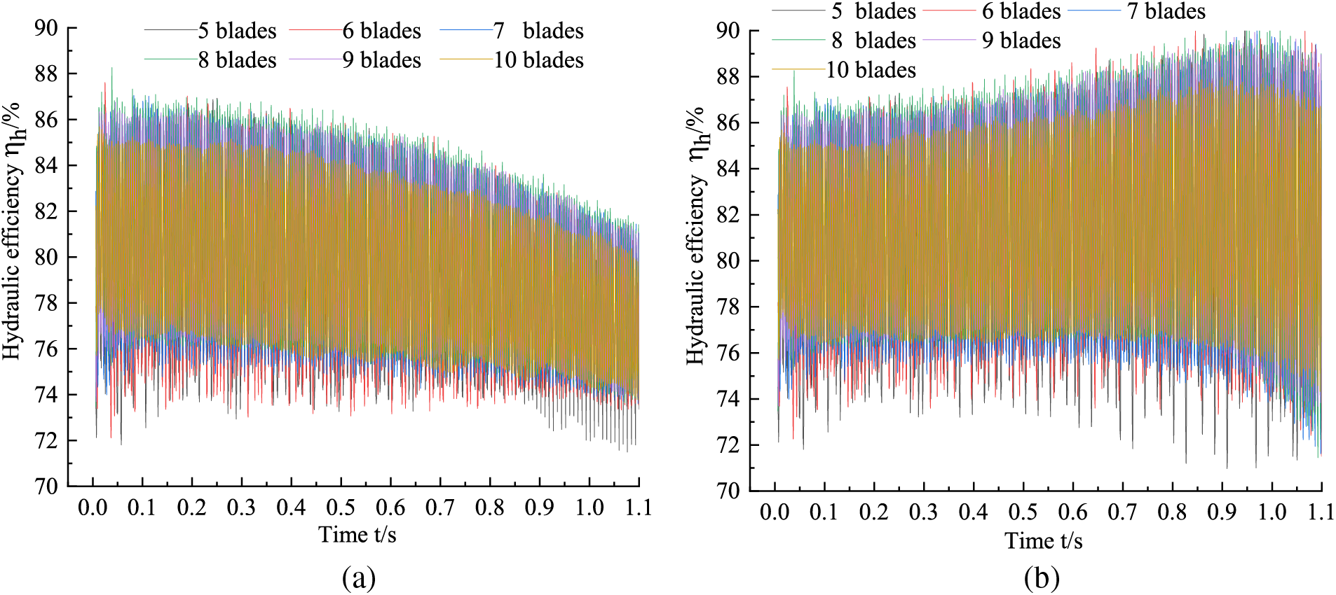
Figure 13: Transient hydraulic efficiency time domain diagram of variable flow process with different blade numbers. (a) Transition to large flow. (b) Transition to small flow
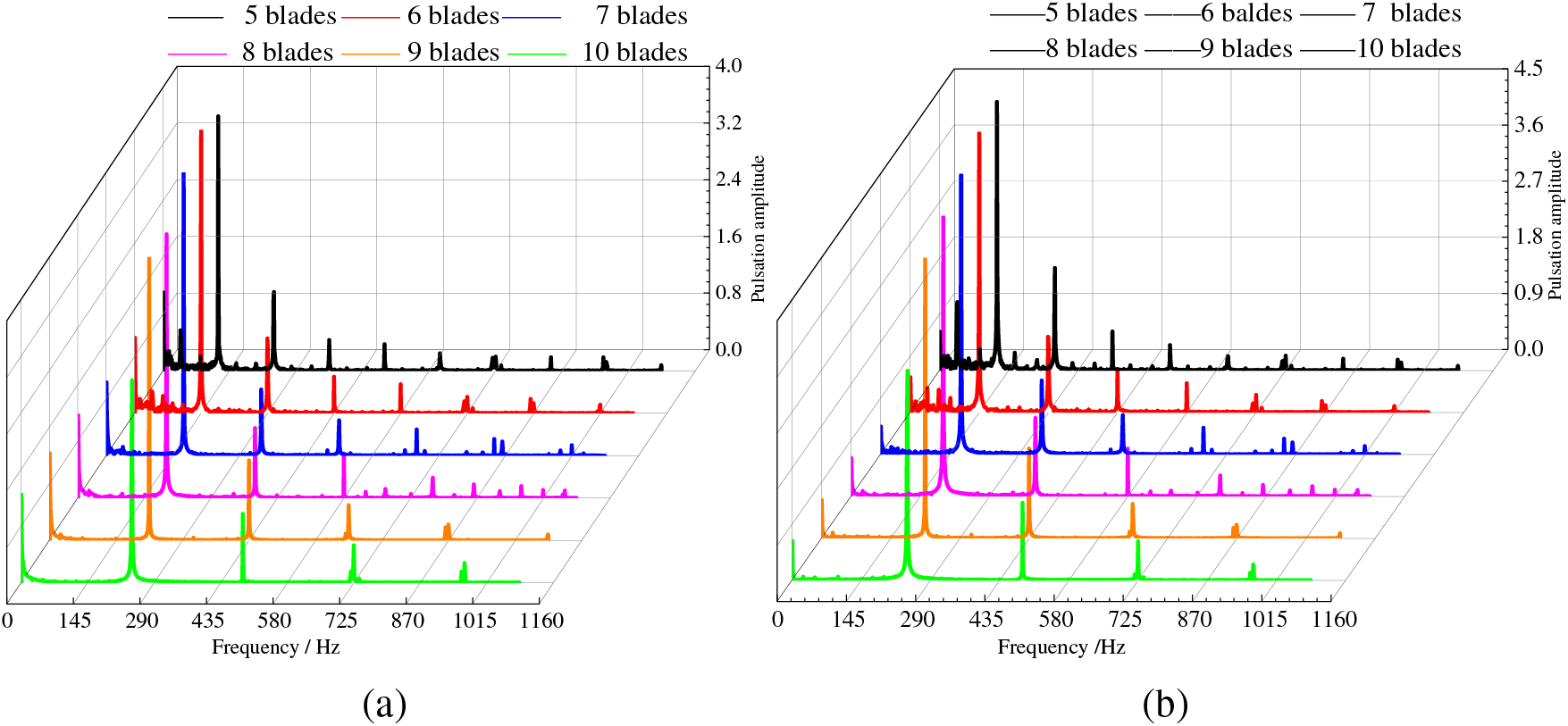
Figure 14: Frequency domain diagram of transient hydraulic efficiency in the process of variable flow rate with different blade numbers. (a) Transition to large flow. (b) Transition to small flow
In order to analyze the influence of different blades number on the hydraulic efficiency of hydraulic turbine during the transition process, the research selects hydraulic efficiency within 0~1.1 s for analysis, and adopts the fast Fourier transform (FFT) to obtain the frequency domain diagrams of transient hydraulic efficiency of different blades in the process of variable flow, as shown in Fig. 14, where the horizontal coordinate is the frequency f and the vertical coordinate is the pulsation amplitude of hydraulic efficiency. Fig. 14a,b represents the frequency domain diagrams of hydraulic efficiency for the transition to large flow and to small flow. It is found that the main frequency of the hydraulic efficiency of different blade numbers in these two transition processes is equal to the leaf frequency of the respective corresponding blades. The extracted pulsation amplitude at the main frequency of hydraulic efficiency in the transition process of variable flow, as shown in Table 3. The pulsation amplitude changes in the transition process to large flow: Z7 > Z9 > Z6 > Z8 > Z5 > Z10, with Z7 having the largest hydraulic efficiency pulsation amplitude and Z10 the smallest, Z7 in the main frequency pulsation amplitude is 54.78% larger than Z10, while Z7 in the main frequency pulsation amplitude is only 6.45%. The pulsation amplitude rule of different blades transitioning to small flow in the process is the same as that to large flow transition with Z7 the largest and Z10 the smallest, Z7 is 62.22% larger than Z10 in the main frequency pulsation amplitude, and the gap between Z7 and Z9 in the main frequency of the pulsation amplitude is only 4.46%.

4.5 Analysis of Pressure Pulsation
Pressure pulsation is mainly due to the hydraulic turbine in the operation process deviates from the optimal working condition to the transition of large flow or small flow in the rotor-stator interaction between the impeller and the volute, in addition to the hydraulic turbine internal unsteady flow impact.
To analyze the pressure pulsation change of different blades of hydraulic turbine in the variable flow transition process, a series of monitoring points are set in these 6 types of hydraulic turbine for non-constant monitoring. As shown in Fig. 15, monitoring points 1~5 are set on the volute, monitoring point 6 is set on the intersection of the impeller outlet and tail pipe inlet, the monitoring points of 6 different blades of the hydraulic turbine are set in the same position.
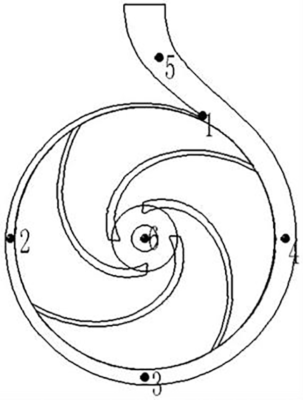
Figure 15: Monitoring point setting
To facilitate the following elaboration of pressure pulsations, dimensionless pressure coefficients are used here:
In the equation, p is the transient static pressure, Pa; pave is the average pressure, Pa; ρ is the medium density, kg/m3; u is the impeller inlet circumferential velocity, m/s. Which can be worked out by Formula (5).
In the equation, n is the impeller speed, r/min; D1 is the impeller inlet diameter, m.
The pressure at each monitoring point of the hydraulic turbine with different blade numbers is obtained by non-constant calculation, then the pressure values at each monitoring point is converted into a dimensionless pressure coefficient based on Eq. (4).
Fig. 16 shows the pressure coefficient change of each monitoring point of hydraulic turbine with time during the transition to large flow rate. The pressure coefficients of monitoring points 1~5 on the volute gradually increase with time, the pressure coefficient fluctuation range also gradually increases, the pressure coefficient values at monitoring point 1 and monitoring point 5 is relatively large, monitoring point 2, monitoring point 3 and monitoring point 4 are relatively small. Because the pressure pulsation is influenced not only by the dynamic and static interference, but also the influence of the volute tongue, and the monitoring points on the volute fluctuate with periodicity. The pressure coefficient of monitoring point 6 in the impeller outlet is the smallest and fluctuates without any periodicity, which means that it is less influenced by dynamic interference and volute tongue, and the pressure coefficient fluctuation range gradually decreases. The pressure coefficient wave peak is the largest at Z5, followed by Z6, and the smallest is Z10. For monitoring point 1, at about 1.0 s, the maximum value of Z5 pressure coefficient is 77.2% larger than that of Z10, the maximum value of Z6 pressure coefficient is 51.13% larger than Z10, the maximum value of Z7 pressure coefficient is 25.53% larger than Z10, the maximum value of Z8 pressure coefficient is 15.32% larger than Z10, and the maximum value of Z9 pressure coefficient is only 5.57% larger than Z10, so the difference between them is small, and the smaller fluctuation range of pressure coefficient are Z9 and Z10, but the fluctuation range of Z10 pressure coefficient increases firstly and then decreases in monitoring point 1.
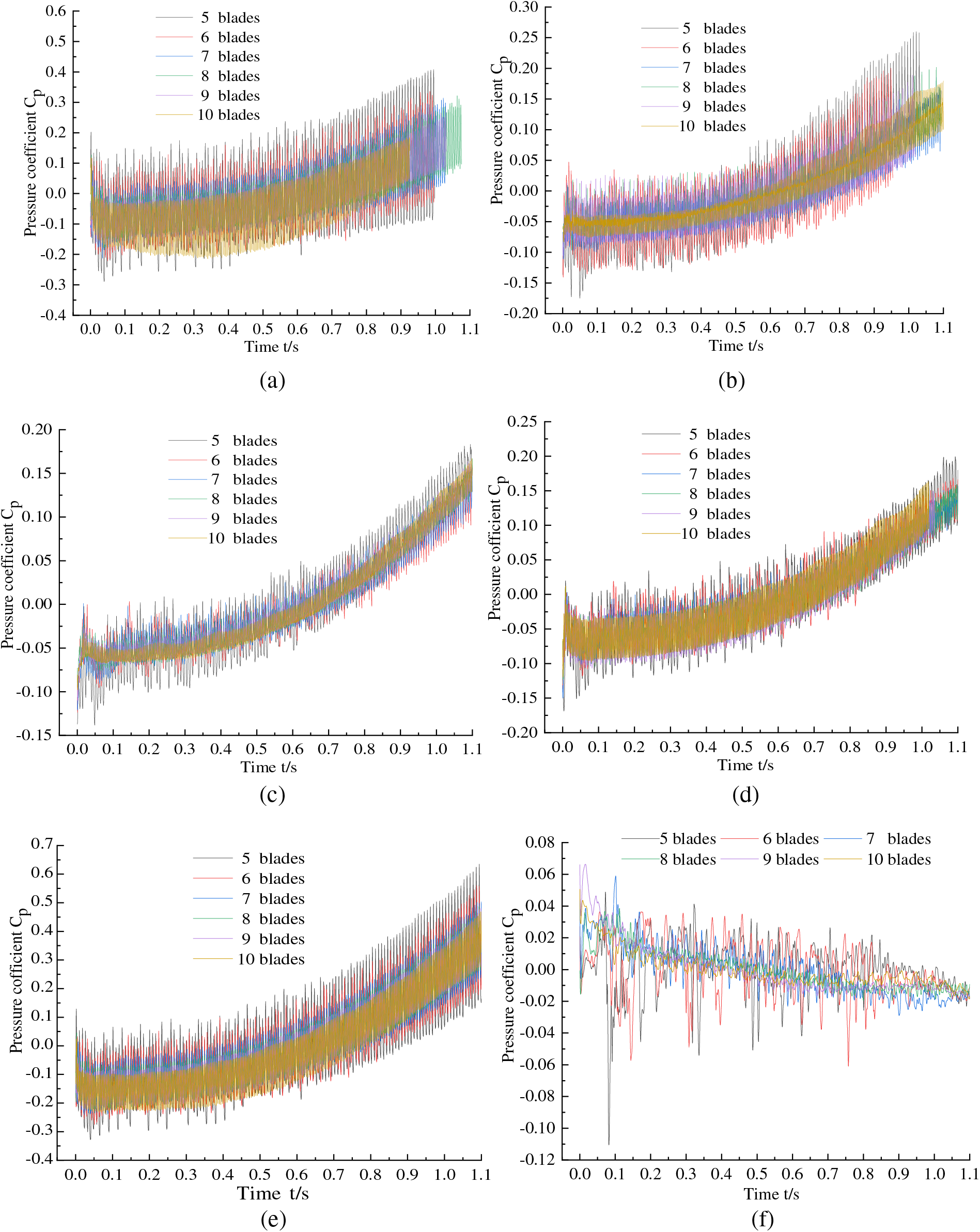
Figure 16: Time domain diagram of pressure pulsation at different monitoring points during the transition to large flow rate. (a) Monitoring point 1. (b) Monitoring point 2. (c) Monitoring point 3. (d) Monitoring point 4. (e) Monitoring point 5. (f) Monitoring point 6
Fig. 17 shows that in the process of transition to small flow, the pressure coefficient of each monitoring point of hydraulic turbine changes with time. The pressure coefficient points on the volute gradually decreases with the increase of time, and the pressure coefficient fluctuation range also gradually decrease. The pressure pulsation change rule of each monitoring point is the same as the transition to large flow, and the pressure coefficient value at monitoring point 1 and monitoring point 5 are larger compared to monitoring point 2, monitoring point 3 and monitoring point 4. The pressure coefficient of monitoring point 6 at the impeller outlet is the smallest, and the pressure pulsation is more chaotic without regularity.
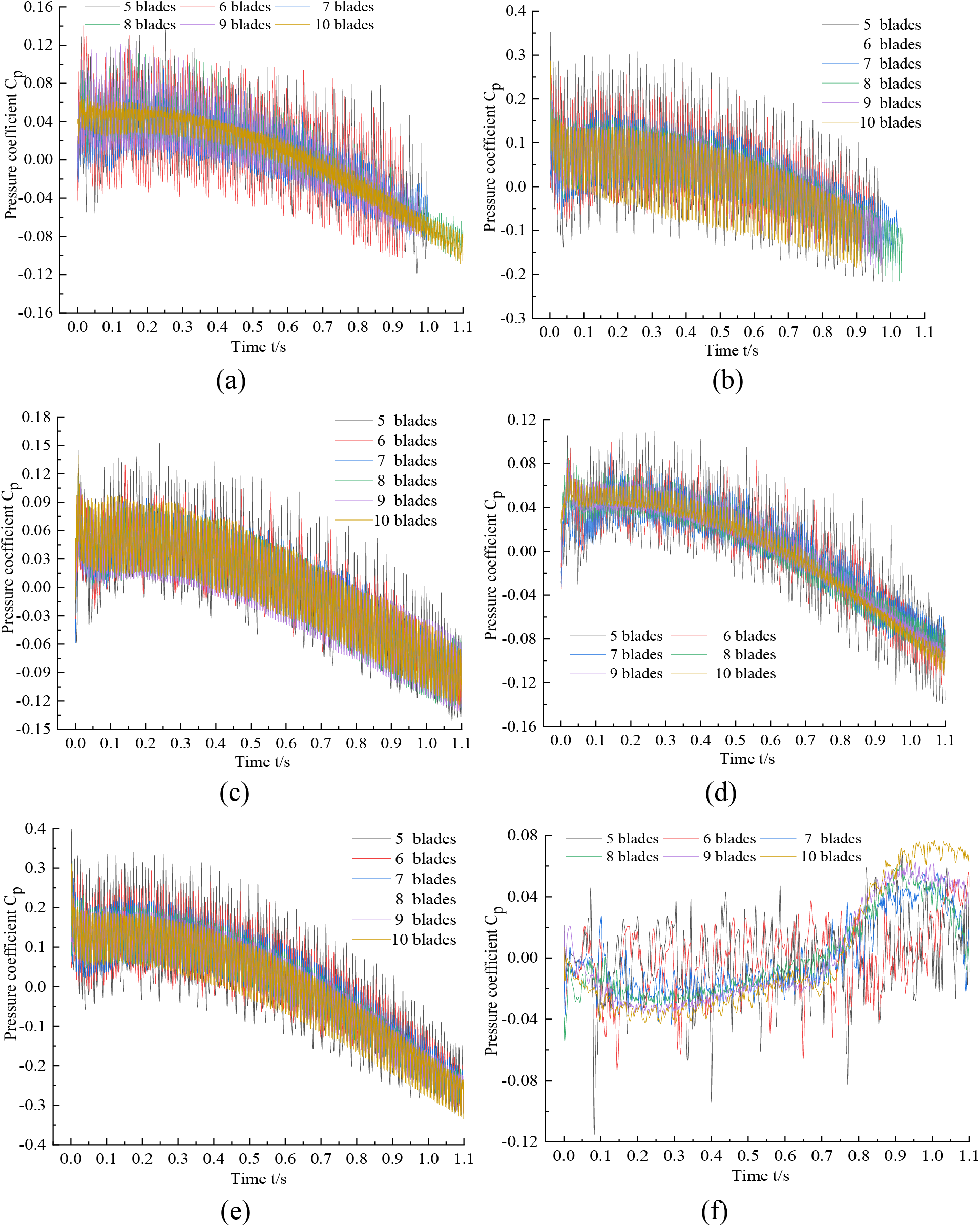
Figure 17: Time domain diagram of pressure pulsation at different monitoring points in the process of transition to small flow. (a) Monitoring point 1. (b) Monitoring point 2. (c) Monitoring point 3. (d) Monitoring point 4. (e) Monitoring point 5. (f) Monitoring point 6
The pressure coefficient change rule of each blade in the transition process to a small flow is similar with that to large flow transition. The more the number of blades, the smaller the pressure coefficient peak, and its pressure coefficient fluctuation range is also smaller. For monitoring point 1, at about 1.0 s, the maximum value of Z5 pressure coefficient is 75.32% larger than that of Z10, the maximum value of Z6 pressure coefficient is 50.65% larger than Z10, the maximum value of Z7 pressure coefficient is 16.47% larger than Z10, the maximum value of Z8 pressure coefficient is 10.76% larger than Z10, and the maximum value of Z9 pressure coefficient is only 4.71% larger than Z10, so the difference between them is small, and the smaller fluctuation range of pressure coefficient are Z9 and Z10, but the pressure coefficient fluctuation range of Z10 first increases then decreases in the monitoring point 1.
The paper designs six kinds of hydraulic turbines with different blade numbers and numerical simulation which is used to carry out a constant numerical study on the hydraulic turbine at the optimal condition, as well as a numerical study on the unsteady state characteristics during the transition process of variable flow.
(1) During the transition process of variable flow, with the increase of the number of blades, the range of transient hydraulic efficiency, head and torque fluctuation decreases step by step, with the increase of the number of blades, in which the fluctuation of Z9 is smaller; when transitioning to large flow, the pressure coefficient of each monitoring point increases with time, and when transitioning to small flow, the pressure coefficient of each monitoring point decreases with time.
(2) In the transition process, the dominant frequency of hydraulic efficiency pulsation is equal to the blade frequency, and the amplitude of hydraulic efficiency pulsation of Z7 is the largest, Z9 is the second, largest, and the difference between them is only 6.45% and 4.46%, and Z10 is the smallest, and the difference between them is 54.78% and 62.22%; with the increase in the number of blades, the range of pressure pulsation in the transition process decreases, and the coefficient of pulsation reaches the maximum in the volute tongue, and the range of fluctuation of Z9 is the smallest.
(3) After comprehensive comparison, Z9 is in the steady state with the highest efficiency of 79.24%. In the transition process of transient hydraulic efficiency, the pressure pulsation fluctuation range is small, so the hydraulic turbine blade number of Z9 is optimal for the pump.
Acknowledgement: The authors would like to thank the members of the School of Energy and Power Engineering, Lanzhou University of Technology.
Funding Statement: The authors would like to thank the support of the Gansu Provincial Department of Education College Teachers’ Innovation Fund Project (2024A-021), Colleges and Universities Industrial Support Program Projects of Gansu Province (Grant No. 2020C-20) and Key Laboratory of Fluid and Power Machinery, Ministry of Education, Xihua University (Grant No. szjj2019-016, LTDL2020-007).
Author Contributions: Study conception and design: Fengxia Shi, Guangbiao Zhao; data collection: Guangbiao Zhao, Yucai Tang, Dedong Ma, Xiangyun Shi; analysis and interpretation of results: Guangbiao Zhao, Yucai Tang; draft manuscript preparation: Guangbiao Zhao. All authors reviewed the results and approved the final version of the manuscript.
Availability of Data and Materials: All the data used in the study are included in the manuscript.
Ethics Approval: Not applicable.
Conflicts of Interest: The authors declare that they have no conflicts of interest to report regarding the present study.
References
1. Chen XP, Zhang ZG, Huang JM, Zhou XJ, Zhu ZC. Numerical investigation on energy change field in a centrifugal pump as turbine under different flow rates. Renew Energ. 2024;230. doi:10.1016/j.renene.2024.120804. [Google Scholar] [CrossRef]
2. Angelo A, Demetrio AZ, Angelo N, Santo ZM. Potential energy exploitation in collective irrigation systems using pumps as turbines: a case study in Calabria (Southern Italy). J Clean Prod. 2020;257. [Google Scholar]
3. Paolo C, Maria CV. Application of a hydraulic gas bladder suppressor for pressure ripple reduction in gear pumps. J Phys: Conf Series. 2023;2648:012050. doi:10.1088/1742-6596/2648/1/012050. [Google Scholar] [CrossRef]
4. Li ZG, Xu LX, Wang D, Li DY, Wang X. Simulation analysis of energy characteristics of flow field in the transition process of pump condition outage of pump-turbine. Renew Energ. 2023;219(1):1–12. doi:10.1016/j.renene.2023.119480. [Google Scholar] [CrossRef]
5. Svarstad FM, Nielsen KT. Pressure pulsations during a fast transition from pump to turbine mode of operation in laboratory and field experiment. IOP Conf Ser: Earth Environ Sci. 2019;240(8):1–11. doi:10.1088/1755-1315/240/8/082006. [Google Scholar] [CrossRef]
6. Riedelbauch S, Stens C. Pump to turbine transient for a pump-turbine in a model test circuit and a real size power plant. IOP Conf Ser: Earth Environ Sci. 2019;240(7):1–13. doi:10.1088/1755-1315/240/7/072039. [Google Scholar] [CrossRef]
7. Teiichi T, Naoto T. Transient characteristics of a centrifugal pump at rapid startup. IOP Conf Ser: Earth Environ Sci. 2019;240(5):1–12. doi:10.1088/1755-1315/240/5/052016. [Google Scholar] [CrossRef]
8. Si QR, Xin X, Wu KP, Deng FJ, Yuan SQ. Transient characteristics of the hydraulic transition process of emergency water supply multi-stage pump with unexpected shutdown. Trans Chin Soc Agric Eng. 2024;40(4):72–81 (In Chinese). doi:10.11975/j.issn.1002-6819.202308219. [Google Scholar] [CrossRef]
9. Shi GT, Liu XB, Wei WJ. Internal pressure fluctuation characteristics of hydraulic turbine with guide vane. J Drain Irrig Mech Eng. 2017;35(1):6–12+55. [Google Scholar]
10. Minakov AV, Platonov DV, Sentyabov AV. Numerical simulation of swirling flow modes in a model of a hydraulic turbine and a draft tube. Thermophys Aeromechan. 2023;30(1):37–42. doi:10.1134/S0869864323010055. [Google Scholar] [CrossRef]
11. Wack J, Grubel M, Conrad P, Von LF, Jester ZR. Numerical investigation of the impact of cavitation on the pressure fluctuations in a Francis turbine at deep part load conditions. IOP Conf Ser: Earth Environ Sci. 2022;1079(1):012044. doi:10.1088/1755-1315/1079/1/012044. [Google Scholar] [CrossRef]
12. Ni D, Wang FF, Gao B, Zhang Y, Zhang N. Study on pressure pulsation characteristics of a centrifugal pump with split half staggered impeller. J Eng Thermophys. 2023;44(6):1565–71 (In Chinese). [Google Scholar]
13. Al-Obaidi AR, Alhamid J, Khalaf H. Unsteady behaviour and plane blade angle configurations’ effects on pressure fluctuations and internal flow analysis in axial flow pumps. Alex Eng J. 2024;99(4):83–107. doi:10.1016/j.aej.2024.04.048. [Google Scholar] [CrossRef]
14. Akihito U, Tomoki T, Daisuke S, Miyagawa K. Effect of the number of blades on diffuser unsteady loss of centrifugal pump. J Phys: Conf Ser. 2022;2217(1):012052. doi:10.1088/1742-6596/2217/1/012052. [Google Scholar] [CrossRef]
15. Li J, Wei QS. Influence of different guide blade number on internal flow field of submersible pump under unsettled operating conditions. Agric Eng. 2022;12(10):101–6. [Google Scholar]
16. Li YB, Guo DS, Fan ZJ, Du J. Effects of different blade numbers on radial exciting force of lobe pump rotor. Int J Fluid Machinery Syst. 2020;13(2):281–91. doi:10.5293/IJFMS.2020.13.2.281. [Google Scholar] [CrossRef]
17. Gamal RH, Magdy AB, Khalil YK, Mohamed SG. Effect of impeller blades number on the performance of a centrifugal pump. Alex Eng J. 2019;58(1):39–48. doi:10.1016/j.aej.2019.02.004. [Google Scholar] [CrossRef]
18. Shi FX, Ma DD, Zhao WY, Peng HT, Lian YS. Effect of different blade numbers on the radial force of pump as turbine in transient process. Int J Fluid Machin Syst. 2021;14(2):142–9. doi:10.5293/IJFMS.2021.14.2.142. [Google Scholar] [CrossRef]
19. Shi FX, Tang YC, Ma DD, Shi XY, Zhao GB. Influence of different transition modes on the performances of a hydraulic turbine. Fluid Dyn Mater Process. 2023;19(10):2481–97. doi:10.32604/fdmp.2023.028416. [Google Scholar] [CrossRef]
20. Wang XL, Yuan SQ, Zhu RS, Fu Q, Wang JG. Effect of blade number on radial force of nuclear main pump under transient conditions. J Vib Shock. 2014;33(21):51–9 (In Chinese). [Google Scholar]
21. Wang XH, Yang JH, Guo YL, Xia ZT, Miao SC. Velocity slip mechanism of reverse pump hydraulic turbine. J Mech Eng. 2018;54(24):189–96. doi:10.3901/JME.2018.24.189. [Google Scholar] [CrossRef]
22. Wang FJ. Flow analysis method of pump and pumping station. China: China Water Res Hydropow Press; 2020. [Google Scholar]
23. Zhou SQ, Kong FY, Wang ZQ, Yi CL, Zhang Y. Numerical simulation of low specific speed centrifugal pump performance based on structured grid. J Agric Mach. 2011;42(7):66–9 (In Chinese). [Google Scholar]
24. Zhao BJ, Yuan SQ, Chen HL. Unsteady flow characteristics in double channel pump based on sliding grid. J Agric Eng. 2009;25(6):115–9+318 (In Chinese). [Google Scholar]
25. Zhang YL. Transient internal and external flow characteristics of centrifugal pump during start-up. China: Zhejiang University; 2013. [Google Scholar]
26. Wang LQ, Wu DZ. Experimental study on transient characteristics of mixed flow pump during rapid load change. General Mach. 2003;2:65–8 (In Chinese). [Google Scholar]
Cite This Article
 Copyright © 2024 The Author(s). Published by Tech Science Press.
This work is licensed under a Creative Commons Attribution 4.0 International License , which permits unrestricted use, distribution, and reproduction in any medium, provided the original work is properly cited.


 Submit a Paper
 Propose a Special lssue
 View Full Text
 Download PDF
 Downloads
 Citation Tools