 Open Access
ARTICLE
Experimental Study of Thermal Convection and Heat Transfer in Rotating Horizontal Annulus
Laboratory of Vibrational Hydromechanics, Perm State Humanitarian Pedagogical University, Perm, 614990, Russia
* Corresponding Author: Alexei Vjatkin. Email:
(This article belongs to the Special Issue: Advanced Problems in Fluid Mechanics)
Fluid Dynamics & Materials Processing 2024, 20(11), 2475-2488. https://doi.org/10.32604/fdmp.2024.052377
Received 31 March 2024; Accepted 24 June 2024; Issue published 28 October 2024
Abstract
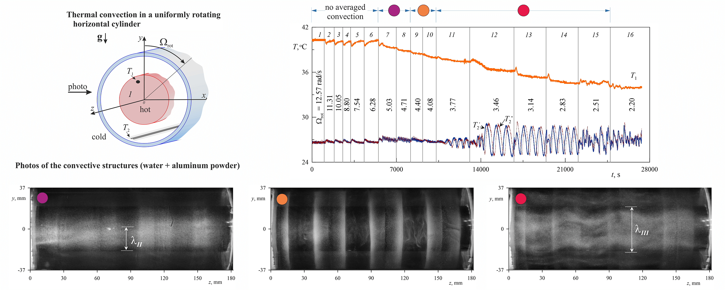
A genuine technological issue–the thermal convection of liquid in a rotating cavity–is investigated experimentally. The experiments are conducted within a horizontal annulus with isothermal boundaries. The inner boundary of the annulus has a higher temperature, thus exerting a stabilising influence on the system. It is shown that when the layer rotation velocity diminishes, two-dimensional azimuthally periodic convective rolls, rotating together with the cavity, emerge in a threshold manner. The development of convection is accompanied by a significant intensification of heat transfer through the layer. It is shown that the averaged thermal convection excitation in the form of a system of two-dimensional rolls occurs against the background of oscillations of a non-isothermal fluid in the cavity reference frame caused by the gravity field. The excitation threshold and the structure of convective rolls are consistent with the results of the earlier theoretical studies by the authors performed using the equations of “vibrational” convection obtained by the averaging method. Furthermore, the experiments have revealed a new type of averaged flow in the form of a spatially periodic system of toroidal vortices. It is shown that a steady streaming, excited by the inertial oscillations of the fluid, is responsible for the generation of the toroidal vortices. These flows develop in a non-threshold manner and are most clearly manifested in a case of resonant excitation of one of the inertial modes.Graphic Abstract
Keywords
Nomenclature
| | Amplitude of the oscillating force field modulation, m s−2 |
| | The amplitude of vibrations, m |
| | Mass concentration of the aqueous solution of glycerol, % |
| | Outer diameter of the layer, m |
| | Inner diameter of the layer, m |
| | Gravity acceleration, m s−2 |
| | Thickness of the layer, m |
| | Length of the layer, m |
| | Wave number |
| | Nusselt number |
| | Prandtl number |
| | Heat release capacity, W |
| | Average radius of the cylindrical layer, m |
| | Centrifugal Rayleigh number |
| | Gravitational Rayleigh number |
| | Vibrational parameter |
| | Temperature of the inner boundary of the layer, °C |
| | Temperature of the outer boundary of the layer, °C |
| | Temperature in the water jacket, °C |
| | Taylor number |
| | Thermal expansion coefficient, К−1 |
| | Thermal diffusivity, m2 sc1 |
| | Angular distance between temperature sensors, deg |
| | Kinematical viscosity, m2 s−1 |
| | Temperature difference at the layer boundaries in the absence of convection, °C |
| | Temperature difference at the layer boundaries, °C |
| | Relative thickness |
| | Period of temperature oscillations |
| | Angular velocity of rotation, rad s−1 |
| | The radian frequency of vibrations, rad s−1 |
| | The angular velocity of the drift, rad s−1 |
| | Dimensionless rotation velocity |
Thermal convection in rotating systems is a fundamental problem of current interest and importance for various technological processes [1–4]. One of the examples is thermal convection in rotating stars and planets [5–7]. Fluid oscillations can have a strong effect on convection. In the case of stars and planets, oscillations of liquid cores and atmospheres can be caused by various reasons. These could be tidal oscillations caused by the gravitational interaction with satellites or inertial oscillations associated with the action of the Coriolis force [8,9]; oscillations can also be excited by vibrations of solids (cores) inside the rotating liquid [10] and uneven rotation of the shell [11,12]. It is known that high-frequency oscillations of a non-isothermal fluid generate an averaged mass force that can both suppress thermal convection and cause it. This independent mechanism of averaged thermal convection is usually called a “thermovibrational” one [13].
In a uniform oscillating force field
Here
Different aspects of “Vibrational thermal convection” is being intensively researched nowadays [14–18] both experimentally and theoretically. In technological terms, vibrations are an effective way of controlling various fluid processes. A horizontal fluid layer with a vertical temperature gradient under the action of longitudinal vibrations of finite frequency is considered in [14]. The simulation results showed that the effect of vibration on the stability threshold is complex: vibration can both stabilise and destabilise the ground state depending on the values of the parameters. The effect of vibration on silicon melt in the crucible to further control the crystallisation process is theoretically and numerically studied in [15]. In [16], a model of vibrational convection in a heterogeneous mixture of two liquids separated by diffusion boundaries is obtained. Another direction of research is related to the manifestation of thermovibrational convection in microgravity conditions. Thus, in the case when vibration and temperature gradient are parallel, a series of new convection modes are found for the cubic cavity geometry [17]. The researches are not limited to single-phase systems. In [18], the regularities of clustering of non-isodense particles of finite mass and finite size induced by turbulent thermovibrational flow are presented. A large number of studies devoted to the manifestation of thermovibrational convection in various technological applications (multiphase media, porous media, liquid mixtures, microgravity) indicate the relevance of this scientific direction.
Averaged thermal convection in cavities rotating around a horizontal axis represents a special class of problems in which the “thermovibrational mechanism” is manifested. In this case, there is no vibration effect on the cavity, and the role of the periodic forcing is played by gravity oscillating in the cavity reference frame with a frequency equal to
It is clear that in (2) the gravity acceleration
The purpose of this work is to experimentally study the features of averaged thermal convection in a uniformly rotating horizontal cylinder of an average thickness
2 Experimental Setup and Techniques
The paper examines thermal convection in a rotating cylindrical layer with boundaries of different temperatures. The working cavity is a system of coaxially arranged cylinders (Fig. 1a): 1–internal aluminum cylinder, 2 and 3–transparent plexiglass pipes of different diameters. The cylinders 1–3 are sealed in flanges that define a coaxial arrangement and solid rotation around the horizontal axis. The working layer is enclosed between an aluminum heat exchanger 1 and the pipe 2. Parameters of the formed gap are the inner diameter
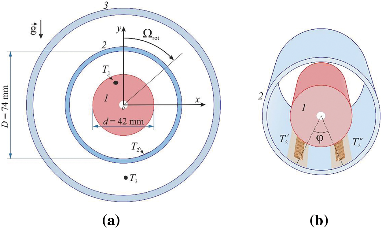
Figure 1: Working cavity scheme (a) and temperature sensors location scheme (b)
The inner boundary of the layer is heated by an electric wire heater installed in the centre of the aluminium heat exchanger along its entire length. A coolant of a constant temperature of 20°C is pumped between pipes 2 and 3 (referred to as the “jacket”) to ensure the cooling of the layer through the outer cylindrical boundary. A powerful jet thermostat LIOP LT-400 is used to circulate the coolant. The large volume of pumped liquid allows to ensure the constancy of its temperature regardless of the realised mode of convection in the layer. The temperature sensors are copper resistance thermometers. The temperatures
The sensors that measure the temperature
The experimental procedure is as follows. At the beginning of the experiment, the power on the electric heater is set. Using a jet thermostat LIOP LT-400, cooling water at a temperature of 20°C is supplied into the “jacket”. The working cavity is rotated at a relatively high angular velocity
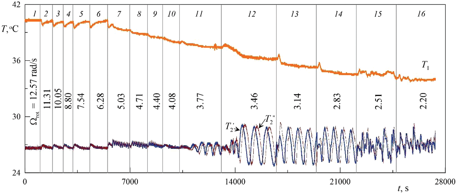
Figure 2: Typical view of the temperature recording during stepwise reduction angular velocity of rotation
After the experiment, the average temperature values
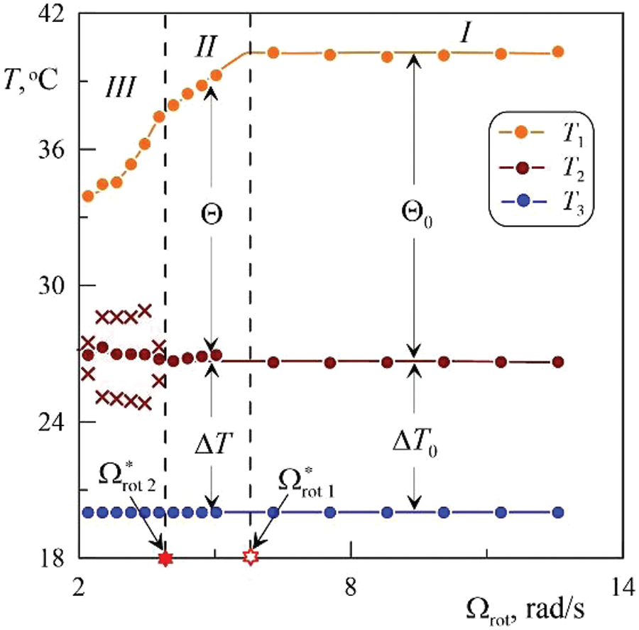
Figure 3: Temperatures
As already noted, the power
Temperature measurements. The experiments have shown that the sequence of changes in the convective modes with a decreased cavity angular velocity of rotation depends on the power of heat release in the inner cylinder, which is characterized by the temperature difference between the layer boundaries
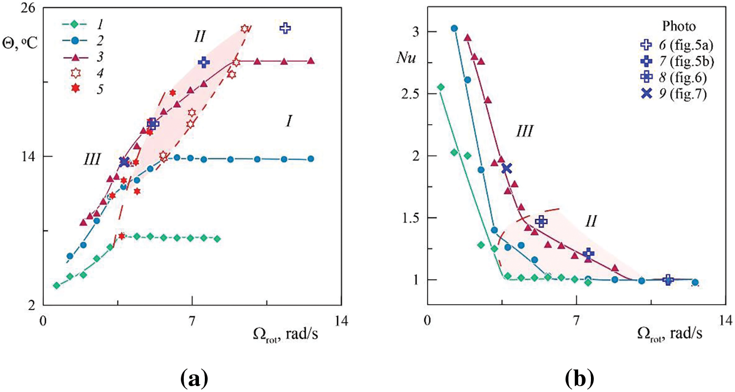
Figure 4: Dependence of the temperature difference
For small temperature changes (Fig. 4a, curve 1) disruption of the equilibrium of a non-isothermal fluid in a centrifugal field with a decrease of the angular velocity of rotation occurs according to a different scenario. It is observed on the border of areas I and III (Fig. 4, dashed line, points 5) and is accompanied by the appearance of regular temperature fluctuations recorded by a sensor at the outer boundary of the layer. As will be shown below, the dashed line (points 5) corresponds to the threshold of vibrational thermal convection excitation, accompanied by the appearance of large-scale 2D vortices, the slow azimuthal drift of which leads to the temperature fluctuations at the outer boundary of the layer.
At large temperature differences
With an increase in the equilibrium temperature difference between the layer boundaries
Let us dwell on heat transfer through the layer during rotation. To do this, introduce the Nusselt number, which characterizes the ratio of heat transport through the layer to conductive heat transport at the same power of heat release,
At rapid rotation
The heat transfer curves have a characteristic form for each convective mode: with a decrease in the rotation velocity, heat transport in the area II increases less intensively than that in the area III. The break in the heat transport curves corresponds to the threshold of the convective regimes change (border of areas II and III).
Photo registration. Photo recording is carried out using aluminum powder added to a liquid using a small amount of surfactant. The powder, which has a density higher than the density of the liquid, is distributed under the centrifugal force of inertia on the inner wall of the cavity (the outer boundary of the working layer). The surfactant is necessary to ensure the mobility of the powder and prevent it from sticking to the cavity boundaries. The photo in Fig. 5a shows the distribution of powder on the outer boundary of the working layer. In the central part of the frame, one can see an aluminum heat exchanger covered with black film for better visualization. For the observer (the camera is immovable in the laboratory reference frame), the lower boundary of the layer rises.
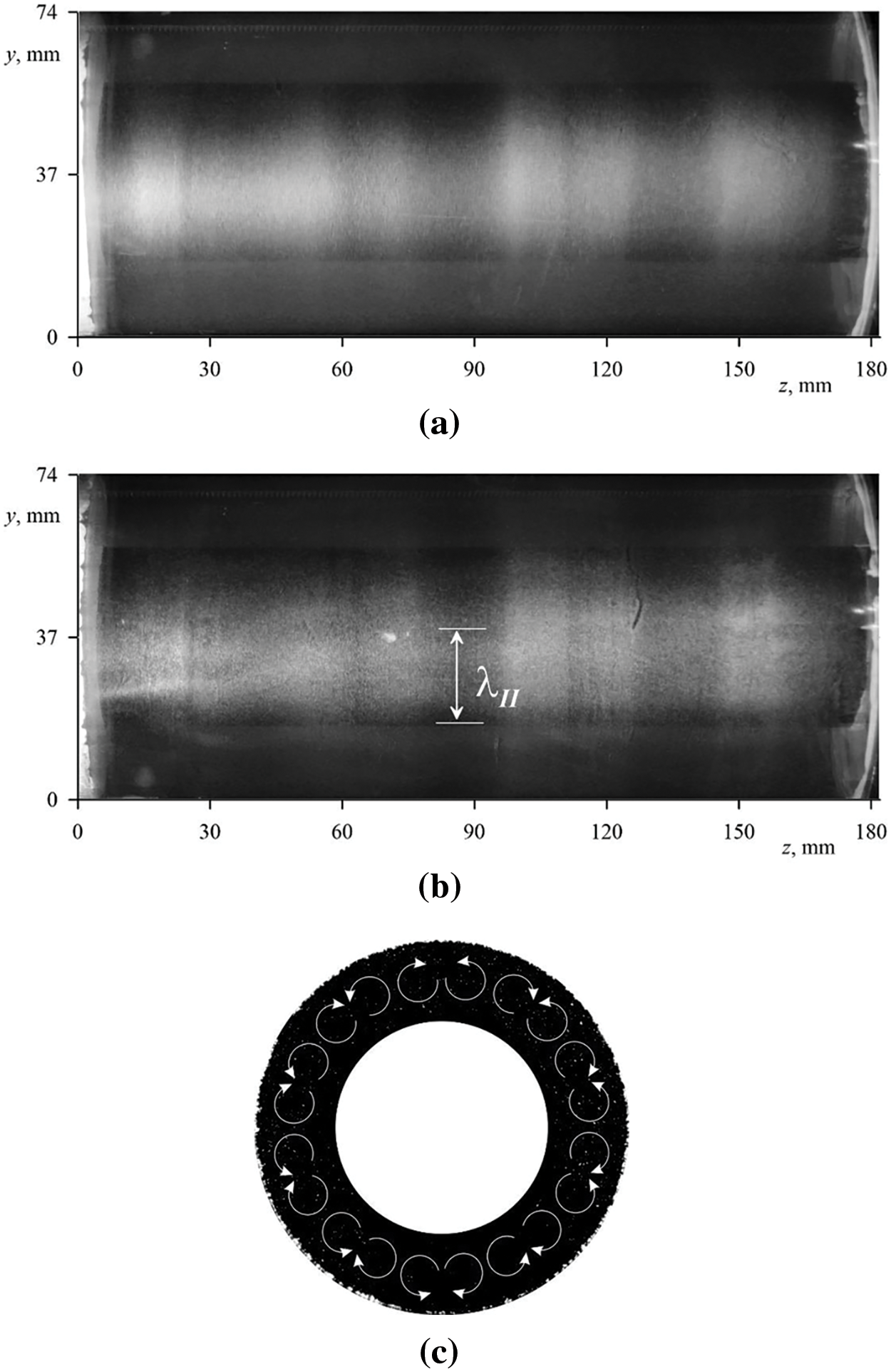
Figure 5: Photos of the convective structures (a, b) and the flow pattern (c). The experimental conditions correspond to the points 6 and 7 in Fig. 4: (a)
At rapid rotation, heavy particles of the visualizer are distributed on the outer wall of the layer, while remaining mobile. The powder is concentrated in the form of rings (light stripes in Fig. 5a), periodically located along the cavity axis. In the center of each ring, there is a dark stripe where there is practically no aluminum powder, and the contours of the rings are blurred. The rings of aluminum powder indicate the existence of a system of weak toroidal vortices periodically located along the layer. It should be noted that the existence of toroidal vortices, arising in a non-threshold way, in this range of experimental parameters has virtually no effect on heat transfer–photo in Fig. 5a corresponds to the thermal conductivity regime (area I in Fig. 4a).
The first heat transport crisis (the border of areas I and II in Fig. 4a) is accompanied by the appearance of the longitudinal convective rolls located along the axis of rotation (Fig. 5b). Adjacent rolls rotate in concert in opposite directions. These longitudinal convective structures are poorly expressed in the photo due to the fact that the visualizer is heavy aluminum powder, most of which is concentrated on the wall, while the rolls are localized in the bulk of the layer. The longitudinal rolls wavelength
With further decrease in the angular velocity of rotation near the transition of modes II and III the position of the rings changes (Fig. 6a), and the edges of the rings become more pronounced. Two-dimensional convective rolls do not manifest themselves, while three-dimensional toroidal structures provide a relatively large heat transport. According to the observations, we can conclude that the intensity of toroidal vortexes grows with a decrease in rotation rate, which results in the blurring of relatively weak longitudinal rolls, near the threshold curve III. The scheme of the toroidal vortices in the axial cross-section of the upper part of the layer is shown in Fig. 6b. The absence of temperature fluctuations recorded by a longitudinal integral sensor at the outer boundary of the layer proves that the toroidal vortices do not have azimuthal periodicity.
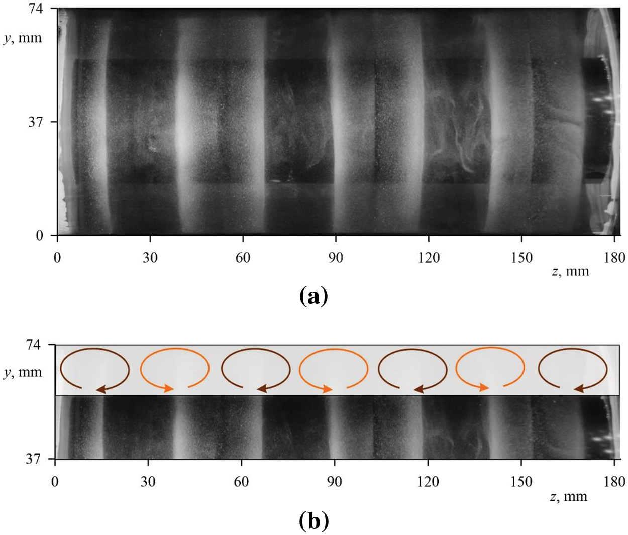
Figure 6: Photographs of the aluminum powder distribution on the cavity wall (a) and the schema of the steady flows in the layer (b). The experimental conditions correspond to the mark 8 in Fig. 4:
With a further decrease in the angular velocity of rotation there again observed a threshold manner appearance of the longitudinal rolls in the layer (Fig. 7). The wavelength
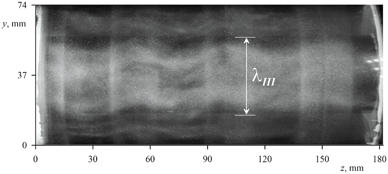
Figure 7: Photos of the convective structures. The experimental conditions correspond to the mark 9 in Fig. 4:
Drift of the convective structures. Earlier, in it was found that the longitudinal rolls in this range of experimental parameters are excited due to the dominant action of the thermovibrational mechanism. In experiments with thin layers, the drift of large-scale two-dimensional convective rolls was discovered and described in [23]. To study the phenomenon of the supercritical dynamics of convective flows in the form of two-dimensional rolls, a technique was proposed using several longitudinal integral temperature sensors located at a given distance from each other. The drift of the liquid layer is recorded by the sensors in the form of temperature fluctuations shifted in time (Fig. 8). The information about the time shift and the oscillation period allows one to calculate the drift velocity and the convective structures wavelength.
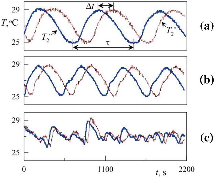
Figure 8: Temperature fluctuations recorded by two temperature sensors spaced apart in azimuth at the outer boundary of the layer (corresponding to steps 11 (a), 13 (b) and 15 (c) in Fig. 2)
Let us calculate the drift velocity and wavelength from the temperature fluctuations recording in Fig. 8a. Temperature fluctuation shift
Thermal convection in a thin cylindrical layer located horizontally and uniformly rotating around a horizontal axis was experimentally studied in [22,23]. It was shown that in the case of the layer heated from the internal boundary, the convection has a thermal vibrational nature and manifests itself in the threshold development of the rolls elongated along the axis of rotation. The control parameters are the centrifugal Rayleigh number
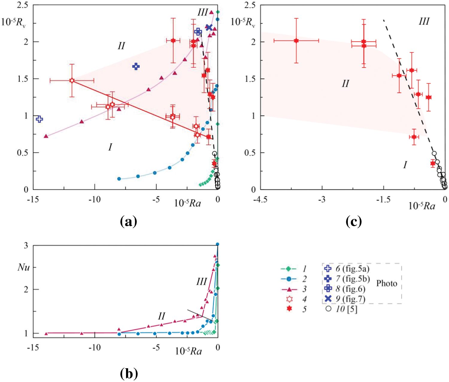
Figure 9: Experimental results on the plane of control parameters: vibration parameter
With decreasing the centrifugal Rayleigh number
Points 5 in Fig. 9 marks the excitation threshold of thermal vibrational convection, manifested in the form of longitudinal rolls of large transverse size (Fig. 7). The dashed line shows the theoretical threshold curve obtained in [22]. Threshold points 10 were obtained in the experiments with thin layers in the same formulation of the problem [23]. Fig. 9c separately shows the excitation thresholds of thermovibrational convection with an enlarged scale along the horizontal axis. In [23], the analysis of experimental and theoretical research results shows that one more important parameter describing thermovibrational convection is the dimensionless rotation velocity
The structure of convective flows in a rotating horizontal cylindrical layer of moderate thickness
Regardless of the toroidal structures, two threshold transitions were discovered as the angular velocity of rotation decreased. The first of the transitions manifests itself in a relatively small but threshold, intensification of heat transport. The convective structure observed in the layer was a system of azimuthally periodic two-dimensional convective rolls with the size consistent with the thickness of the layer. The nature and the generation mechanism of these rolls, which were observed simultaneously with toroidal structures, are not fully understood and need to be studied.
The second threshold transition and the third type of averaged convective structures were associated with the development of “vibrational” thermal convection in the form of two-dimensional vortex structures with a greater wavelength. Their development leads to a significant threshold intensification of heat transport. The research results are presented on the plane of the control dimensionless parameters, the centrifugal Rayleigh number and the vibrational parameter. It was shown that the wavelength of the thermovibrational vortex system and its excitation threshold are consistent with the results of linear theoretical stability analysis based on the thermovibrational convection equations obtained by the averaging method.
Acknowledgement: The authors thank A.S. Selyanin for his help in experimental setup production.
Funding Statement: This work was supported by the Ministry of Education of the Russian Federation (Project KPZU-2023-0002).
Author Contributions: The authors confirm contribution to the paper as follows: study conception and design: Alexei Vjatkin and Victor Kozlov; data collection: Alexei Vjatkin and Svyatoslav Petukhov; analysis and interpretation of results: Alexei Vjatkin and Victor Kozlov; draft manuscript preparation: Alexei Vjatkin, Victor Kozlov and Svyatoslav Petukhov. All authors reviewed the results and approved the final version of the manuscript.
Availability of Data and Materials: The data that support the findings of this study are available from the corresponding author.
Conflicts of Interest: The authors declare that they have no conflicts of interest to report regarding the present study.
References
1. Lappa M. Thermal convection: patterns, evolution and stability. Nashville, TN: John Wiley & Sons; 2009. [Google Scholar]
2. Lappa M. Rotating thermal flows in natural and industrial processes. Nashville, TN: John Wiley & Sons; 2012. [Google Scholar]
3. Vadasz P. Natural convection in rotating flows. In: Handbook of thermal science and engineering. Cham: Springer International Publishing; 2018. p. 691–758. [Google Scholar]
4. Song JJ, Li PX, Chen L, Li CH, Li BW, Huang LY. A review on Rayleigh-Bénard convection influenced by the complicating factors. Int Commun Heat Mass Transf. 2023;144:106784. [Google Scholar]
5. Rodda C, Harlander U. Transition from geostrophic flows to Inertia–gravity waves in the spectrum of a differentially heated rotating annulus experiment. J Atmos Sci. 2020;77(8):2793–806. [Google Scholar]
6. Gizon L, Cameron RH, Bekki Y, Birch AC, Bogart RS, Sacha Brun A, et al. Solar inertial modes: observations, identification, and diagnostic promise. Astron Astrophys. 2021;652:L6. [Google Scholar]
7. Adriani A, Bracco A, Grassi D, Moriconi ML, Mura A, Orton G, et al. Two-year observations of the Jupiter polar regions by JIRAM on board Juno. J Geophys Res Planets. 2020;125(6):e2019JE006098. [Google Scholar]
8. Le Bars M, Cébron D, Le Gal P. Flows driven by libration, precession, and tides. Annu Rev Fluid Mech. 2015;47(1):163–93. [Google Scholar]
9. Le Bars M, Barik A, Burmann F, Lathrop DP, Noir J, Schaeffer N, et al. Fluid dynamics experiments for planetary interiors. Surv Geophys. 2022;43(1):229–61. doi:10.1007/s10712-021-09681-1. [Google Scholar] [PubMed] [CrossRef]
10. Kozlov N. Theory of the vibrational hydrodynamic top. Acta Astronaut. 2015;114(1):123–9. doi:10.1016/j.actaastro.2015.04.010. [Google Scholar] [CrossRef]
11. Subbotin S, Dyakova V. Inertial waves and steady flows in a liquid filled librating cylinder. Microgravity Sci Technol. 2018;30(4):383–92. doi:10.1007/s12217-018-9621-x. [Google Scholar] [CrossRef]
12. Shiryaeva M, Subbotina M, Subbotin S. Linear and non-linear dynamics of inertial waves in a rotating cylinder with antiparallel inclined ends. Fluid Dyn Mater Process. 2024;20(4):787–802. doi:10.32604/fdmp.2024.048165. [Google Scholar] [CrossRef]
13. Gershuni GZ, Lyubimov AV. Thermal vibrational convection. Chichester, England: John Wiley & Sons; 1998. [Google Scholar]
14. Smorodin BL, Myznikova BI, Keller IO. Asymptotic laws of thermovibrational convecton in a horizontal fluid layer. Microgravity Sci Technol. 2017;29(1–2):19–28. doi:10.1007/s12217-016-9522-9. [Google Scholar] [CrossRef]
15. Bouarab S, Mokhtari F, Kaddeche S, Henry D, Botton V, Medelfef A. Theoretical and numerical study on high frequency vibrational convection: influence of the vibration direction on the flow structure. Phys Fluids. 2019;31(4):043605. [Google Scholar]
16. Vorobev A, Lyubimova T. Vibrational convection in a heterogeneous binary mixture. Part 1. Time-averaged equations. J Fluid Mech. 2019;870:543–62. [Google Scholar]
17. Crewdson G, Lappa M. The zoo of modes of convection in liquids vibrated along the direction of the temperature gradient. Fluids. 2021;6(1):30. [Google Scholar]
18. Crewdson G, Lappa M. An investigation into the behavior of non-isodense particles in chaotic thermovibrational flow. Fluid Dyn Mater Process. 2022;18(3):497–510. doi:10.32604/fdmp.2022.020248. [Google Scholar] [CrossRef]
19. Kozlov VG. Thermal vibrational convection in rotating cavities. Fluid Dyn. 2004;39(1):3–11. [Google Scholar]
20. Kozlov V, Vjatkin A, Sabirov R. Convection of liquid with internal heat release in a rotating container. Acta Astronaut. 2013;89(1):99–106. doi:10.1016/j.actaastro.2013.04.001. [Google Scholar] [CrossRef]
21. Vjatkin AA, Ivanova AA, Kozlov VG, Rysin KY. Effect of the tangential component of a force field on convection in a rotating plane layer. Izv Atmos Ocean Phys. 2017;53(2):187–94. doi:10.1134/S000143381702013X. [Google Scholar] [CrossRef]
22. Vyatkin AA, Kozlov VG, Siraev RR. Convective stability of fluid in a rotating horizontal annulus. Fluid Dyn. 2017;52(4):526–35. doi:10.1134/S001546281704007X. [Google Scholar] [CrossRef]
23. Vjatkin A, Siraev R, Kozlov V. Theoretical and experimental study of thermal convection in rotating horizontal annulus. Microgravity Sci Technol. 2020;32(6):1133–45. doi:10.1007/s12217-020-09827-7. [Google Scholar] [CrossRef]
24. Porter J, Salgado Sánchez P, Shevtsova V, Yasnou V. A review of fluid instabilities and control strategies with applications in microgravity. Math Model Nat Phenom. 2021;16(207):24. doi:10.1051/mmnp/2021020. [Google Scholar] [CrossRef]
25. Shevtsova V, Ryzhkov II, Melnikov DE, Gaponenko YA, Mialdun A. Experimental and theoretical study of vibration-induced thermal convection in low gravity. J Fluid Mech. 2010;648:53–82. doi:10.1017/S0022112009993442. [Google Scholar] [CrossRef]
Cite This Article
 Copyright © 2024 The Author(s). Published by Tech Science Press.
This work is licensed under a Creative Commons Attribution 4.0 International License , which permits unrestricted use, distribution, and reproduction in any medium, provided the original work is properly cited.


 Submit a Paper
 Propose a Special lssue
 View Full Text
 Download PDF
 Downloads
 Citation Tools