 Open Access
ARTICLE
Implementation of a Nesting Repair Technology for Transportation Pipeline Repair
1 School of Civil & Resource Engineering, University of Science and Technology Beijing, Beijing, 100083, China
2 Anhui Magang Luohe Mining Industry Co., Ltd., Hefei, 231500, China
* Corresponding Author: Yong Wang. Email:
Fluid Dynamics & Materials Processing 2024, 20(11), 2443-2458. https://doi.org/10.32604/fdmp.2024.051385
Received 04 March 2024; Accepted 21 June 2024; Issue published 28 October 2024
Abstract
Filling methods in the mining industry can maximize the recovery of mineral resources and protect the underground and surface environments. In recent years, such methods have been widely used in metal mines where pipeline transportation typically plays a decisive role in the safety and stability of the entire filling system. Because the filling slurry contains a large percentage of solid coarse particles, the involved pipeline is typically eroded and often damaged during such a process. A possible solution is the so-called nesting repair technology. In the present study, nesting a 127 mm outer diameter pipeline in 151 mm inner diameter borehole is considered to meet the repair objective. First, by using the rheological theory, the pipeline transmission resistance and self-flow conveying range are calculated under different working conditions. It is shown that the pipeline transmission resistance is larger when the inner diameter of casing is 80 mm, and the limit flow rate of vertical pipeline self-flow is 120 m3/h; moreover, when the pipeline diameter is 100 mm and the flow rate is 140 m3/h, the self-flow conveying can be satisfied in most of the underground −455 m stage. Accordingly, a plan is presented for the nesting repair strategy, based on the installation of a drill bit under the casing and lowering the casing into the borehole as if it were a drill pipe. Finally, the outcomes of such a strategy are verified. The filling flow rate range using the new pipelines is found to be in the range from 188.60 to 224.39 m3/h, and its average filling flow rate reaches 209.83 m3/h when conveying 2319.6 m long-distance quarry.Keywords
Filling mining technology involves the use of tailings prepared as a filling slurry that is transported to a mined-out area. The effective control of the mined-out area and tailings reservoir has become the mainstream development direction of the mining industry today [1–4]. Filling boreholes is the only way to transport filling slurry from above ground to the underground mined-out area, and it is also the “throat” project of the entire filling system [5,6]. During the transport of the slurry, there are collisions and friction between the particles and the pipeline. With the increasing age of a pipeline, damage occurs inside of it to different degrees. In severe cases, it causes pipeline blockage, slurry leakage, and other problems, which cause environmental pollution and great economic losses [7,8].
The failure to fill the borehole can be attributed to blockage and wear [9]. Blockage failure is caused by inadequately washing the filling end or by the poor mixing quality of the filling slurry, which leads to the adhesion of the backfill to the pipeline wall. The wear failure is mainly due to the friction between the tailings particles and the inner wall of the pipelines during the slurry transportation process, as well as the damage done by the impact of the particles in the nonfull pipeline flow section along the pipeline wall, resulting in lining damage or even causing the lining to fall and clog the borehole [10]. The wear of filling pipelines is affected by various factors, including the slurry flow rate, pipeline diameter, particle size, and so on. Creber et al. [11] used an ultrasonic thickness gauge to measure the wear rate of filling pipelines in four mines in Canada. They found that there were differences in the amount of wear in each mine, and they uncovered some trends. Cunliffe et al. [12] developed a simple framework to accurately predict the flow and settlement characteristics of slurry in filling pipelines. Zhu et al. [13] established a 3D numerical model of long-distance transport for a gold mine by using CFD (Computational Fluid Dynamics) technology. It was found that erosion wear mainly occurred in the inner parts of the pipelines. Zhang et al. [14] believed that the severe wear of filling pipelines occurred at the interface between the air and the solid–liquid mixture. They established a calculation model for severe wear sections. Gharib et al. [15] explored the flow behavior of slurry and the pipeline wear rate in underground pipeline systems by conducting experimental and numerical studies.
Accurately monitoring and evaluating pipeline wear during the filling process is important. Feng et al. [16] determined an acceptable probability of system failure using an analytical hierarchy process and a two-level, fuzzy, comprehensive evaluation method. By considering 12 factors that were related to pipeline wear, Wang et al. [17,18] established a variable fuzzy coupling model that used a subjective and objective combined weight for the risk assessment of filling pipeline wear. Wang et al. [19] used their self-developed, sixteen-electrode ERT (Electrical Resistivity Tomography) imaging system to explore a method of visually detecting filling pipeline blockage in metal mines. Using a variable weight theory, set pair analysis, and triangular fuzzy number theory, Wang et al. [20] established a variable weight, fuzzy multidimensional evaluation model, and they evaluated the risk of wear in filling pipelines in the Sanshandao Gold Mine.
In summary, many scholars have conducted research on borehole wear assessment and wear law, but the state of research on filling borehole repair technology is lagging somewhat behind. Currently, the primary methods for treating borehole wear damage are as follows. (1) Replacing the damaged section of filling pipelines: this construction method can be challenging. (2) Redrilling, which requires considerable manpower and material resources: the construction period is long, and it is difficult to find holes underground. Limited above-ground space can easily lead to embarrassing where there is no room for drilling. The conventional technology for repairing filling boreholes has low efficiency and high cost, and these restrict its widespread adoption [21,22]. Therefore, this study proposes a nested repair technology for filling boreholes. The principle of this technology is to place a casing into the original damaged borehole as a drill pipe to achieve the purpose of repair.
2.1 Geological Structure of the Mineral Body
Luohe Iron Mine is located in Hefei City, Anhui Province, China. It is a concealed deposit composed of multiple minerals, including largescale and high-phosphate, high-sulfur, vanadium-bearing magnetite, largescale pyrite (containing some ore bodies associated with copper), and largescale anhydrite. The iron ore body is layered and flat lenticular. It is elliptical in plane projection and its bulk is dome-shaped. In the middle of the iron ore body, there is mainly disseminated lean iron ore, while the rich and thick ore is mostly found around it. A map of the geological structure of the mine is shown in Fig. 1.
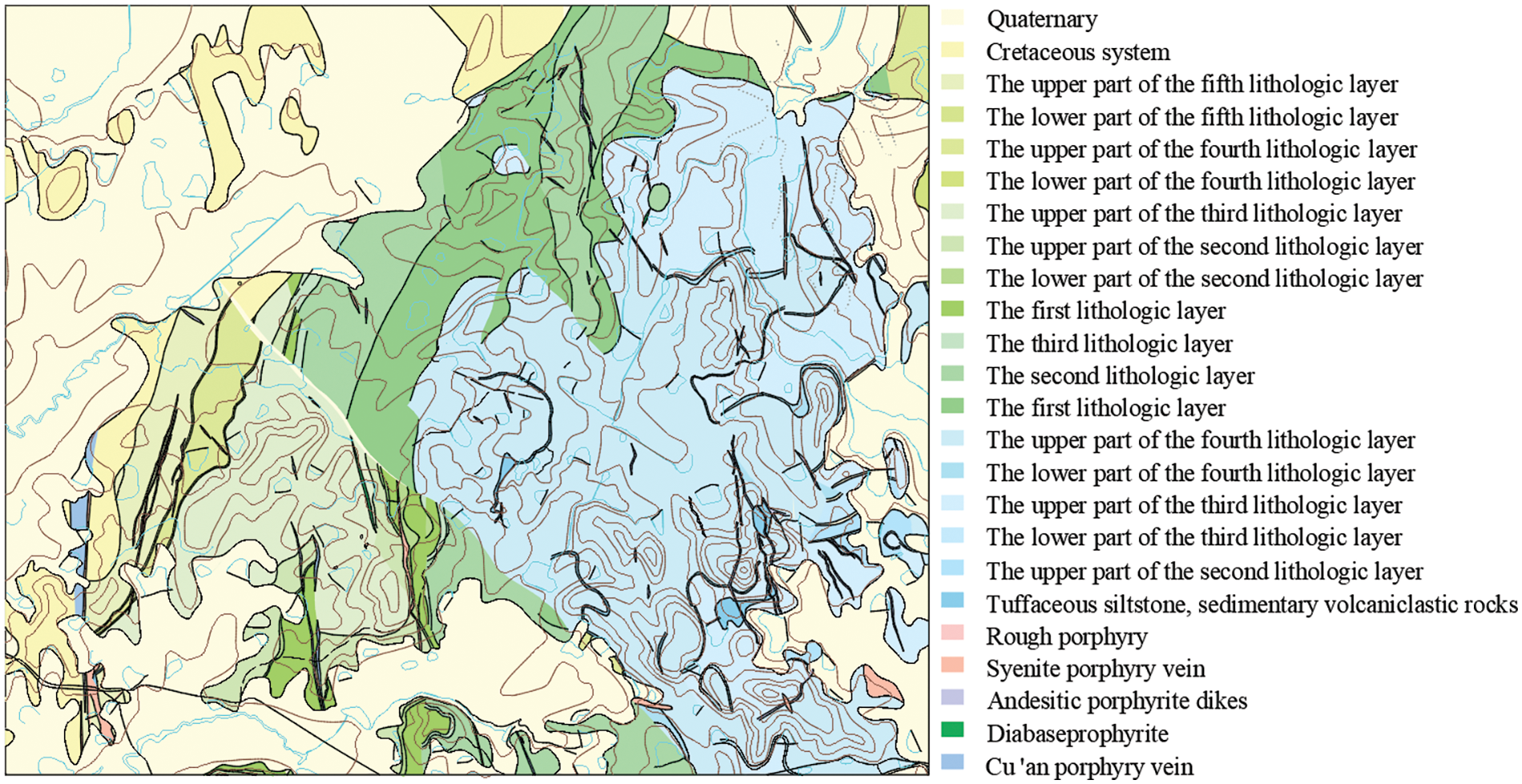
Figure 1: Geological structure map
Based on the shape, dip angle, and thickness of the ore body, as well as other conditions of its occurrence, the majority of the ore bodies north of the II longitudinal exploration line exhibit a vertical open stoping at the deep hole stage and subsequent backfill, and the corners of the ore body exhibit point column, upward stratified filling mining, or medium-deep hole, sublevel open stoping and subsequent backfill. The majority of ore bodies located south of the II longitudinal exploration line were extracted with the use of sublevel open stoping with a medium-deep hole and subsequent backfill, and the corners of the ore body exhibit point column, upper stratified filling mining.
2.2 Filling Borehole Structure
Three filling series were established at the Luohe Mine filling station. Each series was equipped with two boreholes: one for working and one for standby. The borehole in the Quaternary layer had a diameter of φ370 mm and was cased inside a φ273 × 10 mm tubing. Upon borehole reaching the bedrock, the dimension of borehole call for a φ250 mm diameter with no casing. High-grade cement slurry was used for well cementation. After the well was cemented, a bimetallic composite, wear-resistant pipeline was installed in the borehole. The pipeline dimension was φ203 × 26 mm (with a wear-resistant layer of 14 mm). A schematic diagram of the filling borehole structure is shown in Fig. 2. The windstone gate employed a high manganese wear-resistant pipeline with a diameter of φ159 × 12 mm, and the return air roadway and main roadway used ordinary steel pipelines having the same diameter. The branch pipelines of the stope were 6-inch and 4-inch PE pipelines and steel composite pipelines, respectively.
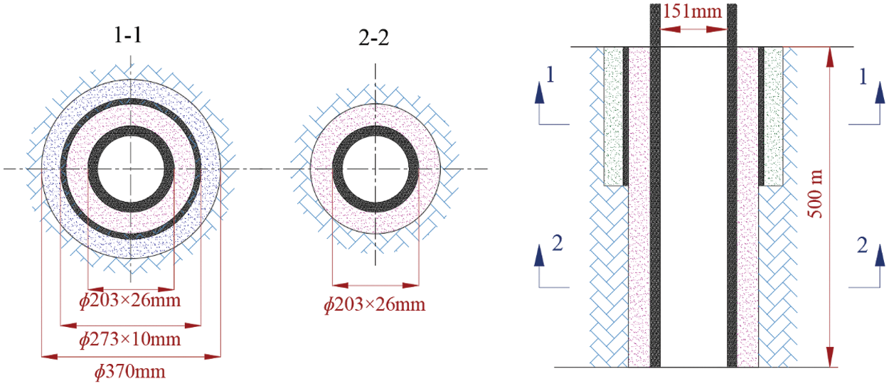
Figure 2: Schematic diagram of the structure of the filling borehole
Pipeline plugging accidents have frequently occurred in the #2-1 borehole of Luohe Mine over its several years of operation. These accidents have had a serious impact on mine production. A high-definition camera was used to scan the hole to check for breakage and blockage of the inner wall of the borehole. The location of the damaged section was then recorded. It was found that the sections at 80, 130, 170 and 230 m were seriously damaged. A scanning image of the inner wall of the borehole is shown in Fig. 3. It is evident in Fig. 3 that, under the impact and friction of the slurry, the inner wall of the borehole has broken and become exposed to the bedrock. Dredging only the drilling rig will not solve the root cause of the pipeline blockage.
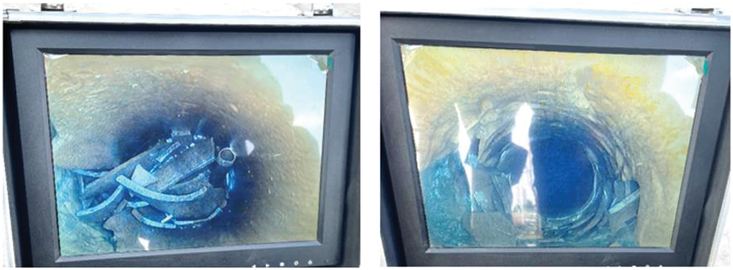
Figure 3: Scanned image of the inner wall of the borehole
(1) Electromagnetic flowmeters
An electromagnetic flowmeter from Yuyao Yinhuan Flow Meter Co., Ltd., Ningbo City, China consisting of a sensor and a converter, was used. A flowmeter is an inductive instrument for measuring the volume flow of a conductive medium, as shown in Fig. 4. This study used an electromagnetic flowmeter to monitor the flow of the filling slurry in the borehole, and the data were recorded at one-minute intervals. The main technical parameters are shown in Table 1.
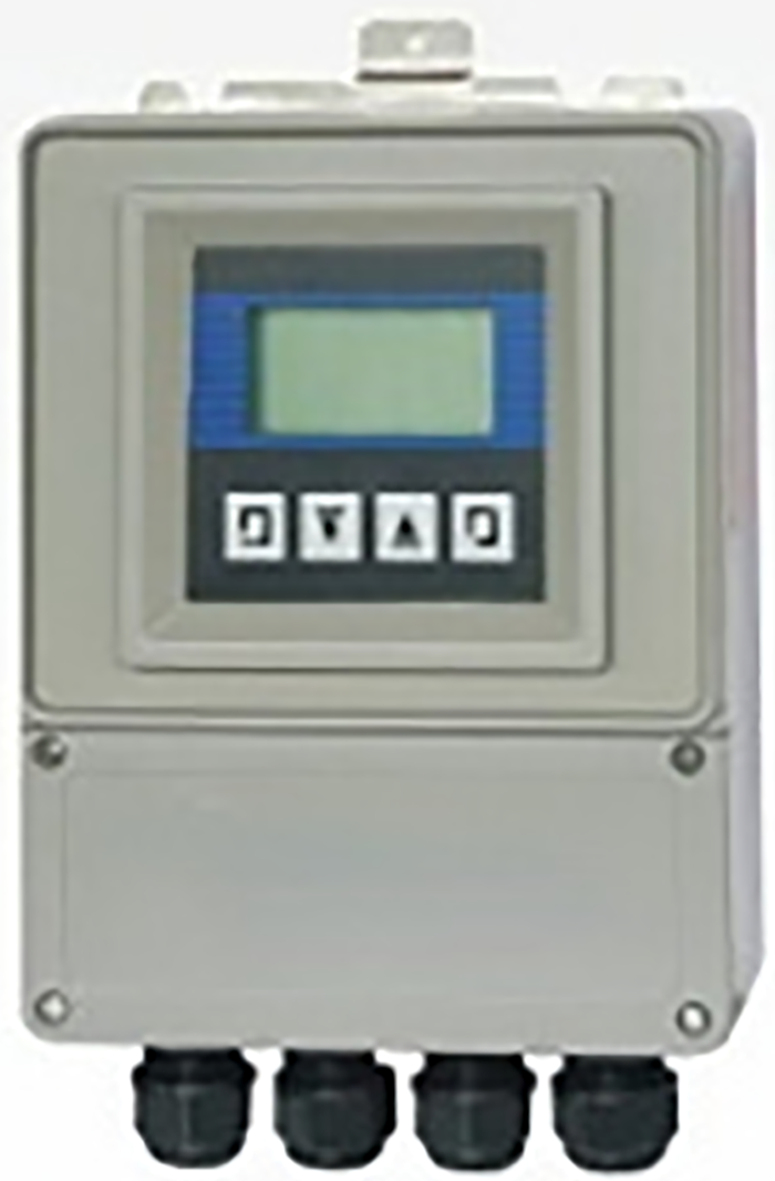
Figure 4: Electromagnetic flowmeters

(2) Radioactive density gauge
The radioactive densitometer was manufactured by EcoPhysPribor, Russia, and it was used for the noncontact measurement of the basic parameters, such as the slurry and fluid density, during various flow processes in the pipeline. The device is shown in Fig. 5. The density of filling slurry in the field environment can be continuously monitored by the device, and the resulting density value is output as a signal. Data are recorded at one-minute intervals. The main technical parameters are shown in Table 2.
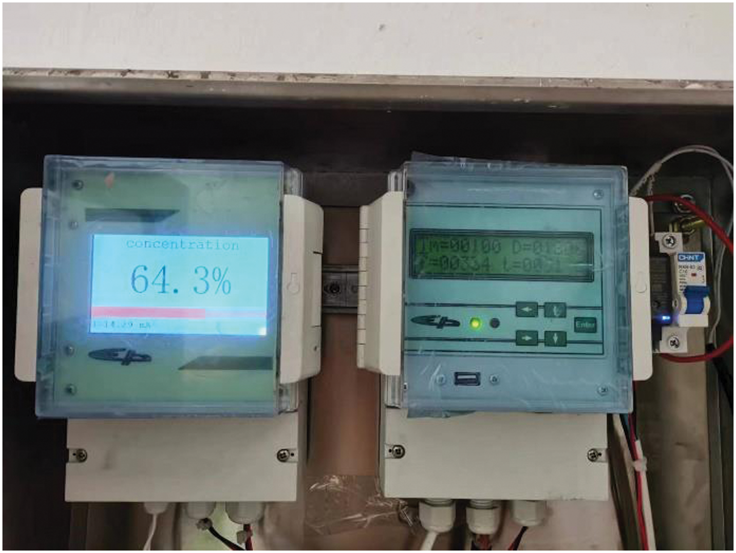
Figure 5: Radioactive density gauge

2.4 Basic Characteristics of Filling Slurry
The mined-out area at Luohe Mine is treated using the total tailings cemented filling technology. The tailings originated from a beneficiation plant. After it was thickened by a deep cone, low-concentration tailings slurry was mixed with cementing material in a mixing barrel and then transported to the mined-out area. The concentration of filling slurry was 68%–69%, and the cement-to-sand ratio was 1:10. The sand produced at the beneficiation plant was classified into two categories: 3 series and 2 series. The concentration of sand in the 3 series was approximately 55%, with a dry sand flow rate of 360 t/h. In the 2 series, the sand concentration was approximately 40%, and the dry sand flow rate was 270 t/h.
The tailings mortar was collected from the bottom of the deep cone thickener and then sampled using the standard quartering method after it was dried. The physical parameters of the total tailings were measured and analyzed using a pycnometer and a Topsizer laser particle size analyzer. The basic physical properties of the total tailings are presented in Table 3.

At a concentration of 68%, the slurry had a bulk density of 1.82 g·cm−3. The yield stress and viscosity were measured under different ratio conditions using the Brookfield R/S plus rheometer equipped with a V40-20 slurry rotor. The measured rheological parameters are listed in Table 4. The yield stress of the slurry is within 100 Pa when the mass concentration is between 66% and 68%, which results in better fluidity of the filling slurry.

3 Research Methods and Program Implementation
The nested repair technology for filling boreholes involves placing a casing as a drill pipe into the hole. If the inner diameter of the casing is too large, this may significantly increase the difficulty of repair and may even prevent its insertion into the existing filling borehole. If the inner diameter is too small, this will increase the resistance along the pipe and affect the self-flow distance of the filling slurry. Therefore, given the current technical conditions of a small aperture (151 mm), it is crucial to determine the appropriate casing size and to develop a scientifically sound construction plan.
3.1 Determination of Basic Casing Parameters
The drilling depth is approximately 500 m. When the casing is lowered, it is necessary to overcome both its own weight and the screw thread rotation torque. Thus, the chosen casing material was a bainite seamless steel pipeline with high strength and excellent wear resistance. The pipelines were connected using screw threads.
The original bimetallic composite pipeline had an inner diameter of 151 mm. It is recommended to reserve 9.5 to 12.7 mm of space for the cement slurry, according to engineering practice. The inner diameter of the original pipeline must be 25.4 mm larger than the outer diameter of the casing, and the outer diameter of the casing must not exceed 132 mm. Based on the hydraulic formula, the pipeline’s maximum hydrostatic pressure is at its lowest point, and it measures approximately 8.94 MPa. The performance standard for the pipeline material requires the thickness of the pipeline layer that bears pressure to be greater than 6 mm. According to the requirements of mine production, the pipeline must have a service life of at least 5 years. Therefore, the wear-resistant layer of the pipeline should be no less than 5 mm thick. Following this analysis, two types of pipelines with inner diameters of 100 and 80 mm were found to meet the specified conditions. The relevant parameters are presented in Table 5.

3.2 Conveying Resistance of Different Pipeline Diameters
The Buckingham formula [23,24] is used to analyze the pipeline resistance under different pipeline diameters, as shown in Eq. (1):
where i is the resistance during slurry transportation, Pa/m; τ0 is the slurry yield stress, Pa; v is the slurry flow speed, m/s; μ is the slurry viscosity, Pa·s.
Fig. 6 shows the change in the pipeline resistance for a pipeline diameter of 100 mm. It is evident in Fig. 6 that at an inner pipeline diameter of 100 mm, slurry concentrations of 66% and 68% are suitable for gravity transportation at a rate of 240 m3/h. When the slurry concentration is 70%, the maximum flow rate for gravity transportation is 120 m3/h.
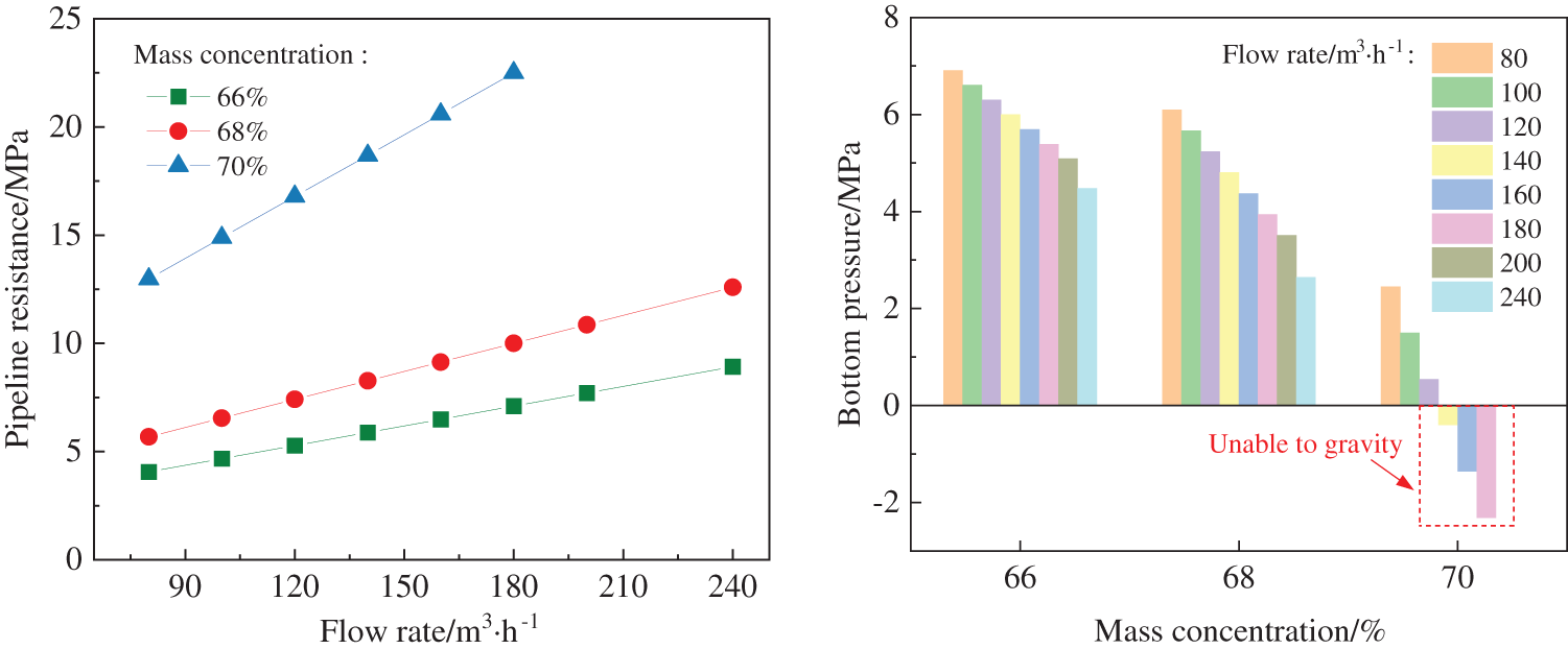
Figure 6: Pipeline resistance under different flow conditions (100 mm inner diameter)
Fig. 7 illustrates the change in pipeline resistance for an 80 mm diameter pipeline. It can be seen from Fig. 7 that the maximum flow rate for the self-flow transportation of filling slurry of 68% concentration is 120 m3/h within a pipeline having a diameter of 80 mm. The resistance of the pipeline is inversely proportional to its inner diameter. Reducing the diameter of the pipeline results in increased resistance. The gravity of the slurry alone may not be sufficient to overcome this resistance. Therefore, the slurry cannot flow at such a high speed in the vertical pipeline and can only be pumped to replenish energy [25]. If a pipeline having an inner diameter of 80 mm is used, the filling slurry concentration must be reduced to have sufficient power [26,27]. Maintaining the appropriate slurry concentration is crucial to ensure filling quality. It is important to note that improving fluidity by reducing slurry concentration may have a significant impact on stope stability. Furthermore, even if the flow rate is reduced to 80 m3/h, the length of the horizontal pipeline for filling slurry self-flow transportation is only 950 m. The maximum distance of underground horizontal pipelines is approximately 2300 m. However, pipelines having an inner diameter of 80 mm do not meet the requirements for mine production.
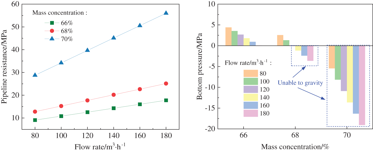
Figure 7: Pipeline resistance under different flow conditions (80 mm inner diameter)
3.3 Different Distances of Self-Flow Conveying
The mine utilizes gravitational potential energy to transport the slurry. The distance of gravity transport is directly affected by the amount of pipeline resistance. Based on the analysis above, it is evident that the pipeline resistance is excessive when the pipeline diameter is 80 mm, and thus, this diameter fails to meet the production requirements of a mine. Therefore, this calculation only considers the self-flow transport distance of horizontal pipelines having different flow rates, given a pipeline with a 100 mm diameter. The calculation results are shown in Table 6, and the coverage of self-flow transport is shown in Figs. 8–10. When the filling flow rate is 80 m3/h, the self-flow distance of the horizontal pipeline is 2.27 km, and the stope can be fully self-filled at 455 m underground. When the filling flow rate is 140 m3/h, the self-flow distance of the horizontal pipeline is 1.39 km. At the −455 m stage, self-flow is capable of transporting slurry to most of the stopes, with only a few areas in the southwest corner unable to be covered. When the filling flow rate is 180 m3/h, the horizontal pipeline can support self-flow up to a distance of 0.99 km, allowing approximately half of the stopes at the −455 m stage to be serviced through self-flow.

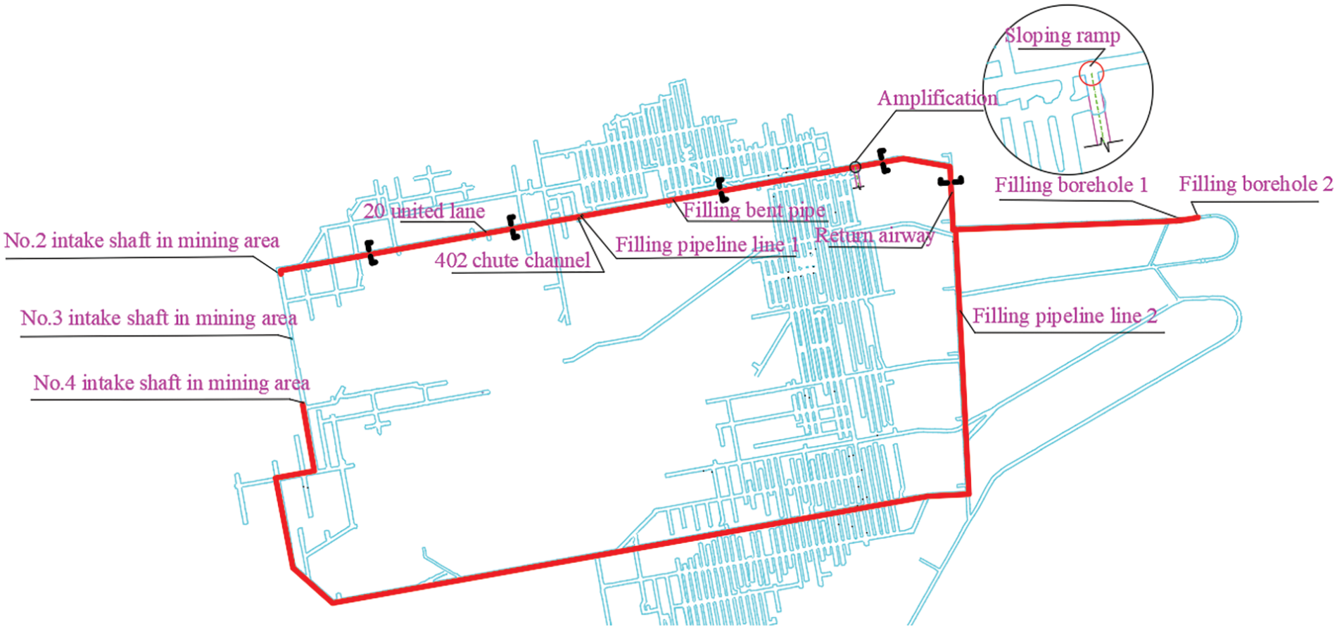
Figure 8: Self-flow coverage at 80 m3/h
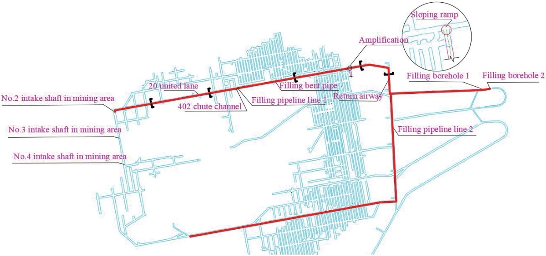
Figure 9: Self-flow coverage at 140 m3/h
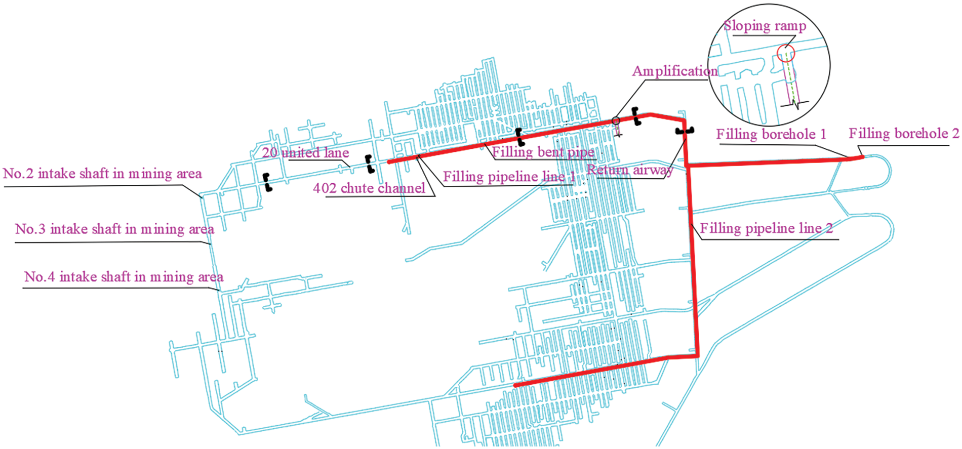
Figure 10: Self-flow coverage at 180 m3/h
It is important to acknowledge that there may be a discrepancy between the self-flow transport coverage calculated according to rheology and the value in practice, which could result in a larger self-flow transport coverage. In summary, the casing’s inner diameter is 100 mm, the pipeline’s wall thickness is 13.5 mm, the length of a single pipeline is 6.0 m, and the calculated unilateral gap is 12.0 mm. However, when a well that is 500 m deep is drilled, some deflection during the construction of the original borehole is inevitable. The deflection distance is often much larger than the gap spacing. If the casing becomes bent and stuck during the construction process, all previous efforts may become wasted. Therefore, the scientific scheme of lowering a casing pipeline is the core of borehole repair technology.
3.4 Construction Scheme for Filling Borehole Nested Repair
The damaged parts of the filling pipeline often exhibit lining uplift, or the lining may peel off. The inner diameter of the borehole may be thinned to varying degrees, which leads to the bending deformation of the pipeline when the casing pipeline is lowered or the inability to withdraw the casing. Deformation may ultimately cause the pipeline to become stuck. In current technology, if there is significant damage to the borehole, a drill pipe is typically used to fully dredge the drill bit to ensure the inner wall is smooth before positioning the casing. However, the gap between the single-sided pipeline wall is only 12 mm and dredging the borehole only ensures that the drill pipeline is unobstructed when the drill pipe is lowered. It could still be blocked or even become stuck when the casing is lowered. To address this issue, a construction scheme is proposed that involves installing a drill bit beneath the casing and lowering the casing into the borehole as if it were a drill pipe. In cases of significant damage, the drill bit can be utilized to rotate and impact obstacles, which significantly increases the likelihood of successful construction.
Due to the threaded connection between the pipelines, there are no redundant connecting parts on the external surface, and the pipeline appears smooth. Insufficient clamping force can cause the pipeline to fall off, which results in the entire borehole being discarded and poses a significant risk. Therefore, to ensure pipeline stability and to prevent it from falling off the well, a combination of pneumatic and manual chucks is used.
It is not possible to determine the damage or the blockage of the filling pipeline after it has been plugged. If the internally damaged fragments are not cleaned completely, the problem of “pipeline sticking” may easily occur during the process of lowering the casing. Therefore, for a less problematic construction, it is necessary to clean the inner walls before lowering the casing. The design of a construction process based on the above considerations is shown in Fig. 11, and an on-site construction drawing is shown in Fig. 12.
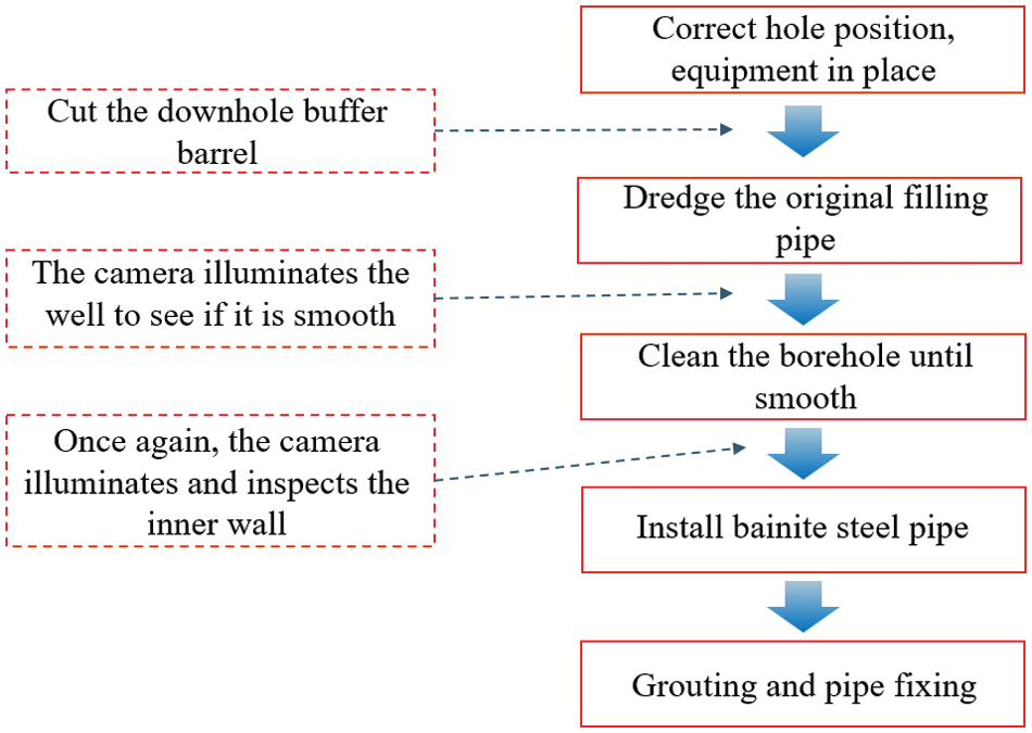
Figure 11: Flowchart for the construction of a filled borehole nested repair
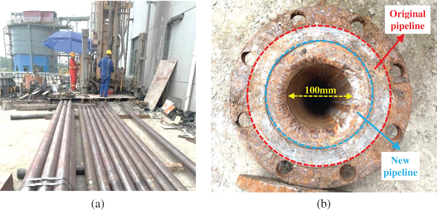
Figure 12: Site construction drawing of the lower casing. (a) Under construction. (b) Construction not yet finished
A reduction in pipeline diameter from 151 to 100 mm results in a decrease in filling flow and limits filling efficiency. To determine the filling capacity of the new borehole, we collected and processed the parameters of the stope, such as filling flow and slurry concentration, at different distances from the quarry after repair. The filling data obtained are presented in Figs. 13 and 14. The data show that the flow rate of the new borehole filling remains relatively stable. Any fluctuations are primarily caused by changes in concentration, with the flow rate decreasing as the concentration increases. As the concentration increases, the water film adsorbed onto the surface of the particles gradually becomes thinner. This results in poor lubrication between the particles, a rapid increase in pipeline transportation resistance, and a reduced rate of flow.
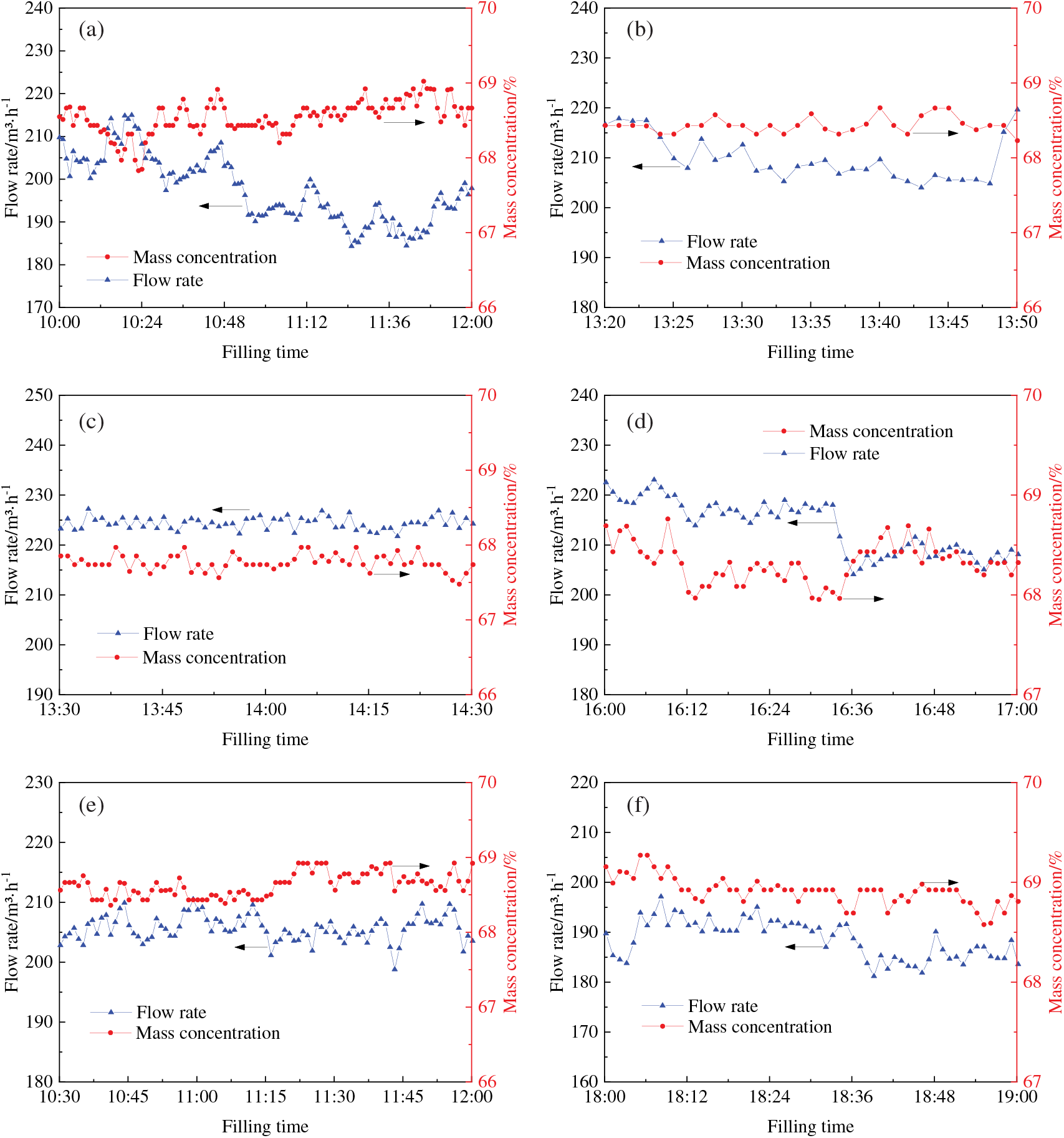
Figure 13: Variation in filling flow rate and mass concentration of new pipeline at different distances from the quarry (inner diameter 100 mm). Stope: (a) #28-9, (b) #44-3, (c) #26-9, (d) #46-3, (e) #30-8, (f) #55-3
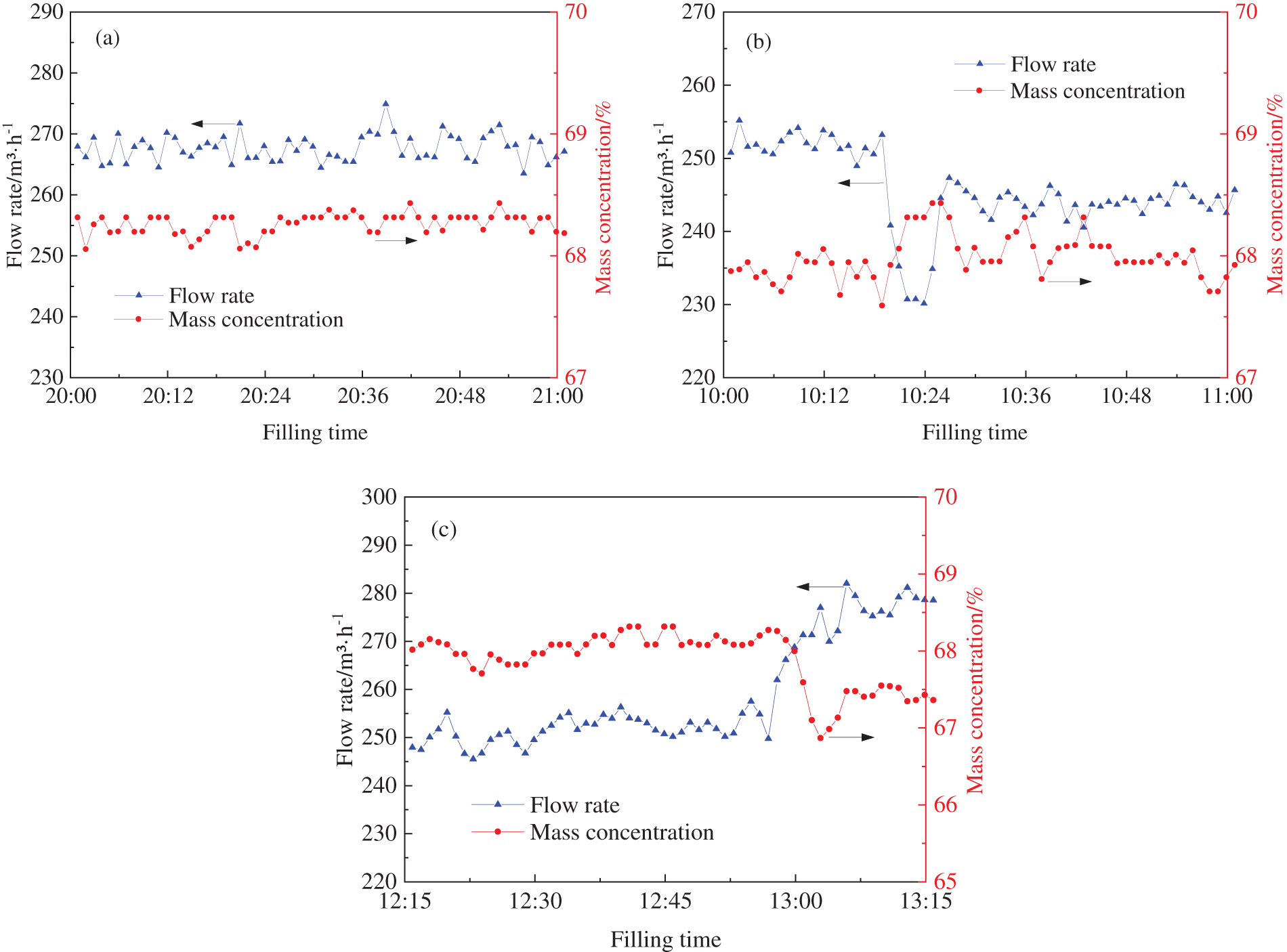
Figure 14: Variation of filling flow rate and mass concentration at different distances from the original pipeline to the quarry (inner diameter 151 mm). Stope: (a) #55-3, (b) #26-8, (c) #33-10
Table 7 shows the summary of the average filling flow at various distances from the quarry. When the new pipeline is used with an inner diameter of 100 mm for filling, the transportation flow rate is 188.60–224.39 m3/h. When the inner diameter is 151 mm, the transportation capability is between 245.58 and 267.71 m3/h. The flow rate is typically reduced when the pipeline diameter decreases and when resistance increases. However, after the diameter of the pipeline is reduced, the filling pipeline achieves transport for long-distance stopes as well. For example, the horizontal pipeline distance for the #44-3 stope is 2319.6 m, and the average filling flow can reach 209.83 m3/h. In order to explore whether the filling capacity of the modified filling boreholes matches production requirements, the consumption of tailings sand in the filling boreholes was calculated. The calculation formula is shown in Eq. (2):
where W is the amount of tailings consumed per hour by filling a single borehole, t; Q is the filling flow, 200 m3/h; ρ is the filling slurry density, 1.82 t/m3; C is the filling slurry mass concentration, 68%; n is the slurry sand cement ratio, 10.

After the aforementioned parameters were substituted into Eq. (2), the value of W was calculated as 225 t. This calculation, which was conducted under the most unfavorable conditions, indicates that the amount of sand from the 3 series for the beneficiation plant is 360 t/h, whereas the amount of tailings that can be filled by the two boreholes simultaneously is 450 t/h. Consequently, the pipeline is capable of meeting the filling demand of stope following the transformation.
Since the repair of the filling borehole in May 2022, a total of 1,000,000 m3 of material has been injected into the borehole. No incidents, such as lining shedding or pipeline plugging, have been noted. The inside of the borehole is smooth and shows some normal wear. As shown in Table 8, compared with the reconstruction of a filling borehole, the cost was reduced by approximately 1.2 million yuan, and the construction time was shortened by between 1 and 4 months. In addition, 6 filling boreholes in the mine were saved. It is anticipated that the service life will be more than doubled, and significant potential for application in the backfill mines.

(1) Rheology theory was employed to investigate pipeline resistance and self-flowing distance under different working conditions. The results demonstrated that when the inner diameter of the pipeline was 100 mm, slurry having a concentration of 66% and 68% achieved a self-flow transport capacity of 240 m3/h. When the inner diameter of the pipeline was 80 mm, the flow rate limit of self-flow transport for slurry having a concentration of 68% was 120 m3/h.
(2) A construction scheme for nested repair was designed, and a construction scheme for installing a drill bit under the casing and using the casing as the drill pipe in the damaged borehole was proposed. In the event of significant damage to the pipeline, the drill bit could be used to rotate and impact obstacles, thereby greatly enhancing the probability of successful construction.
(3) When the repaired pipeline was used for filling, the transport flow rate was 188.60–224.39 m3/h. For the long-distance stope (a horizontal pipeline distance is 2319.6 m), the average filling flow rate reached 209.83 m3/h. By calculating the consumption of tailings during the filling of boreholes, we verified that the new filling pipeline met the requirements for mine production.
(4) In comparison with redrilling, the filling borehole repair technology saves both money and time and more than doubles the service life of filling borehole. This meets the production needs of the mine and has good application value in filling mining.
Acknowledgement: All authors are grateful for the hard work of the journal editorial office.
Funding Statement: This research was supported by the State Key Research Development Program of China (2018YFC0603705) and the Fundamental Research Funds for the Central Universities (FRF-IDRY-GD22-004).
Author Contributions: The authors confirm contribution to the paper as follows: Writing—original draft, Funding acquisition, Resources: Yijun Gao. Conceptualization, Project Administration, Supervision: Yong Wang. Writing—original draft, Investigation: Qing Na. Writing—review & editing: Jiawei Zhang. Supervision: Aixiang Wu. All authors reviewed the results and approved the final version of the manuscript.
Availability of Data and Materials: The data used to support the findings of this study are available from the corresponding author upon request.
Ethics Aproval: Not applicable.
Conflicts of Interest: The authors declare that they have no conflicts of interest to report regarding the present study.
References
1. Cheng HY, Wu AX, Wu SC, Zhu JQ, Li H, Liu J, et al. Research status and development trend of solid waste backfill in metal mines. Chin J Eng. 2022;44(1):11–25 (In Chinese). [Google Scholar]
2. Krupnik LA, Shaposhnik YN, Shaposhnik SN, Tursunbaeva AK. Backfilling technology in Kazakhstan mines. J Min Sci. 2013;49(1):82–9. doi:10.1134/S1062739149010103. [Google Scholar] [CrossRef]
3. Wang ZQ, Wang Y, Cui L, Bi C, Wu AX. Insight into the isothermal multiphysics processes in cemented paste backfill: effect of curing time and cement-to-tailings ratio. Constr Build Mater. 2022;325:126739. [Google Scholar]
4. Wu AX, Wang Y, Ruan ZE, Xiao BL, Wang JD, Wang LQ. Key theory and technology of cemented paste backfill for green mining of metal mines. Green Smart Min Eng. 2024;1(1):27–39. doi:10.1016/j.gsme.2024.04.003. [Google Scholar] [CrossRef]
5. Yang ZQ, Wang YQ, Gao Q, Zhao CW. The practical management experience on design and construction of filling pipes and boreholes. J Xuzhou Inst Technol (Nat Sci Ed). 2016;31(2):14–9 (In Chinese). [Google Scholar]
6. Deng DQ. Failure and treatment mode of filling boreholes in chinese mines. China Tungsten Ind. 2018;33(3):9–13 (In Chinese). [Google Scholar]
7. Alam T, Islam MA, Farhat ZN. Slurry erosion of pipeline steel: effect of velocity and microstructure. J Tribol. 2009;138(2):021604. doi:10.1115/1.4031599. [Google Scholar] [CrossRef]
8. Gericke D. The working life of a pipeline carrying an abrasive slurry. In: Slurry Handling and Pipeline Transport: Hydrotransport. 14; 1999. p. 719–37. [Google Scholar]
9. Xiong YW. Failure analysis and preventive measures of filling borehole in deep mine. Modern Min. 2016;32(10):225–7 (In Chinese). [Google Scholar]
10. Patil MS, Deore ER, Jahagirdar RS, Patil SV. Study of the parameters affecting erosion wear of ductile material in solid-liquid mixture. In: Proceedings of the World Congress on Engineering, 2011; London, UK. vol. 3, p. 2159–63. [Google Scholar]
11. Creber KJ, Kermani MF, McGuinness M, Hassani FP. In-situ investigation of mine backfill distribution system wear rates in Canadian mines. In: Proceeding of 16th International Symposium on Environmental Issues and Waste Management in Energy and Mineral Production (Swemp 2016), 2016; Istanbul, Turkey. [Google Scholar]
12. Cunliffe CJ, Dodds JM, Dennis DJC, Trias FX. Flow correlations and transport behaviour of turbulent slurries in partially filled pipes. Chem Eng Sci. 2021;235(3):116465. doi:10.1016/j.ces.2021.116465. [Google Scholar] [CrossRef]
13. Zhu X, Wu FF, Yin XY, Liu Y, Wang XY. Simulation study on resistance and wear of filling transportation pipeline of tailing cemented filling slurry. Min Res Dev. 2022;42(3):120–4 (In Chinese). [Google Scholar]
14. Zhang QL, Cui JQ, Zheng JJ, Wang XM, Wang XL. Wear mechanism and serious wear position of casing pipe in vertical backfill drill-hole. T Nonferr Metal Soc. 2011;21(11):2503–7. doi:10.1016/S1003-6326(11)61042-X. [Google Scholar] [CrossRef]
15. Gharib N, Bharathan B, Amiri L, McGuinness M, Hassani FP, Sasmito AP. Flow characteristics and wear prediction of Herschel-Bulkley non-Newtonian paste backfill in pipe elbows. Can J Chem Eng. 2017;95(6):1181–91. doi:10.1002/cjce.22749. [Google Scholar] [CrossRef]
16. Feng JE, Wu C. Fuzzy comprehensive evaluation on probability failure criteria of the deep level pipelines filling system. J Cent South Univ. 2005;6:1079–83 (In Chinese). [Google Scholar]
17. Xue XL, Wang XM, Zhang QL. An integrated model of combination weights and variable fuzzy on evaluating backfill pipeline wear risk. J Cent South Univ. 2016;47(11):3752–8 (In Chinese). [Google Scholar]
18. Wang XM, Gao RW, Hu W, Feng Y, Zhou DH. Risk prediction model of filling pipeline blockage. J Cent South Univ. 2013;44(11):4604–10 (In Chinese). [Google Scholar]
19. Wang P, Li JQ, Li YB, Liu L, Qin XB, Zhang B. Visual detection method of metal mine filling pipeline blockage based on ERT. J Cent South Univ. 2022;53(2):643–52 (In Chinese). [Google Scholar]
20. Wang EJ, Zhao GY, Wu H, Liang WZ, Li ZY. Weight-variation-fuzzy model for assessing wear risk of backfilling pipeline and its application. China Saf Sci J. 2018;28(3):149–54 (In Chinese). [Google Scholar]
21. Sun YM, Zhang HM, Huang MJ, Liu ZY. Wear analysis and countermeasures of filling hole in Zhangzhuang Mine. Modern Min. 2021;37(10):247–8 (In Chinese). [Google Scholar]
22. Guo SJ. Permanent repairable technology for damaged filling hole in Jinchuan mining area. China Min Eng. 2011;40(1):1–3 (In Chinese). [Google Scholar]
23. Wang J, Wang YM, Zhang MZ, Peng QS, Jia W. Research on the rheological characteristics of expanded filling slurry and the calculation model of pipeline resistance based on orthogonal test. Met Min. 2022;4:40–5 (In Chinese). [Google Scholar]
24. Ahmed HM, Bharathan B, Kermani M, Hassani F, Hefni MA, Ahmed HAM, et al. Evaluation of rheology measurements techniques for pressure loss in mine paste backfill transportation. Minerals. 2022;12(6):678. doi:10.3390/min12060678. [Google Scholar] [CrossRef]
25. Alehossein H, Shen B, Qin Z, Huddlestone-Holmes C. Flow analysis, transportation, and deposition of frictional viscoplastic slurries and pastes in civil and mining engineering. J Mater Civil Eng. 2012;24(6):644–57. doi:10.1061/(ASCE)MT.1943-5533.0000443. [Google Scholar] [CrossRef]
26. Yang TY, Qiao DP, Wang J, Zhang X, Chen Y. Numerical simulation and new model of pipeline transportation resistance of waste rock-aeolian sand high concentration slurry. J Nonferrous Met. 2021;31(1):234–44 (In Chinese). [Google Scholar]
27. Bharathan B, McGuinness M, Kuhar S, Kermani M, Hassani FP, Sasmito AP. Pressure loss and friction factor in non-Newtonian mine paste backfill: modelling, loop test and mine field data. Powder Technol. 2019;344:443–53. [Google Scholar]
Cite This Article
 Copyright © 2024 The Author(s). Published by Tech Science Press.
This work is licensed under a Creative Commons Attribution 4.0 International License , which permits unrestricted use, distribution, and reproduction in any medium, provided the original work is properly cited.


 Submit a Paper
 Propose a Special lssue
 View Full Text
 Download PDF
 Downloads
 Citation Tools