 Open Access
ARTICLE
Factors Influencing Proppant Transportation and Hydraulic Fracture Conductivity in Deep Coal Methane Reservoirs
1 China United Coal Bed Methane Ltd., Beijing, 100124, China
2 Provincial Center of Technology Innovation for Coal Measure Gas Co-Production, Taiyuan, 030032, China
* Corresponding Author: Fan Yang. Email:
Fluid Dynamics & Materials Processing 2024, 20(11), 2637-2656. https://doi.org/10.32604/fdmp.2024.048574
Received 12 December 2023; Accepted 19 June 2024; Issue published 28 October 2024
Abstract
The gas production of deep coalbed methane wells in Linxing-Shenfu block decreases rapidly, the water output is high, the supporting effect is poor, the effective supporting fracture size is limited, and the migration mechanism of proppant in deep coal reservoir is not clear at present. To investigate the migration behavior of proppants in complex fractures during the volume reconstruction of deep coal and rock reservoirs, an optimization test on the conductivity of low-density proppants and simulations of proppant migration in complex fractures of deep coal reservoirs were conducted. The study systematically analyzed the impact of various fracture geometries, proppant types and fracturing fluid viscosities on proppant distribution. Furthermore, the study compared the outcomes of dynamic proppant transport experiments with simulation results. The results show that the numerical simulation is consistent with the results of the proppant dynamic sand-carrying experiment. Under the conditions of low viscosity and large pumping-rate, a high ratio of 40/70 mesh proppant can facilitate the movement of the proppant to the depths of fractures at all levels. The technical goal is to create comprehensive fracture support within intricate trapezoidal fractures in deep coal and rock reservoirs without inducing sand plugging. The sand ratio is controlled at 15%–20%, with a proppant combination ratio of 40/70:30/50:20/40 = 6:3:1. Proppant pumping operations can effectively address the issue of poor support in complex fractures in deep coal formations. The research results have been successfully applied to the development of deep coalbed methane in the Linxing-Shenfu block, Ordos Basin.Keywords
As a kind of unconventional oil and gas resource, research on coalbed gas has gradually entered deeper layers in recent years, revealing China’s abundant coalbed gas resources. It is known that China’s deep coalbed gas resources geological reserves are about 22.45 trillion m3, accounting for 61% of the total resources [1,2]. The deep coal fracture of Linxing Block and Shenfu Block in Ordos Basin exhibits poor physical properties, high stress, low permeability and strong adsorption capacity. The gas production of gas wells decreases rapidly, the water production is high, the supporting effect is poor, and the effective supporting fracture size is limited. It is urgent to study the applicability of proppants in deep coal fractures and the transportation characteristics of proppants based on the characteristics of the deep coalbed methane reservoir of the Benxi Formation.
The hydraulic fracturing of coal typically results in the formation of a network of branch fractures. The effective placement of proppant within these network fractures is crucial to ensuring the success of hydraulic fracturing in coal formations. Kurlenya et al. [3] identified the main controlling factors of coalbed methane fracturing effect based on Apriori correlation analysis. Msalli et al. [4] simulated the transportation of pulverized coal and proppant in the main fracture and branch fracture, with a focus on the impact of pulverized coal transportation on the permeability of the proppant pack. Based on previous studies, Brannon et al. [5] utilized a novel visual physical simulation device for proppant transport to conduct laboratory tests. They discovered that during the initial stage of proppant pumping, large transportation, low sand ratio and small particle size of proppant carrying fluid were used to effectively fill remote narrow fractures. In the later stage, proppant carrier fluid with a low flow rate, high sand ratio and large particle size was used to fill the near-well interval. Chang et al. [6] analyzed the influences of closing pressure, mechanical parameters of proppant and coal rock, proppant particle size and sand layer number on horizontal fracture conductivity to determine the sequence of main controlling factors of conductivity. Li et al. [7] utilized an enhanced proppant filling fracture conductivity tester to evaluate the effects of proppant particle size, sand concentration, coal-rock elastic modulus, coal powder content and fracturing fluid type on the conductivity of complex fractures in coalbed methane reservoirs, and identified the factors influencing the conductivity of complex fractures in coalbed methane reservoirs. Song [8] studied the effects of fracturing fluid parameters and proppant parameters on the sand deposition area and the effective propping length of the proppant with varying fracture widths. They proposed a method involving a “high pre-fluid ratio, small particle size proppant, low sand ratio, and short slug sand addition method”, which can significantly enhance the fracturing spread range and effective support. Zhang et al. [9] studied the influence of proppant combinations on the propping effect of complex fractures by injecting proppant with different particle sizes into the fractures. Khanna et al. [10] conducted a long-term conductivity experiment on proppant combinations with different particle sizes in complex fracturing. They examined the impact of different particle size combinations on conductivity. Zhang et al. [11] applied the FCES-100 long-term fracture conductivity instrument to test the long-term conductivity of hydraulic fractures in medium and high-rank coal rocks. They considered the variations in mechanical properties among coal rocks of different ranks and proposed a straightforward method to assess the conductivity of complex fractures in coal formations.
Previous studies on the proppant migration rule in fractures of coal and rock reservoirs have primarily focused on medium and shallow coal fractures. In deep coal and rock reservoirs, proppant migration is challenging due to high stress, making sand plugging easy. The mechanism of proppant transportation in complex fractures of deep coal and rock reservoirs remains unclear. Based on the downhole core of the Linxing-Shenfu block in Ordos Basin, this paper conducted research on proppant migration in deep coal fractures. Fluent software was adopted to consider the fluid-solid coupling (fracturing fluid and proppant) and solid-solid coupling during proppant migration. The influence of proppant particle size, sand ratio and fracture shape on proppant migration was studied. The proppant migration rule in deep coal fractures was defined under consideration of multiple factors. The research results have been applied to deep coalbed methane wells in Linxing-Shenfu block, Ordos Basin, and the effect of increasing production is remarkable.
2 Geological Condition of Deep Coal Fracture in Linxing-Shenfu Block
Local micro-cracks develop in deep coal fractures due to high overall ground stress, resulting in significant fracturing construction pressure [12,13]. The maximum principal stress of Linxing gas field ranges from 38 to 62 MPa, with an average of 56 MPa. The minimum principal stress ranges from 21 to 45 MPa, with an average of 39 MPa. The vertical stress ranges from 27 to 53 MPa, with an average of 47 MPa. The pores of deep coal fractures are mainly less than 100 nm, with an average pore size of 19.6 nm.
The average Poisson ratio of Linxing-Shenfu block is 0.38, which is slightly higher than the dynamic and static Poisson ratio of top and floor. The static Young’s modulus of coal fracture is between 3–7 GPa, with an average of 5.9 GPa; the dynamic Young’s modulus is between 6–8 GPa, with an average of 7.2 GPa; the average porosity is 2.2%; The average permeability is 0.03 mD; the coal fracture is characterized by low modulus, high Poisson’s ratio, low strength, and high cut/bedding density. It is difficult to construct the joint network, difficult to add sand in fracturing, easy to plug in sand, and difficult to stabilize long-term production.
Fig. 1 illustrates the core, cuttings, and mechanical properties of 8 + 9# deep coal seam in Linxing-Shenfu block. Upon core observation, it is evident that the 8# coal cuttings exhibit bright coal. The cuttings predominantly consist of 2–5 cm blocks with a long axis angular shape, indicating a well-structured coal body. Some of the bright coal strips in the cuttings exhibit well-developed cleavage characteristics and favorable pore conditions. The adsorption and desorption capacity of anthracite coal is high, and the physical properties of the reservoir are favorable. Improving the productivity of deep coalbed methane wells mainly depends on fractures with high conductivity formed by fracturing. However, the deep coal reservoir is prone to forming complex fractures and a large number of branch fractures in the vicinity of the well. The width of branch fracture seriously affects the proppant filling in deep coal reservoirs. Therefore, this paper comprehensively considers the actual fracture shape of deep coal reservoirs. It establishes a fracture model for deep coal and rock reservoirs with trapezoidal multi-branch fractures and varying fracture width based on Fluent software, which clarified the proppant migration rule in complex fractures of deep coal seam, and indicated the fracture proppant technology suitable for deep coal seam.
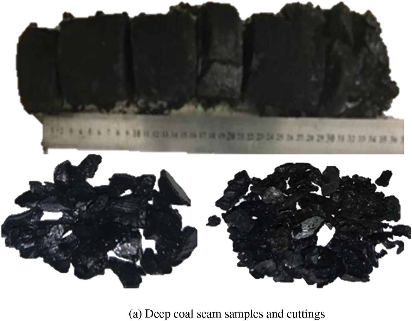
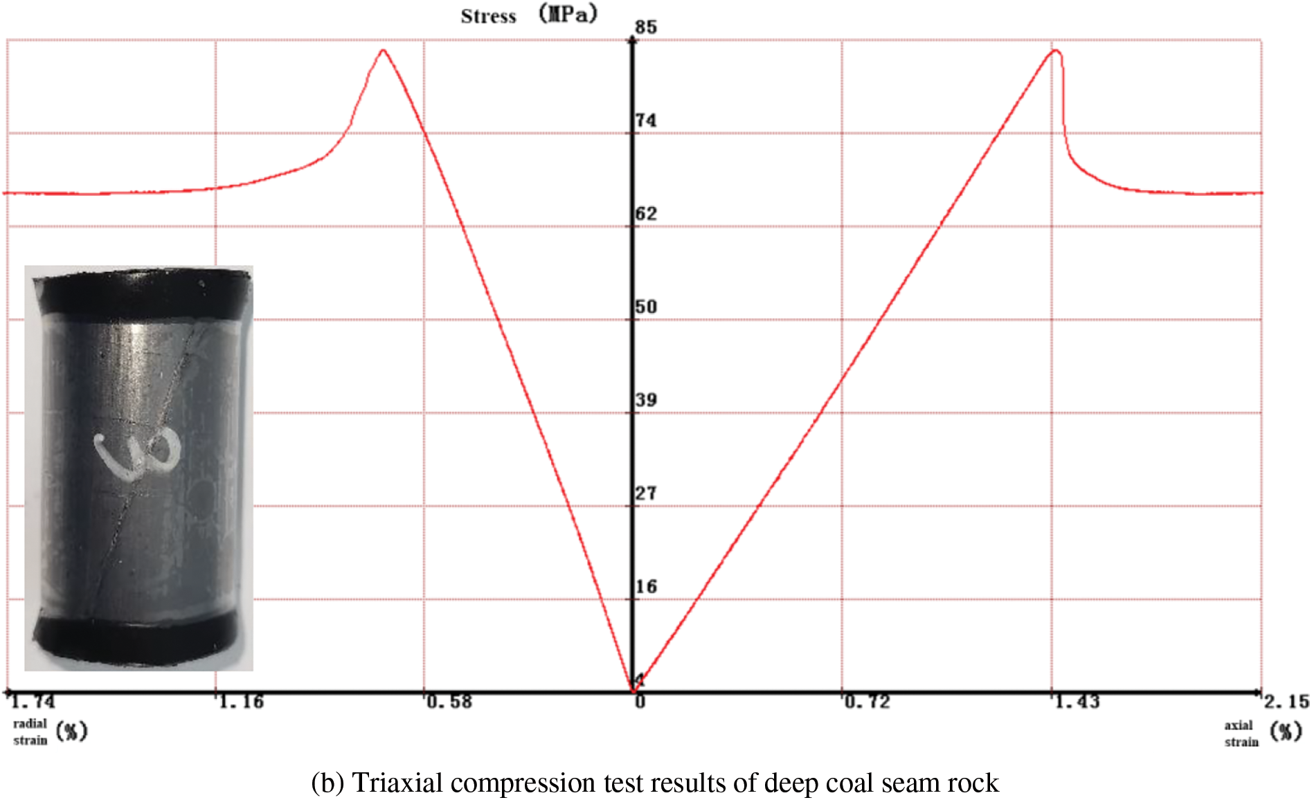
Figure 1: The core observation of deep coal reservoir
3 Preparation before the Experiment
Experimental instrument: FCES-100 deflector [14]; Experimental fluid: 2% KCl solution, fluid flow 2–5 mL/min; Experimental temperature: 50°C–60°C; Experimental pressure: 10, 20, 30, 40, 50 MPa, a total of 5 test pressure points; Experimental time: 0.5 h at single point; Proppant type: Low density ceramic proppant (20/40, 30/50, 40/70 mesh). The specific test scheme and parameters are shown in Table 1. The experimental equipment and schematic diagram are shown in Fig. 2.

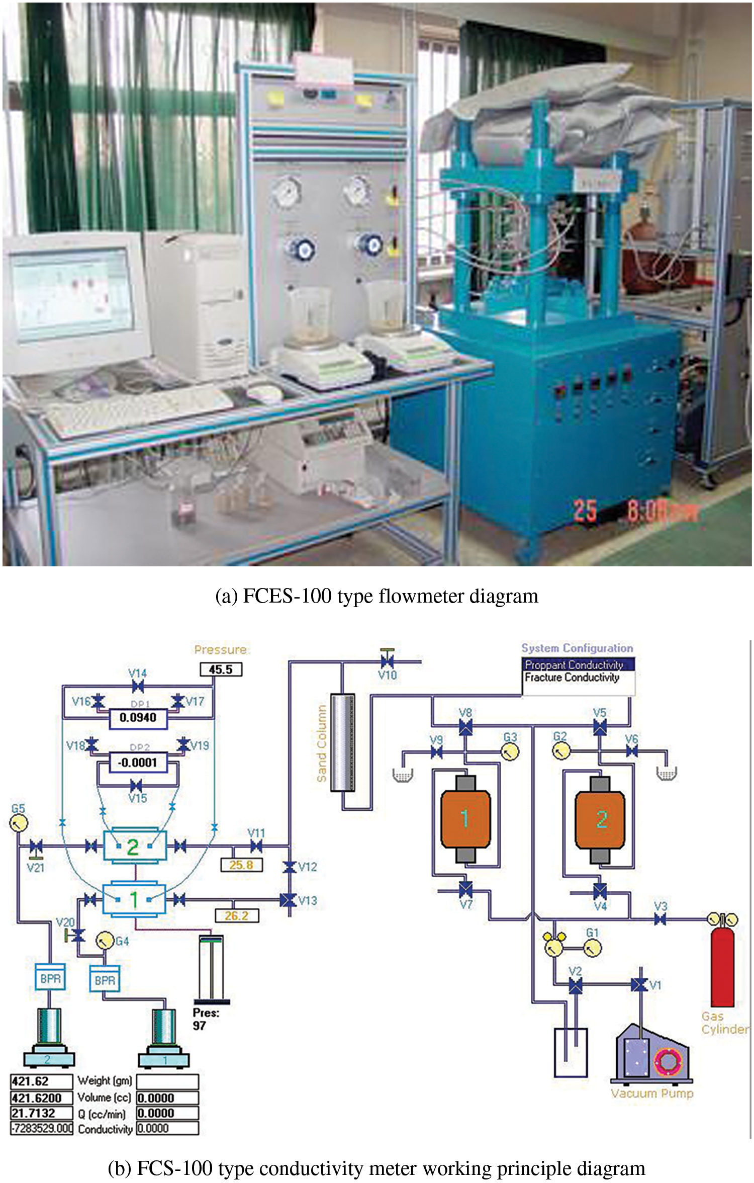
Figure 2: Device and working principle of conductivity measurement experiment
The actual underground core in Linxing-Shenfu block was selected for the experiment. The natural coal and rock with a diameter of 6 cm is processed into a coal and rock flow guide sheet with a size of 17.7 cm long, 3.8 cm wide and 1–2 cm thick, and the end is semicircular, as shown in Fig. 3.
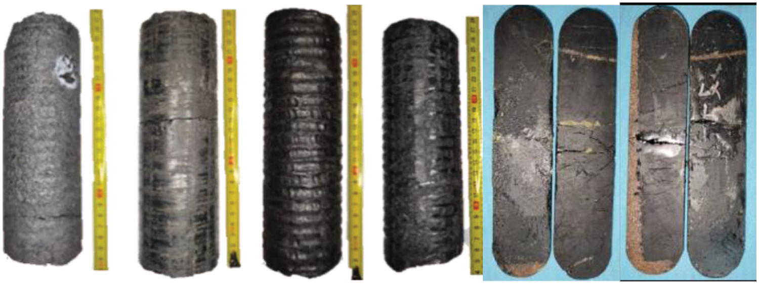
Figure 3: The core and coal rock slab in Linxing-Shenfu block of deep coal fracture
In the experiment, FCES-100 conductivity meter was used to clamp coal sheets in the conductivity chamber to simulate coal fracture fractures, and the experimental fluid passed through the proppant filled layer between two coal sheets at a steady flow rate, and gradually increased the closing pressure to obtain the curve of the fracture conductivity changing with the closing pressure [14–16]. By changing the proppant particle size combination, the curves of the relationship between the closing pressure and the flow conductivity under different conditions were obtained, and the proppant particle size combination scheme was optimized.
3.4 The Numerical Simulation Model of Proppant Transportation Was Established
Considering the similarity criterion [17–19], the length and height of the simulated hydraulic fracture are determined to be 7500 and 1500 mm, respectively, and the influence of the fracture width on proppant transportation is simulated by changing the width of the fracture. In order to improve the accuracy and convergence speed of the calculation, the grid division is structured. Considering that the crack of the model is a regular rectangular structure and the size of the length direction is large, the mesh size is set to 5 mm × 5 mm, 1500 grids in the length direction and 300 grids in the height direction. The quadrilateral structure grid type is used to divide the geometric model into grids, as shown in Fig. 4. The boundary condition of the entrance is the velocity entrance, and the part of the middle fracture height of 10 mm × 10 mm is selected as the constant velocity entrance to simulate the perforation of the fracturing section. The outlet boundary condition is the pressure outlet, and the part of 10 mm × 10 mm at the top of the fracture is selected as the constant pressure outlet to simulate the filtration process of fracturing fluid. The boundary condition of other parts of the model is the wall surface, and the wall surface is assumed to be non-slip wall and the temperature is constant. The Realizable model in the K-epsilon model was used to describe the proppant flow in the fracture, and the turbulence intensity and hydraulic equivalent diameter at the inlet were set to improve the accuracy of the calculation. In addition, the Coupled algorithm is used to solve the pressure and velocity coupling field, and the pressure is PRESTO! Discrete format, and other first-order discrete format.
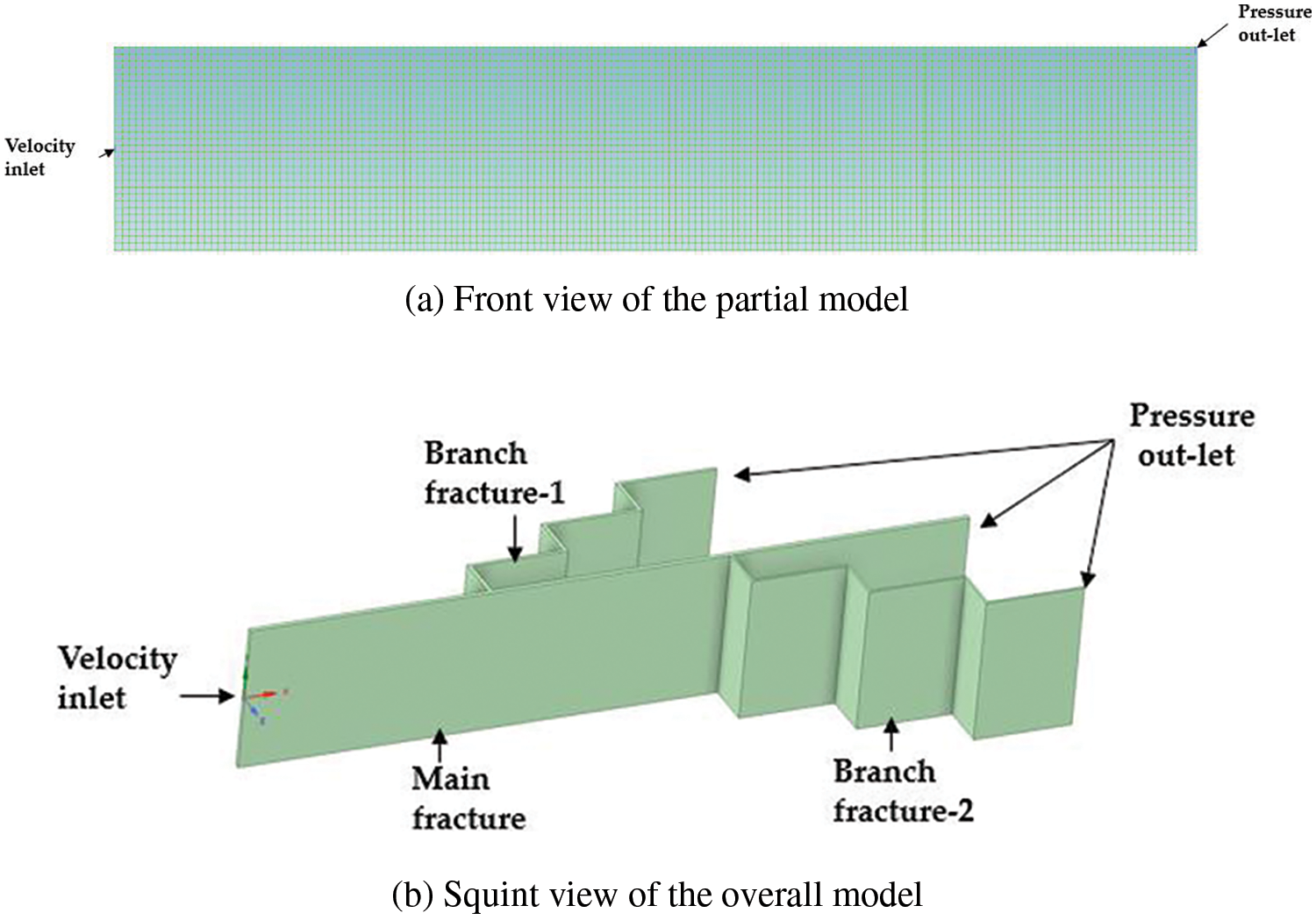
Figure 4: Proppant transportation model in deep coal fracture
The numerical simulation of proppant migration and placement in complex fractures is mainly based on the use of Fluent software to simulate proppant migration, mainly considering the multiphase flow model and viscosity model. The Eulerian model and k-ε model were used for numerical simulation. The k-ε model was Realizable module. Euler model is used to solve the multiphase flow, which usually solves the momentum equation and the continuity equation separately, and the mixed model is a simplified Euler model, which is suitable for proppant migration and settlement.
In addition, the calculation amount of the hybrid model is small and the precision is high. Considering the interaction between fracture fluid and proppant, proppant and wall surface, a mathematical model of solid-liquid two-phase flow was established based on fluid flow equation and proppant settlement equation. The mathematical model of proppant migration in complex fractures in deep coal seams includes fluid control equation, control equation considering proppant embedment particle [20] and proppant embedment equation [21]. Among them, the fluid control equation includes continuity equation, momentum conservation equation and energy conservation equation, and the equations are as follows:
where, αf, ρf, uf and t are the volume fraction, density, velocity and injection time of the fluid, respectively. p, g, τ and S are fluid pressure, gravitational acceleration, viscous stress tensor (mainly determined by viscosity) and momentum source phase (related to particle phase), respectively. cp, T, k and ST are the specific constant pressure heat capacity, temperature, heat transfer coefficient and internal heat source (viscous dissipation term), respectively.
Particle governing equation:
The mass conservation equation of sand carrying fluid in fracture is as follows:
In the formula, ρp is the equivalent density of density proppant, kg/m3; vp is proppant particle velocity, m/min.
The migration velocity of proppant particles in the fracture was as follows:
where, vt is the corrected sedimentation velocity of Stoke particles, m/min; vp is the average velocity of proppant particles in x direction, m/s; vf is the average fracturing fluid velocity m/s; The corrected Stoke sedimentation velocity vt can be obtained by Eq. (6).
Deep coal and rock reservoirs are characterized by low Poisson’s ratio and high Young’s modulus, and the degree of proppant embedment significantly affects fracture width (ω). Therefore, the influence of proppant embedment should be considered in the simulation of proppant migration in coal seams. Consider the proppant embedded fracture width (ωf) is as follows:
where, x is the variation width of the supporting crack, m; σn is the normal stress, MPa; kn is the normal stiffness of the supporting fracture, R is the proppant radius, m; n is the number of paving layers, take the integer, 1, 2, 3, …; ωf0 is the original width of the supporting fracture.
The segmentation of the model mesh has a direct impact on the computational speed and accuracy [22–25]. In this study, the researchers aimed to determine the most suitable number of grids for simulating proppant transport and placement in fractures of a trapezoidal branch joint model with variable fracture width. The simulations were conducted under consistent parameter conditions (refer to Table 2 and Fig. 5). The optimal grid number was identified by comparing the distribution patterns of dunes and suspended zones within the fractures.

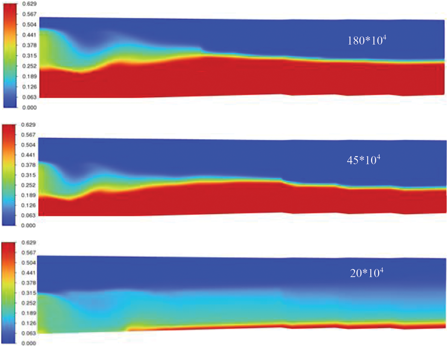
Figure 5: Proppant transportation model in deep coal fracture
The segmentation of the model mesh has a direct impact on the computational speed and accuracy. In this study, the researchers aimed to determine the most suitable number of grids for simulating proppant transport and placement in fractures of a trapezoidal branch joint model with variable fracture width. The simulations were conducted under consistent parameter conditions (refer to Table 2 and Fig. 5). The optimal grid number was identified by comparing the distribution patterns of dunes and suspended zones within the fractures.
With the increase in burial depth, the ground stress rises, leading to higher construction pressure. In complex structural areas, there is a notable increase in fracture pressure and challenges in sand addition [26–29]. In order to effectively address small cracks, secondary cracks, and main cracks, and maximize the volume of effective reconstruction, a combination support ratio of 40/70 mesh:30/50 mesh:20/40 mesh = 1:3:6 is utilized. However, the on-site support effect is inadequate, highlighting the urgent need for in-depth research on coal proppants.
4.1 Optimization of Proppant Combination Based on Diversion Experiment
When ceramic proppant with three particle sizes of 20/40 mesh, 30/50 mesh and 40/70 mesh was mixed in different proportions, its conductivity was tested [30,31] and the sand concentration was 10 kg/m2. The experimental results are shown in Fig. 6. Under the condition of high sand volume and sand ratio, when the closure pressure is lower than 20 MPa, the proppant combination with a larger particle size (40/70 mesh:30/50 mesh:20/40mesh = 6:3:1) exhibits significantly higher conductivity compared to the proppant combination with a larger particle size (40/70 mesh:30/50 mesh:20/40 mesh = 1:3:6) proppant combination, and the larger the proportion of large particle size proppant, the greater its conductivity. However, when the closing pressure exceeds 20 MPa, the disparity in conductivity among each ratio combination gradually diminishes. Under the condition of high closing stress of 40 MPa (see explanation of geological conditions in Part II), 40/70 mesh:30/50 mesh:20/40 mesh = 6:3:1, 5:3:2, 4:3:3. The conductivity of the three types of proppant particle size combinations is 13, 18 and 22 mD·cm, respectively. The difference in the conductivity of the three types of particle size combinations is within 5 mD·cm, and the difference is not large. Support fractures with high conductivity can only be formed near the well. Therefore, it is entirely feasible to blindly pursue increasing the proportion of large-particle size proppant to enhance the supporting effect in deep coal reservoirs and to increase the proportion of small-particle size proppant to improve the migration range of proppant and the spread range of fracturing.
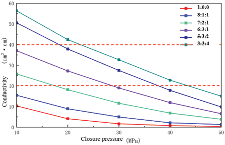
Figure 6: Conductivity of supported fractures under different particle size combinations
4.2 Study on Proppant Transportation Law of Deep Coal Fracture
At present, most studies on proppant migration in coalbed methane Wells are aimed at simulating proppant placement in simple fractures [32–36]. However, due to the high Poisson’s ratio, low Young’s modulus, and the reservoir characteristics of coal bedding and cutting structure development, deep coal-rock reservoirs are not easy to expand outward, and are prone to form complex multi-branch fractures and trapezoid steering fractures near Wells. Simple fracture proppant migration simulation cannot sufficiently explain the proppant placement in deep coal fractures. Therefore, this paper establishes a complex multi-branch fracture model according to the fracture characteristics of deep coal fractures and studies the proppant migration law considering the actual fracture morphology of deep coal fractures, as shown in Fig. 7.
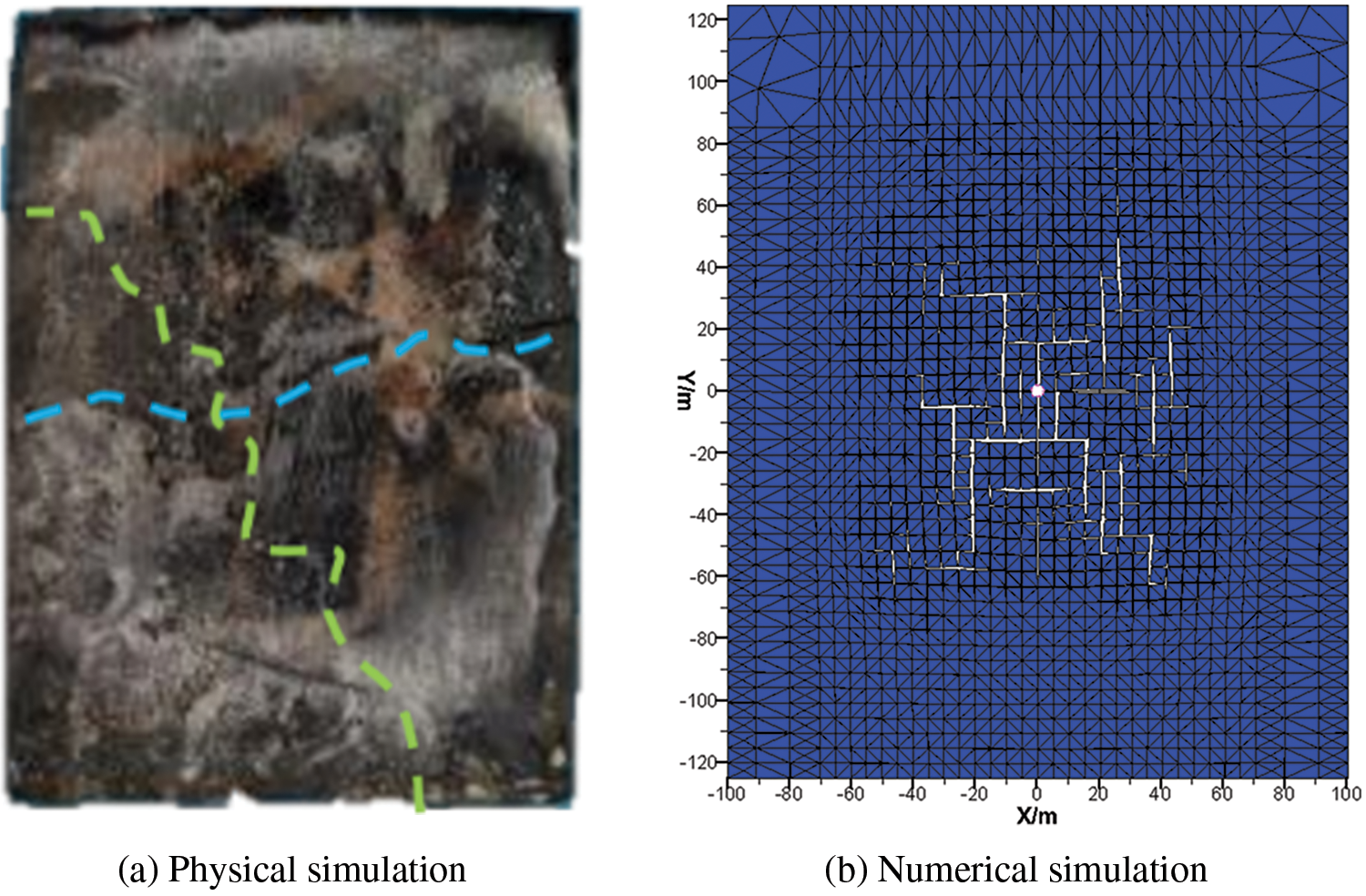
Figure 7: Trapezoidal fracture formed in hydraulic fracturing experiment in deep coal fracture
4.2.1 Fracture Model Verification
The numerical simulation model was verified by the laboratory proppant dynamic sand-carrying experiment. The dynamic sand-carrying experiment [37] adopts a visual window to observe the proppant migration characteristics in the fracture. The size of the experimental model is the same as that of the numerical simulation, and the pumping parameters of 18 m3/min (common discharge rate of deep coal fracture), sand ratio of 15%, fracturing fluid viscosity of 10 m·Pas, and proppant density of 1500 kg/m3 are adopted. The shape of the sand embankment after the two pumping is shown in Fig. 8. It can be obviously observed that the sandbank height and proppant placement pattern after the dynamic sand-carrying experiment are basically consistent with the numerical simulation. Therefore, the numerical simulation model established in this paper can reflect the real intrafracture-proppant migration.

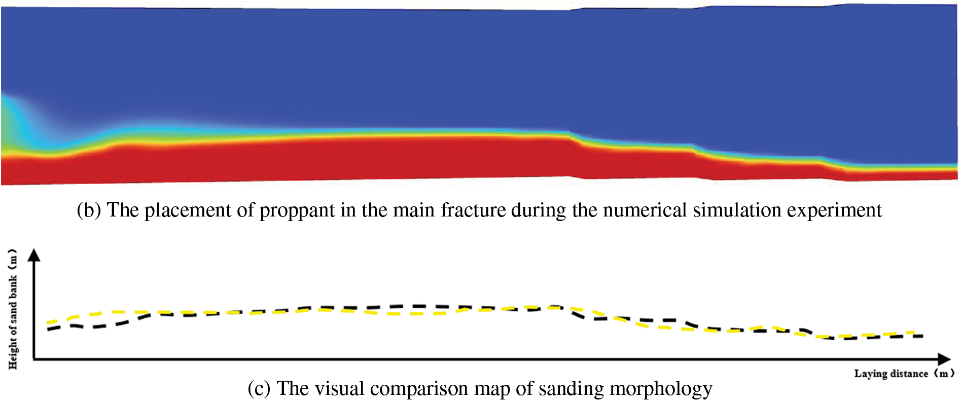
Figure 8: Comparison of proppant placement
4.2.2 Proppant Placement in Complex Fractures with Variable Fracture Width and Multiple Branches
The trapezoidal branch joint model with variable fracture width was established according to the real fracture morphology of deep coal fracture, taking into account the characteristics of high ground stress, high Poisson ratio, low Young’s modulus and obvious change of fracture width in deep coal fracture (Fig. 9), and the fracture width was reduced by 1 mm each turn (the initial branch joint width was 10 mm). The combination of proppant particle size and sand ratio were optimized by considering the proppant placement in complex fractures in deep coal fractures.
As shown in Fig. 9, after the equilibrium of proppant settlement was reached, the transportation of each proppant particle size combination in the complex fracture with variable fracture width and multiple branches was analyzed.
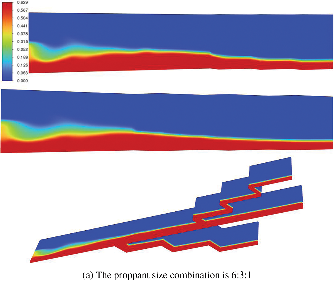
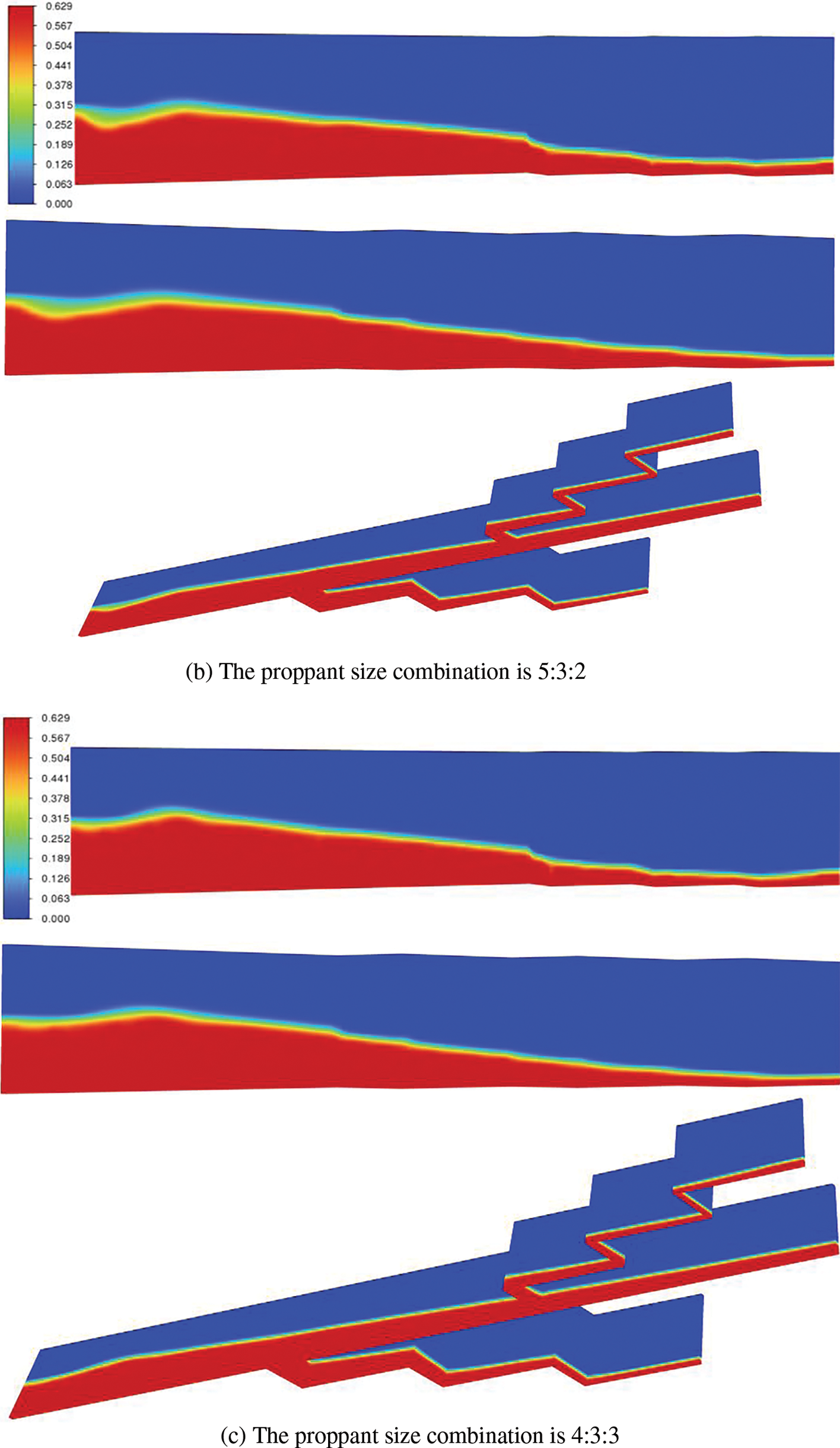
Figure 9: Proppant placement in complex fractures with variable fracture width and multiple branches under different proppant particle size combinations
The migration distance and placement height of proppant gradually increased with the increase of the proportion of proppant in 40/70 mesh. When the proppant size combination is 40/70 mesh:30/50 mesh:20/40 mesh = 6:3:1, the height of the sand dike in the joint of major fracture is 5.65 cm. The height of the sand dike at the connecting point between the main joint and branch joint 1 is 9.82 cm, the height of the sand dike at the connecting point between the main joint and branch joint 2 is 8.80 cm. And simultaneously, the height of the sand dike at the end of the main joint is 8.73 cm. Overall, the height of the sand dike in the main joint shows a trend of first increasing and then decreasing. The height of the sand bank at the end of the fracture increased by 35.3% compared with that at the major fracture. The height of sand bankt tended to be stable after the proppant migration distance exceeded 1 m (at branch fracture 2), and there was no obvious change between branch and major fracture.
After the proppant ratio of 40/70 meshes is reduced to 50%, the height of the sand embankment in the main fracture is 13.31 cm, which the height of the sand embankment at the connecting point between the main fracture and branch fracture 1, branch fracture 2 respectively are 8.57 and 7.94 cm. Under the present circumstances, the height of the sand embankment at the end of the main fracture is 52.7 cm. Compared with the main fracture opening, the fracture end sand embankment height decreased by 60.4%.
Obviously, when the proppant ratio of 40/70 mesh is reduced to 40%, the sand embankment height in the main fracture is 15.84 cm, the sand embankment height at the connecting point between the main fracture and branch fracture 1, branch fracture 2 respectively are 15.63 and 6.18 cm. Under the present circumstances, the sand embankment height at the end of the main fracture is 3.53 cm. Compared with the heel of the main fracture, the sand embankment height at the toe of fracture is reduced by 77.7%. This indicates that for deep coal reservoirs with multiple branch fractures, increasing the proppant ratio of 40/70 mesh can effectively increase the proppant placement area in the branch narrow fractures.
Compared with the sand placement of branch joint 1 and branch joint 2 in the same model, the sand embankment height of branch joint 2 under the combination of three proppant particle sizes decreased to different degrees compared with branch joint 1, among which, the models with 40/70 mesh proppant accounting for 40%, 50% and 60% decreased by 75.4%, 68% and 20.4%, respectively. It can be obviously seen that when the proppant proportion of 40/70 mesh reaches 60%, the proppant placement height in 5 mm narrow fractures (branch fractures 2, the narrowest fracture width is 2 mm) increases significantly, and the sand embankment height difference between main fractures and branch fractures is minimal. This indicates that for complex fractures in deep coal and rock reservoirs with narrow fracture widths, the fracture width is small.
In addition, with the propagation of the toe of fractures to the remote, the proppant distribution gradually changes from multi-layer to single-layer. Due to the small width of the toe of the fracture, the proppant can’t be filled in the fracture. However, only a small amount of proppant can not prop the fracture, and the fracture opening is reduced or even closed [38]. Considering the characteristics of a high Poisson ratio and low Young’s modulus in deep coal fractures, proppant embedment is more likely to happen in coal, in which the small proppant sand placement concentration at branch fractures and the toe of fracture are not enough to prop. Due to the significant improvement of proppant placement in branch fractures, increasing the ratio of 40/70 mesh proppant can reduce the risk of sand plugging. This indicates that for deep coal reservoirs when the ratio of 40/70 net proppant is greater than 60%, the sand placement concentration in branch narrow fractures can be increased, which is conducive to realizing the full-scale propping of fractures.
4.2.3 Optimization of Proppant Sand Ratio in Multi-Stage Fracturing of Horizontal Wells
The influence of different sand ratios on proppant placement (see Fig. 10): When the sand ratio is 10%, the placement area of proppant in the fracture and the effective propping fracture length are smaller; As the sand ratio increases from 10% to 20%, the proppant placement area in the fracture and the effective propping fracture length gradually increase. The sand ratio has more influence on the equilibrium height and the distance between the front of the sand bank and the fracture entrance.
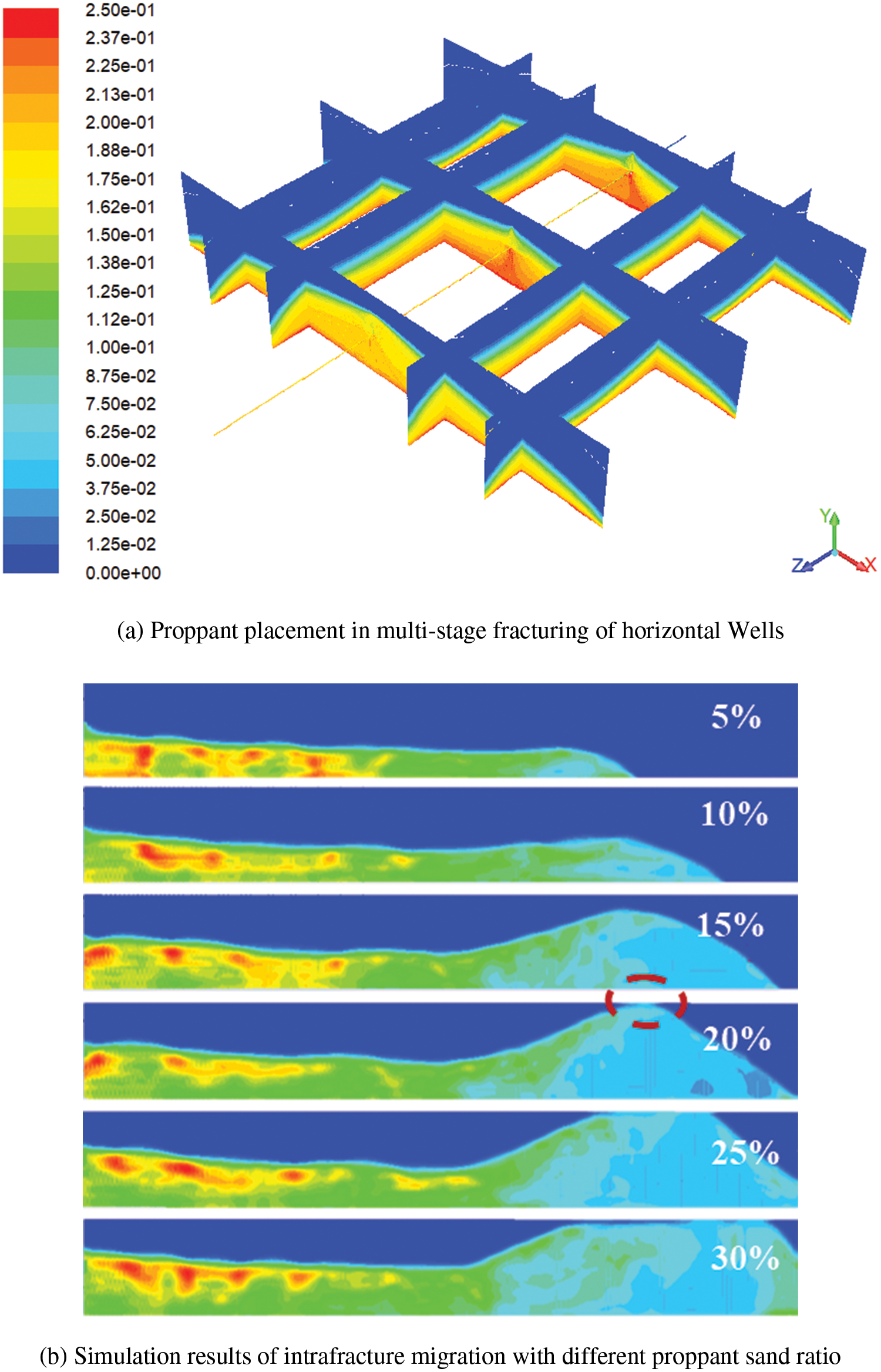
Figure 10: Morphology of sand embankment in fractures under different sand ratios
The reason for this is that with the increase of the sand ratio in the sand carrier fluid, the sand concentration in the same volume of the sand carrier fluid increases, resulting in a clustering phenomenon between proppants, thereby speeding up the proppant deposition rate, so as the sand ratio increases, the equilibrium time will become smaller. When the fracture width is 5 mm, the higher sand ratio is more likely to cause proppant accumulation in the front end of the fracture, resulting in sand blockage. When the sand ratio is 15%, the proppant transportation distance in the secondary fracture reaches the maximum value. If the sand ratio continues to increase, the proppant sand filling area in the secondary fracture depth can only be increased.
In order to study the influencing factors of proppant transportation in deep coal fractures, the numerical simulation results of proppant transportation were successfully applied to 15 CBM test Wells in Linxing-Shenfu block of Ordos Basin. 15 Wells are located in the same coal mining face, buried more than 1700 m, and are only fractured for 8 + 9# coal fracture. 8 + 9# coal fracture is black bright coal, 8 + 9# reservoir thickness is 8–10 m, average 8 m, primary structural coal, direct roof is mainly mudstone, local sandstone development, all using active water and clean fracturing fluid, construction pumping-rate of 12–18 m3/min, 40/70, 30/50, 20/40 head combination quartz sand proppant. Through the gradual optimization of construction parameters, the multi-particle size combination of test Wells before 2021 is mainly 40/70 mesh or 30/50 mesh, and the construction pumping-rate is 6–10 m3/min. Most production Wells have problems such as low coalbed methane production, rapid gas production decline, high water production and limited effective support fracture size, etc., and the production is generally low. Among them, test well 4 has the highest gas production due to coal fractures 4 + 5# and 8 + 9#, and the production of the other 5 test Wells is generally lower than 1000 m3/d, as shown in Fig. 10.
In 2022, the proppant combination of 40/70, 30/50 and 20/40 mesh is adopted, and the construction pumping-rate is 12–18 m3/min. The ratio of medium diameter proppant in 30/50 mesh is attempted to reduce, and the ratio of large diameter proppant in 20/40 mesh and small diameter proppant in 40/70 mesh is increased. A proppant combination ratio of 40/70/30/50:20/40 = 6:3:1 is generally used. The pumping-rate increased to 12–18 m3/min, the strength of sand addition increased to 12–27 m3/m, and the strength of liquid used increased to 115–285 m3/m. The optimization effect was obvious, which the production of coal gas Wells in Linxing-Shenfu block achieved a stable gas production breakthrough of 2000–12000 m3/d. In addition to the relatively poor production of LX-38 well, the overall production capacity has improved significantly, as shown in Fig. 11.
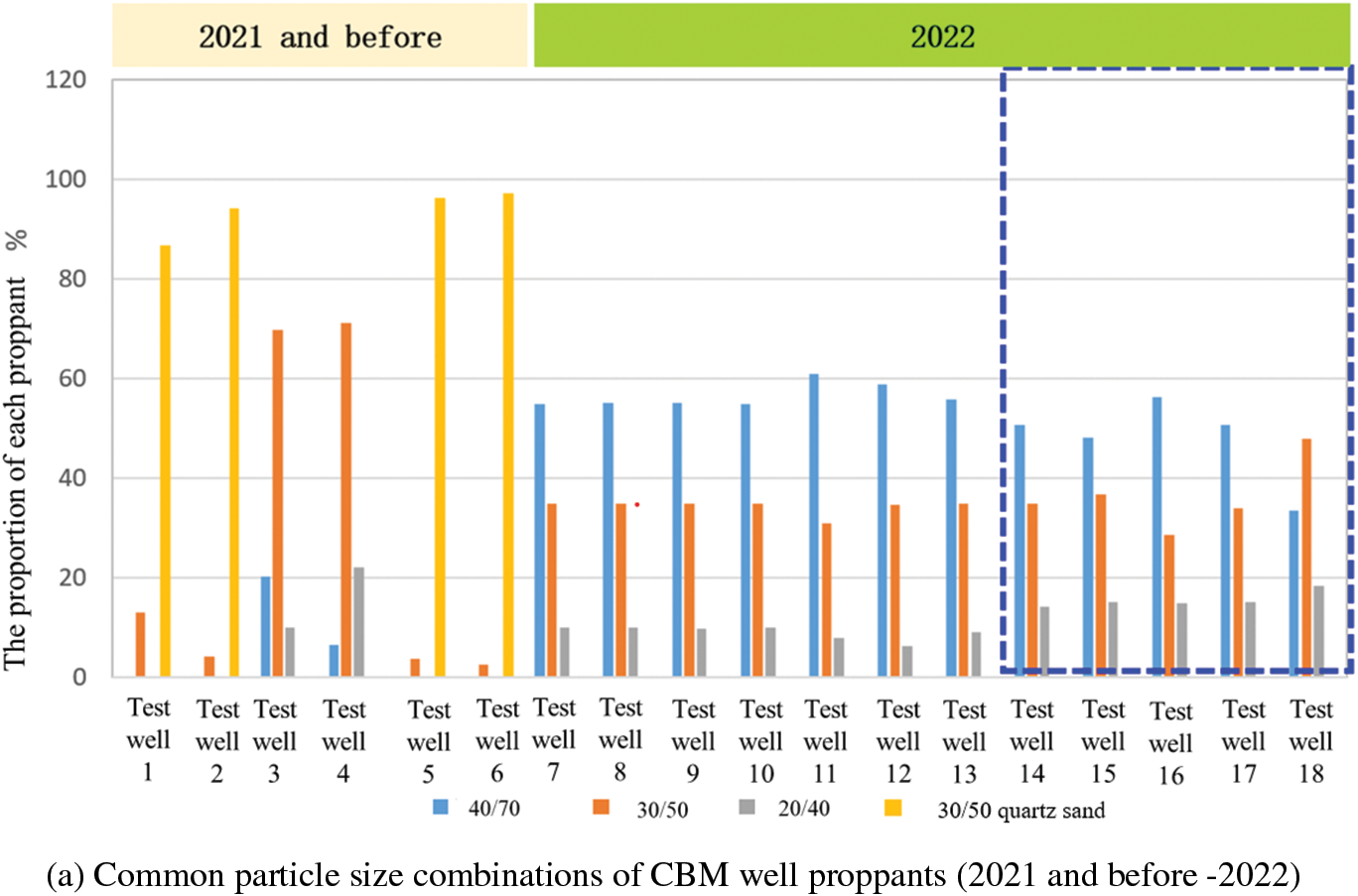
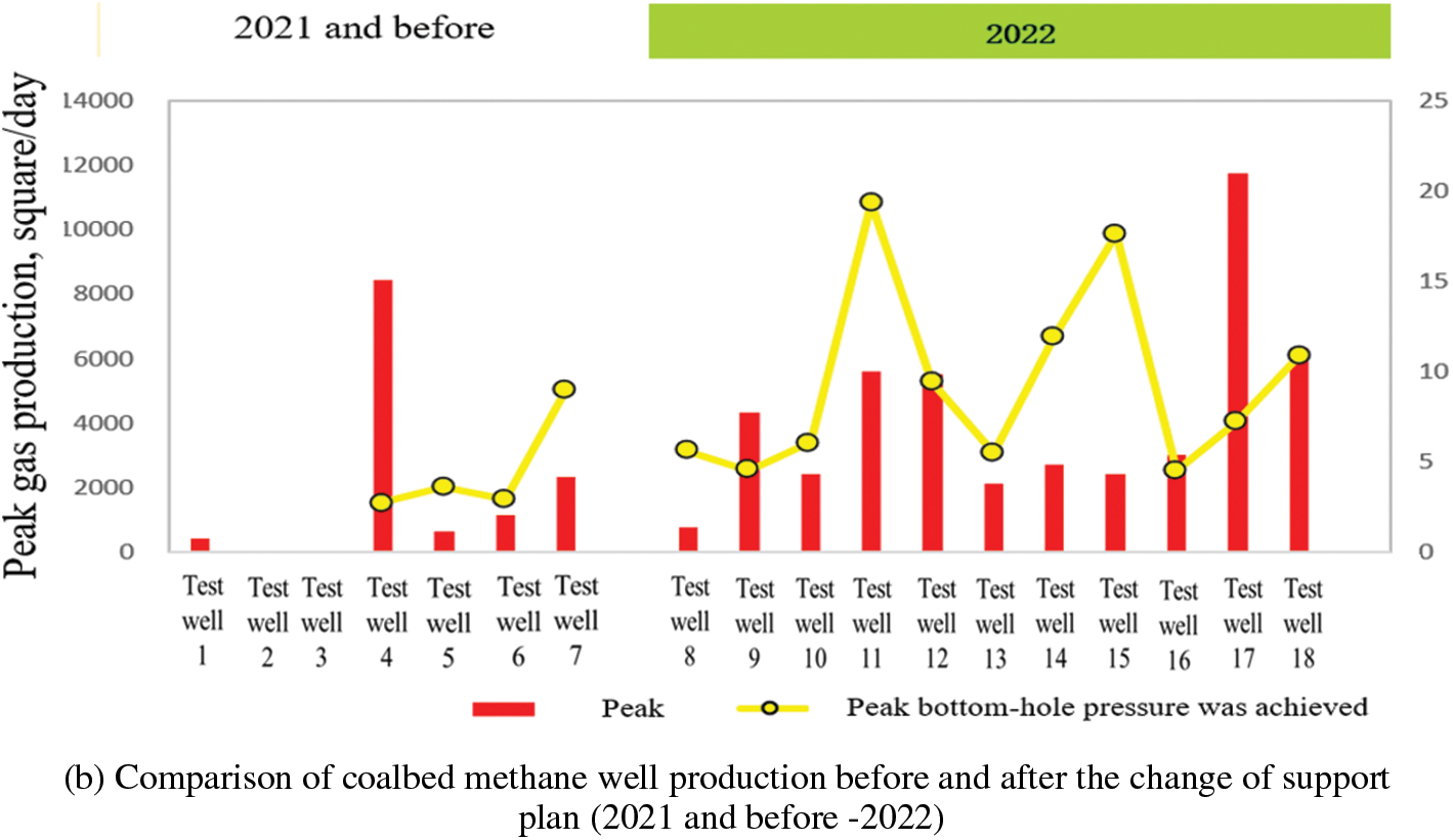
Figure 11: Morphology of sand embankment in fractures under different sand ratios
The effect of proppant placement in deep seam is mainly affected by fracture width, proppant particle size and particle size combination, etc. The proppant combination scheme with small particle size and large proportion is conducive to filling branch fractures at all levels and realizing full-scale fracture support. Specific conclusions are as follows:
(1) Increasing the sand concentration can greatly improve the conductivity, and the sand concentration should be increased correspondingly with the increase of formation closing pressure, which is more necessary in soft coal fractures.
(2) In the process of fracturing construction, considering the effect of fracture-making and sand carrying, the application of small particle size proppant (20/40 mesh) in the early stage and low pumping-rate construction can better support the branch fracture system of multiple fractures and make the fracture extend longer; Follow-up of larger diameter proppant (10/20 mesh) improves near-wellbore conductivity.
(3) Considering that the proppant mainly fills the main fracture, the placement range of the branch fracture is mainly determined by the placement width of the branch fracture at the main fracture, and the placement volume of the secondary proppant in the parallel main fracture at the far end of the perforation cluster is larger. When the sand ratio of 15%, the proppant transportation distance in the secondary fracture reaches the maximum, and the continued increase of the sand ratio can only increase the proppant sand filling area in the secondary fracture depth.
(4) Small particle size and low density (40/70 mesh) mainly at the distal end of the main fracture or branch fracture, and conventional density large particle size proppant mainly settled near the fracture; With the increase of the proportion of small and medium particle size (30/50 mesh, 40/70 mesh), the sand concentration in the main joint decreases, and the sand concentration in the secondary joint increases gradually.
(5) The transportation distance of proppant increases with the increase of sand volume and the decrease of particle size, and the optimal single cluster sand volume is 50–60 m3; The particle size combination can make up for the shortcomings of small particle size sand placement concentration and small longitudinal placement range of large particle size, and the main sand injection in the branch fracture is 40/70 mesh proppant (the same as the proppant transportation law in the field), and the proportion of 40/70 mesh proppant should be considered in the production according to the actual complexity of artificial fractures.
(6) The optimization results of the on-site support scheme are highly consistent with the conclusions obtained from the numerical simulation results, which means that in deep coal seams, it is not necessary to blindly increase the proppant particle size to improve the fracture conductivity in the near-wellbore area, but to optimize the proppant pumping scheme by considering the complex fracture network formed by hydraulic fracturing in deep coal seams. The proportion of proppant with small particle size (≥60%) can precisely meet the demand of proppant migration under complex fracture conditions in deep coal seams, and can obtain the best proppant placement area and distance.
Acknowledgement: None.
Funding Statement: Specific grant number KJGG2022-1002; YF; Key Technologies for Exploration and Development of Onshore Unconventional Natural Gas in CNOOC’s “14th Five-Year Plan” Major Science and Technology Project.
Author Contributions: The authors confirm contribution to the paper as follows: study conception and design: Fan Yang, data collection: Jian Wu, analysis and interpretation of results: Honggang Mi, draft manuscript preparation: Qi Yang. All authors reviewed the results and approved the final version of the manuscript.
Availability of Data and Materials: The data presented in this study are available on request from the corresponding author. The data are not publicly available due to some data and materials originate from the oilfield site and are required to be kept confidential in accordance with local laws and regulations.
Conflicts of Interest: The authors declare that they have no conflicts of interest to report regarding the present study.
References
1. Guo GS, Liu YH, Lv YM. Exploration and development prospects of deep coalbed methane in China. Clean Coal Technology. 2015;21(1):125–8. [Google Scholar]
2. Liu JF, Chun G, Yang DD. Policy and prospect of CBM exploration and development in China. China Economic & Trade Guide (Theor Ed). 2017;867(20):27–9 (In Chinese). [Google Scholar]
3. Kurlenya MV, Serdyukov SV, Patutin AV, Shilova TV. Stimulation of underground degassing in coal seams by hydraulic fracturing method. J Min Sci. 2017;53:975–80. doi:10.1134/S106273911706303X. [Google Scholar] [CrossRef]
4. Msalli AA, Jennifer L, Miskimins. Slickwater proppant transport in complex fractures: new experimental findings & scalable correlation. In: SPE Annual Technical Conference and Exhibition, 2015 Mar; Houston, TX, USA. doi:10.2118/174828-MS. [Google Scholar] [CrossRef]
5. Brannon HD, Malone MR, Rickards AR, Wood WD, Edgeman JR, Bryant JL. Maximizing fracture conductivity with proppant partial monolayers: theoretical curiosity or highly productive reality? In: SPE Annual Technical Conference and Exhibition, 2004 Sep; Houston, TX, USA. doi:10.2118/90698-MS. [Google Scholar] [CrossRef]
6. Chang O, Dilmore R, Wang JY. Model development of proppant transport through hydraulic fracture network and parametric study. J Pet Sci Eng. 2016;150(10):223–4. doi:10.1016/j.petrol.2016.12.003. [Google Scholar] [CrossRef]
7. Li XG, Shu ZK, Zhang P, Yang ZZ. Coal fracture pressure cracks within the proppant transport physics simulation. China: J Reserv Eval Dev. 2020;10(4):39–44+52 (In Chinese). [Google Scholar]
8. Song LL. Experimental study on the conductivity of coal rock fracture and analysis of its influencing factors. Liaoning Chem Ind. 2017;46(8):782–4+803 (In Chinese). [Google Scholar]
9. Zhang HJ, Wang YY. Factors affecting CBM reservoir complex fracture diverting capacity study. J Coal Mine Saf. 2022;5:21–6 (In Chinese). [Google Scholar]
10. Khanna A, Kotousov A, Sobey J, Weller P. Conductivity of narrow fractures filled with a proppant monolayer. J Pet Sci Eng. 2012;100:9–13. [Google Scholar]
11. Zhang LY, Qu ZQ, Lv MK, Guo TK, Liu XQ, Wang XD. Different proppant, and the effects of combination of complex propping fracture. J Fault Block Oil Gas Fields. 2021;28(2):278–83 (In Chinese). [Google Scholar]
12. Wang L, Zhang SC, Zhang WZ, Wen QZ. Experimental study on long-term conductivity of proppant combinations with different particle sizes in composite fracturing. Nat Gas Ind. 2005;(09):64–6+155–6 (In Chinese). [Google Scholar]
13. Zou YS, Ma XF, Wang L, Lin X. Experimental evaluation of conductivity of fracturing in medium and high-rank coal beds. J China Coal Soc. 2011;36(3):473 (In Chinese). [Google Scholar]
14. Yang SY, Yang XJ, Yan XZ, Xu JG, Fan H. Variable density proppant migration of coal-bed methane hydraulic pressure crack law. J Coal. 2014;33(12):2459–65. [Google Scholar]
15. Keshavarz A, Mobbs K, Khanna A, Bedrikovetsky P. Stress-based mathematical model for graded proppant injection in coal bed methane reservoirs. Appea J. 2013;53:337–46. [Google Scholar]
16. Zou YS, Shi SZ, Zhang SC, Yu TX, Tian G, Ma XF, et al. Experimental study on sand fracturing and fracture conductivity of tight conglomerate: a case study of Mahu tight conglomerate in Junggar Basin. Pet Explor Dev. 2021;48(6):1202–9 (In Chinese). [Google Scholar]
17. Zou YS, Zhang SC, Zhang J, Wang X, Lu HB. Pulverized coal on the damage mechanism of fracture diverting capacity. J Coal. 2012;(11):1890–4 (In Chinese). [Google Scholar]
18. Tsang YW. The effect of tortuosity on fluid flow through a single fracture. Water Resour Res. 1984;20(9):1209–15. doi:10.1029/WR020i009p01209. [Google Scholar] [CrossRef]
19. Wan L, Chen M, Zhang F, Wang L, Chen W. Numerical simulation and experimental study of near-wellbore fracture initiation mechanism on sandstone coal interbedding. In: International Petroleum Technology Conference, 2019 Mar; Beijing, China. IPTC-19356-MS. doi:10.2523/IPTC-19356-MS. [Google Scholar] [CrossRef]
20. Abubakar I, Moaz H, Khaled AA, Murtada SA, Mohamed M. A comprehensive review of proppant transport in fractured reservoirs: exper imental, numerical, and field aspects. J Nat Gas Sci Eng. 2021;88:103832. doi:10.1016/j.jngse.2021.103832. [Google Scholar] [CrossRef]
21. Sahai R, Miskimins JL, Olson KE. Laboratory results of proppant transport in complex fracture systems. In: Presented at the SPE Hydraulic Fracturing Technology Conference, 2014 Feb 4–6; Woodlands, TX, USA. SPE-168579-MS. doi:10.2118/168579-MS. [Google Scholar] [CrossRef]
22. Kranzz RL, Frankel AD, Engelder T, Scholz CH. The permeability of whole and jointed barre granite. Int J Rock Mech Min Sci Geomech Abstr. 1979;16(4):225–34. doi:10.1016/0148-9062(79)91197-5. [Google Scholar] [CrossRef]
23. Guo TK, Gong YZ, Liu XQ, Liu XJ, Wang ST, Wang F. Numerical simulation of proppant migration and placement in complex fractures. J China Univ Pet (Ed Nat Sci). 2022;46(3):89–95 (In Chinese). [Google Scholar]
24. Fredd CN, McConnell SB, Boney CL, England KW. Experimental study of hydraulic fracture conductivity demonstrates the benefits of using proppants. In: SPE Rocky Mountain Regional/Low Conductivity Reservoirs Symposium, 2000 Mar 12–15; Denver, CO, USA. SPE-60326-MS. doi:10.2118/60326-MS. [Google Scholar] [CrossRef]
25. Wen QZ, Gao JJ, Liu H, Liu XJ, Wang ST, Wang F. Dynamic experiment on slick-water prop-carrying capacity. Oil Drill Prod Technol. 2015;37(2):97–100 (In Chinese). [Google Scholar]
26. Babcock RE, Prokop CL, Kehle RO. Distribution of propping agents in vertical fractures. In: API Production Division Mid-Continent District Meeting. 1967 Mar 29; Oklahoma City, OK, USA. vol. 851-41-A. [Google Scholar]
27. Raki S, Moghanloo RG. Proppant transport in complex fracture networks—a review. J Pet Sci Eng. 2019;182:106199. doi:10.1016/j.petrol.2019.106199. [Google Scholar] [CrossRef]
28. Barton N, Bandis S, Bakhtar K. Strength, deformation and conductivity coupling of rock joints. Int J Rock Mech Min Sci Geomech Abstr. 1985;22(3):121–40. doi:10.1016/0148-9062(85)93227-9. [Google Scholar] [CrossRef]
29. Chun T, Li Y, Wu K. Comprehensive experimental study of proppant transport in an inclined fracture. J Pet Sci Eng. 2020;184:106523. doi:10.1016/j.petrol.2019.106523. [Google Scholar] [CrossRef]
30. Ribeiro LH, Sharma MM. A new three-dimensional, compositional, model for hydraulic fracturing with energized fluids. In: SPE Annual Technical Conference and Exhibition, 2012 Oct 8–10; San Antonio, TX, USA. SPE-159812-MS. doi:10.2118/159812-MS. [Google Scholar] [CrossRef]
31. Novotny EJ. Proppant transport. In: SPE 52nd Annual Fall Technical Conference and Exhibition, 1977 Oct 9–12; Denver, CO, USA. SPE-6813-MS. doi:10.2118/6813-MS. [Google Scholar] [CrossRef]
32. Terracina JM, Turner JM, Collins DH, Spillars SE. Proppant selection and its effect on the results of fracturing treatments performed in shale formations. In: SPE Annual Technical Conference and Exhibition, 2010 Sep 19–22; Florence, Italy. SPE-135502-MS. doi:10.2118/135502-MS. [Google Scholar] [CrossRef]
33. Gong X, Wang Y, Han W, Wu X, Li J, Zhang H. Characteristics and fracturing parameters optimization of coal reservoin near normal fanhtacase study of Shizhuang South Block. Fault-Block Oil Gas Field. 2021;28(4):514–8 (In Chinese). [Google Scholar]
34. Guo TK, Qu ZQ, Li MZ, Chen DC, Dong CY, Wang WY. Development of a virtual simulation device for proppant transport of large and complex fractures. Lab Res Explor. 2018;37(10):242–6 (In Chinese). [Google Scholar]
35. Kern LR, Perkins TK, Wyant RE. The mechanics of sand movement in fracturing. In: Annual Fall Meeting of Society of Petroleum Engineers, 1959 Oct 5–8; Houston, TX, USA. SPE-1108-G. doi:10.2118/1108-G. [Google Scholar] [CrossRef]
36. Penny GS. An evaluation of the effects of environmental conditions and fracturing fluid upon the long-term conductivity of proppants. In: Presented at the SPE 62nd Annual Technical Conference and Exhibition, 1987 Sep 27–30; Dallas, TX, USA. SPE-16900-MS. doi:10.2118/16900-MS. [Google Scholar] [CrossRef]
37. Elimelech M, Gregory J, Jia X, Williams R. Particle deposition and aggregation: measurement, modelling, and simulation. New York, USA: Butterworth-Heinemann; 1995. [Google Scholar]
38. Guo T, Luo Z, Mou S, Chen M, Gong Y, Qin J. Numerical simulation of proppant dynamics in a rough inclined fracture. Fluid Dyn Mat Process. 2022;18(2):431–47. doi:10.32604/fdmp.2022.017861. [Google Scholar] [CrossRef]
Cite This Article
 Copyright © 2024 The Author(s). Published by Tech Science Press.
This work is licensed under a Creative Commons Attribution 4.0 International License , which permits unrestricted use, distribution, and reproduction in any medium, provided the original work is properly cited.


 Submit a Paper
 Propose a Special lssue
 View Full Text
 Download PDF
 Downloads
 Citation Tools