
 Submit a Paper
 Propose a Special lssue
 Open Access
ARTICLE

Numerical Simulation of the Mechanical Stirring Process in a Tannin-Based Foaming Precursor Resin
1 Yunnan Provincial Key Laboratory of Wood Adhesives and Glued Products, Southwest Forestry University, Kunming, 650224, China
2 Department of Polymers and Pigments, National Research Centre, Cairo, 12622, Egypt
3 Key Laboratory for Forest Resources Conservation and Utilization in the Southwest Mountains of China, Southwest Forestry University, Kunming, 650224, China
* Corresponding Authors: Xiaojian Zhou. Email: ; Xinyi Chen. Email:
Fluid Dynamics & Materials Processing 2024, 20(10), 2219-2234. https://doi.org/10.32604/fdmp.2024.052445
Received 01 April 2024; Accepted 27 May 2024; Issue published 23 September 2024
 View Full Text
 Download PDF
Abstract
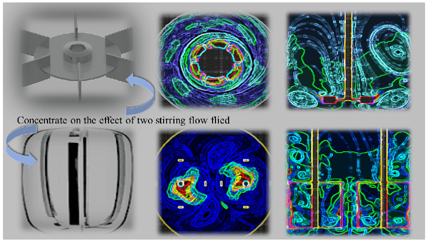
Tannin foam is a new functional material. It can be widely applied to the automobile industry, construction industry, and packaging industry due to its wide range of raw materials, renewable, easily degraded, low cost and almost no pollution. Preparing tannin foam is a very complex process that includes high temperature, two phases, mechanical agitation, and phase change. To investigate the influence of the stirring velocity and paddle shape, simulation was calculated by making use of the volume of fluid (VOF) method and multiple reference frame (MRF) method in a three-dimensional flow field of tannin-based foaming precursor resin. The gas holdup and velocity magnitude were analysed with various conditions of mechanical velocities and paddle shape in the stirring flow field. The result shows the higher the velocity, the greater the disturbance and paddle shape between the eggbeater and the Rushton turbine, obviously the paddle shape of the eggbeater with a wider range of agitation, which can entrap more air into the tannin-based foaming precursor resin in a short time. Especially when the speed is 1500 rpm, the flow field of the Rushton turbine comes out of a ditch, which decreases the efficiency of mass transfer; there is less air to mix into the tannin-based foaming precursor resin, which causes unevenness. At the same time, the eggbeater shows the marvelous capability of hybrid as it has two vortexes and multiple cycles that make a difference from the Rushton turbine, which has only one vortex and two upper and lower loops; the structure makes the flow field more stable allowed evenness of flow field tannin-based foaming precursor resin. The results reveal that it is beneficial for tannin-based foaming precursor resin to use an eggbeater with a speed of 1500 rpm to reduce the consumption of resources while obtaining a uniform flow field.Graphic Abstract
Keywords
Foams with excellent properties, such as light weight, thermal insulation, and flame retardancy, have been prepared from tannin material [1–5]. At present, a series of efforts have focused on its preparation and modification, with the aim of designing and fabricating tannin-based foams with outstanding overall performance. Among those preparation methods, mechanical stirring foaming is considered a promising green way to perform this task, which allows avoidance of foaming agent application; obviously, this approach imposes a lesser burden on the environment.
The process of mechanical stirring is vital to foam structure and performance, but most of the literature on the foaming process is based on metal foam, and there is a lack of research on the foaming process of tannin-based foam. There has been much research investigating the properties of formed tannin-based foams in recent years, but few studies have analysed the foaming process, which presents a large challenge for obtaining relative experimental parameters [6–9]. To investigate the effect of the mechanical stirring process on tannin-based foam, the present work was carried out. During the foaming process, factors such as the mechanical stirring velocity, the shape of the agitator, the physical properties of the solution, the temperature of the environment and the duration of stirring all have crucial impacts on the whole foaming process. In addition, studies of stirred vessel flows are complex, and many factors arise in the process of mechanical stirring [10–13].
In the past few decades, most of the research on stirred flow has adopted numerical simulation methods. Many studies have focused on the stirring flow field, and most of these studies focused on the geometry, Reynolds number, power number, bubble distribution and rotation speed [14–17]. It seems that the flow field is affected by many factors, so it is vital to investigate the effect on the foaming process to improve the flow field. Mechanical stirring involves not only mixing the contents but also mixing the air, which proves that the foaming process is a part of fluid mechanics. This work explores the foaming process of tannin foam [13], which is prepared without a foaming agent based on mechanical agitation in physical foaming, and through the experience of foam preparation in the laboratory, the mechanical stirring velocity and shape of the agitator have a great influence on the foaming process. Under the working conditions of two-phase flow, the improved mixing and speed increase cause the vortex to occur at the same time and space, leading to the production of more small-scale structures, compression of the other spatial structures of the vortex structure, and an increase in the energy cascade effect; thus, the comprehensive performance under high speed and scope of work is better than that under lower speed, but at the same time, the gas phase can more easily accumulate at a lower rotational speed, and literature studies have also proven that the mechanical rotational speed and impeller type have significant effects on the structure of the flow field [18,19]. On this basis, both the velocity and paddle shape are selected as indexes to investigate the effect on the flow field, which is beneficial for improving the foaming process via mechanical stirring. There are some relationships among the rotation speed, the paddle shape and the stirring effect, and it has been concluded that as the rotation speed increases, the energy cost decreases [20]. Many paddle shapes, including the Rushton turbine, perturbed six-bent-bladed turbine, anchor-type, squire type, disc impeller, etc., were simulated to investigate the effect on the flow field, and the Rushton turbine has received much attention [21–24].
With the development of computational fluid dynamics (CFD) techniques and multiple reference frame (MRF) methods, it has become possible to simulate the foaming process by mechanical stirring. In this study, numerical simulation was used to simulate the mechanical stirring-induced foaming process, and the influence of stirring speed and paddle shape on this process was considered. With respect to the simulation of stirring impellers, there are two classical methods, multiple reference frames and moving meshes; the former fit complex working conditions, but the latter fit the unsteady process of changing the flow field. The MRF method is a mature technology that has been extensively utilized in rotation areas [25]. The interface between the rotation domain and container made use of changing the velocity and mass to mix the entire region. The selection of the interface is usually accomplished in the range of 1/8–1/4 (the value is the interface with the distance of the container). This approach is suitable for the simulation environment for the experimental range. Through numerical simulation of the foaming process, the motion characteristics, distribution characteristics and various parameters of bubbles can be more accurately determined to obtain better foaming materials. Therefore, the use of numerical simulations to study the tannin foaming process will be the focus of future research.
This study considered the transformation of the flow field caused by changes in the velocity and shape of the paddle in the rotor area of the stirrer beaker, which is also called the rotation domain. To simplify the calculation process, the stirrer beaker is assumed to be a cylinder, which has a standard Rushton impeller of six blades, as shown in Fig. 1a. The diameter of the cylindrical beaker is T = 120 mm, and the height is H = 150 mm. The blade diameter is D = 45.3 mm, the blade width and height are w = T/4 and h = T/5, respectively, the blade thickness is d = 1 mm, and the impellers are 15 mm from the bottom. And the mesh structures of the working conditions used in this work is shown in Fig. 1b. To investigate the influence of the paddle shape on the flow field, the eggbeater model was established and calculated via the same procedure as for the Rushton turbine, and the size of the eggbeater was the same scale used in the laboratory. The geometry of the eggbeater is illustrated in Fig. 2a. It has two rotation centers, each of which has the same structure as the impellers, and the data were measured in the laboratory by vernier callipers. The impeller width was m = 47.4 mm, the length was z = 36 mm, and the height was x = 60 mm. And the mesh structures of the working conditions used in this work is shown in Fig. 2b.
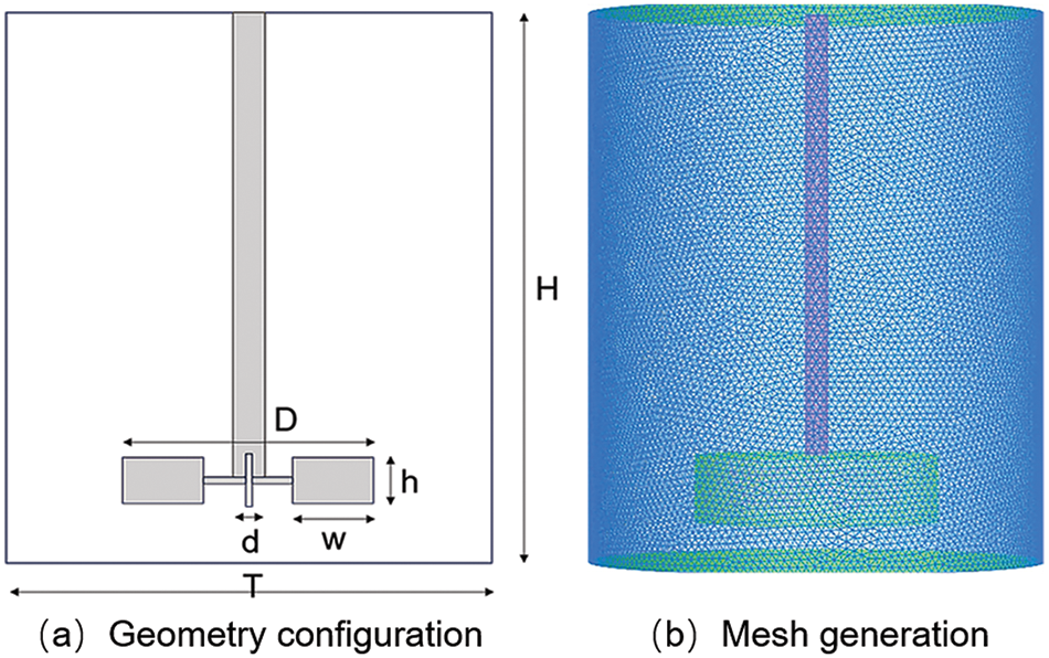
Figure 1: The geometry and mesh of the Rushton turbine
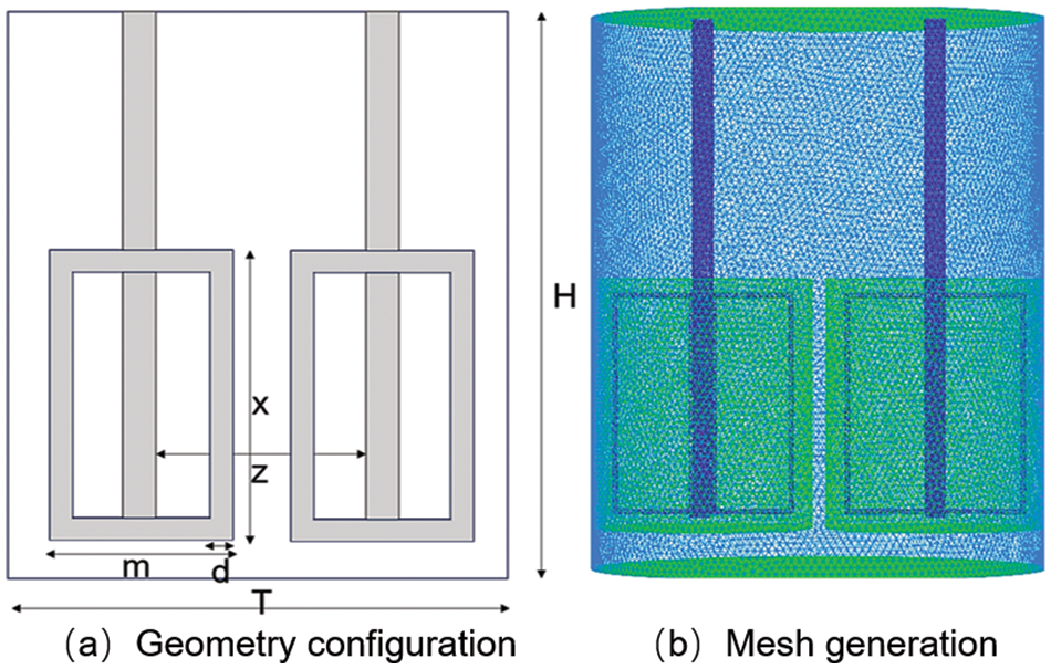
Figure 2: The geometry and mesh of the egg beater
3 The Flow Pattern in the Beaker
The tannin-based foaming precursor resin was used to simulate the experimental environment, and the pattern of the flow field can be calculated by the stirring Reynolds number according to the equation below:
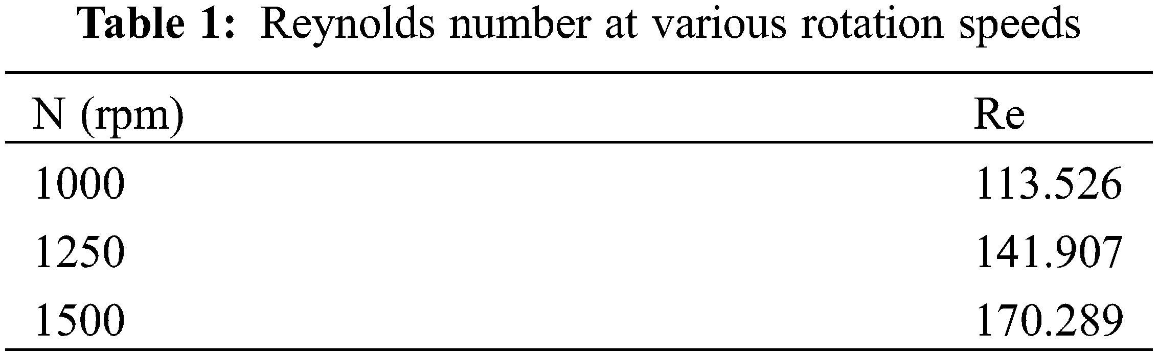
In the equation, Re is a dimensionless number that can be used to characterize the flow of a fluid, ρ is the density of the tannin-based foaming precursor resin, ρ = 1421.667 kg/m3, N is the rotational speed, and there are three speeds in the simulation, as demonstrated in the Table 1. D is the diameter of the impeller, D = 45.3 mm, μ is the dynamic viscosity of the tannin-based foaming precursor resin, and μ = 0.4283 Pa∙s. In this work, there were three kinds of rotational speeds, and the relative Reynolds number was calculated as given in Table 1, where the results show that the flow pattern is laminar.
There are several assumptions that were used to establish the mathematical model. (1) Without regard to the change in energy, (2) the effect of the fluctuation of the tannin resin surface on the initial parameters was ignored. Based on the assumptions above, the laminar flow model is a mathematical model used to simulate the motion of a bubble.
4.1 Governing Dimensional Equations
In the stirring beaker, both the bubble and the tannin resin govern the conservation of mass, momentum, and energy; however, the effects on the flow field of the mechanical velocity and paddle shape were mainly discussed, so the energy conversion was not considered. The governing equations are as follows:
Continuity equations:
Momentum equations:
In the equation, F is the interfacial force of a two-phase fluid,
The VOF model simulates two or more kinds of immiscible fluids by solving a single momentum equation and tracking the volume fraction of the single-phase fluid in the region, which helps accurately track the movement changes of the gas–liquid phase interface. In this simulation, the phase transition process is not considered, and its governing equation is as follows:
Continuity equations:
In the equation,
In this study, the multiple reference frame method (MRF) was used to simulate the four-blade impeller. The steady-state approximation is used for each region with different rotation or moving speeds, and the multiple reference frame model (MRF) is more suitable for the boundary of the grid region, assuming that each cell moves at a uniform speed.
The calculation region is divided into several subregions by a multireference model, and the governing equations of each subregion are determined, in which each subregion moves differently. The transfer and exchange of the flow field structure information at the interface of each subdomain is realized by changing the velocity. In the numerical calculation, the rotor of the rotating reference frame is given a fixed angular velocity as the power source. Using the velocity and velocity gradient fluctuations, the transformation from the motion reference frame to the absolute reference frame can be verified. The transformation formula is as follows:
where
The relative velocity in a moving reference frame can be converted to a value in a stationary reference frame via Eq. (7):
where
Based on the relative velocity, the vector gradient of the absolute velocity is obtained:
4.4 Validation of the Mathematical Model
To verify the simulation, the work was completed under the same simulation conditions reported in the literature [26], and the variation in the power number vs. the Reynolds number is displayed in Fig. 3. The qualitative comparison between the simulation results and experimental results in the same calculation domain showed good agreement with the literature results, indicating that the results of the numerical simulation are reliable.
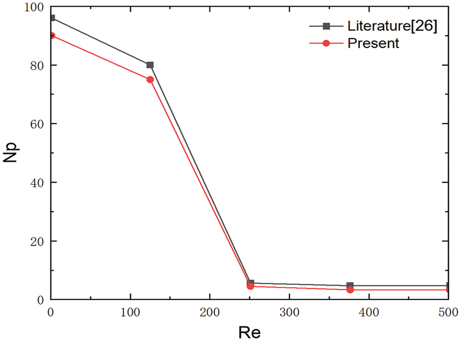
Figure 3: Impeller power vs. the Reynolds number
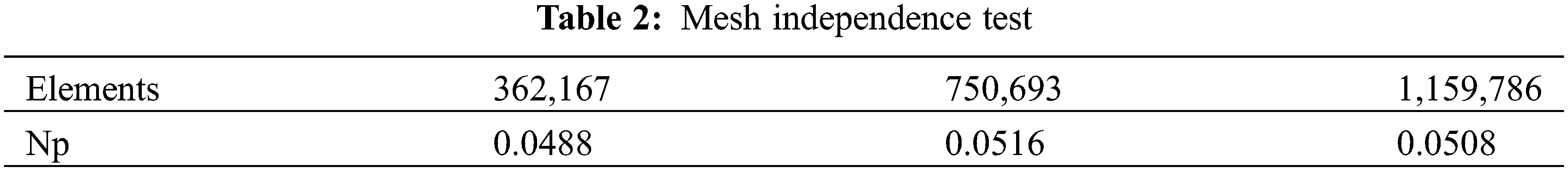
The commercial software FLUENT 2022R1 is used to simulate the gas–liquid two-phase flow in tannin resin to determine the influence of the mechanical agitation speed and paddle shape by solving the governing equations of the VOF model and laminar model. The simulation solution method is based on finite volume discretization. Postprocessing was performed with a TECPLOT360. The solver type is pressure based, and time is defined as transient. The coupling of pressure and velocity is implemented by the SIMPLE algorithm. The momentum is second-order upwind, and the discrete format of the volume fraction is first-order implicit. Due to the complex structure of the mixing stirrer beaker, tetrahedral unstructured mesh with strong spatial adaptability was used to mesh the fluid in the stirrer beaker. A preprocessor (ANSYS Meshing) was used to discretize the flow domain with an unstructured tetrahedral mesh. A mesh test was performed to ensure the accuracy of our predicted results. The mesh had a tetrahedral shape, and there were 362,167 cells, 750,693 cells, and 1,159,786 cells. Grid independence was confirmed by comparing results that showed a difference between the last two reference values of less than 5% (Table 2). To reduce the amount of computation, the middle cells were selected for calculation. The MRF technique was used to calculate the flow field by dividing the calculation domain to realize the exchange and replacement of flow field information at the interface. The stirring shaft, impeller and blade wall are set as moving wall boundary conditions: the impeller, blade, and part of the rotating shaft wall in the moving region are static relative to the surrounding moving fluid. The axis wall in the static region is in motion with respect to the surrounding static fluid. The inner wall of the mixing tank is set as the static wall boundary condition. The time step was 0.001 to ensure the convergence of the solution process. The calculation was deemed to be complete when the residuals of all variables were less than 0.001.
They are reported in ANSYS: [report]-[forces], where the moment center inputs the center of gravity of the impeller, and in the wall zones, all the rotating wall surfaces are chosen; the results are printed, and the data are calculated via the following equations:
In a mechanical stirring system, there is multiphase flow, mass transfer is closely related to the interface area that affects the gas dispersion behavior, and the gas dispersion in the stirring tank is strongly influenced by the liquid flow pattern [27], stirring speed [28] and shape of the agitator [29]. To investigate the effect of the mechanical velocity and paddle shape on the flow field, a simulation was performed to simulate various conditions, which are discussed as follows.
6.1 Effect of Mechanical Velocity on Flow Field
The rotating speeds used were 1000, 1250 and 1500 rpm. To observe and analyse the distribution of the flow field, the results were analysed in Tecplot360, and the reference surface was at y = −0.055 and z = 0 m.
The results show the gas holdup at the cross section of y = −0.055 m and the velocity magnitude at the cross section of z = 0 m. When the velocity is 1000 rpm, as shown in Fig. 4a, the gas holdup tends to increase, and the range is mainly around the paddle as the stirring time increases. It can be easily observed that the gas holdup appears as a strip distribution at the beginning, as shown in Fig. 4a, and R1_0.5 s but later becomes a circle distribution, as shown in Fig. 4a, and R1_2.0 s. As the mechanical velocity increases to 1250 rpm, as shown in Fig. 4b, the range of gas holdup becomes wider, and almost the whole cross section becomes nearly the same. When the velocity increases from 1250 to 1500 rpm, the gas holdup presents a different trend from the previous trend, as shown in Fig. 4c, which is likely a ditch caused by too much speed. The results demonstrated that the gas holdup of the flow field is greater and the gas is more evenly distributed at the middle velocity in the cross section, so the velocity is beneficial for preparing tannin-based foam. The prediction of the gas distribution under various rotation speeds is similar to the experimental finding that the higher the rotation speed is, the wider the gas range [30].
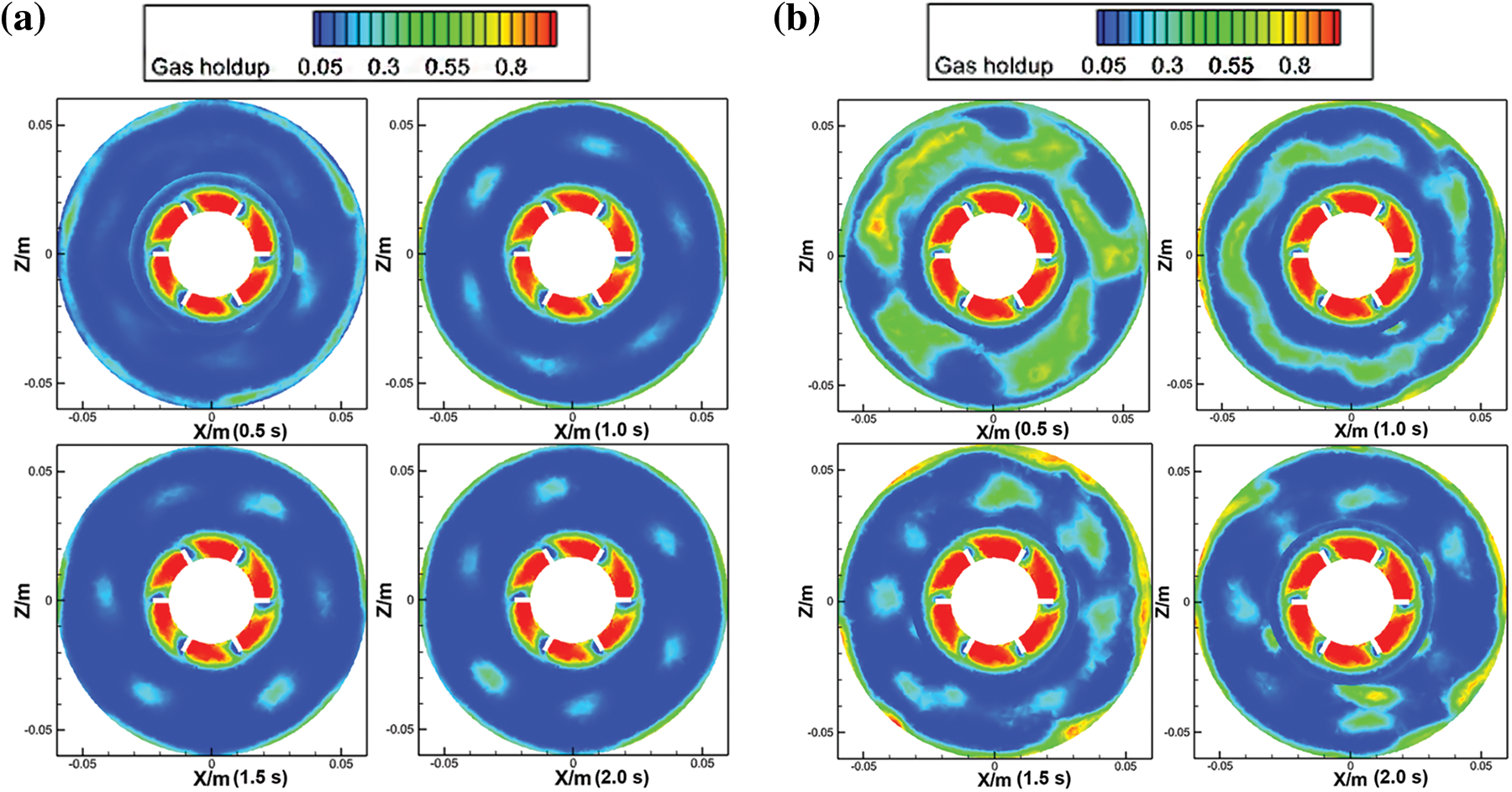
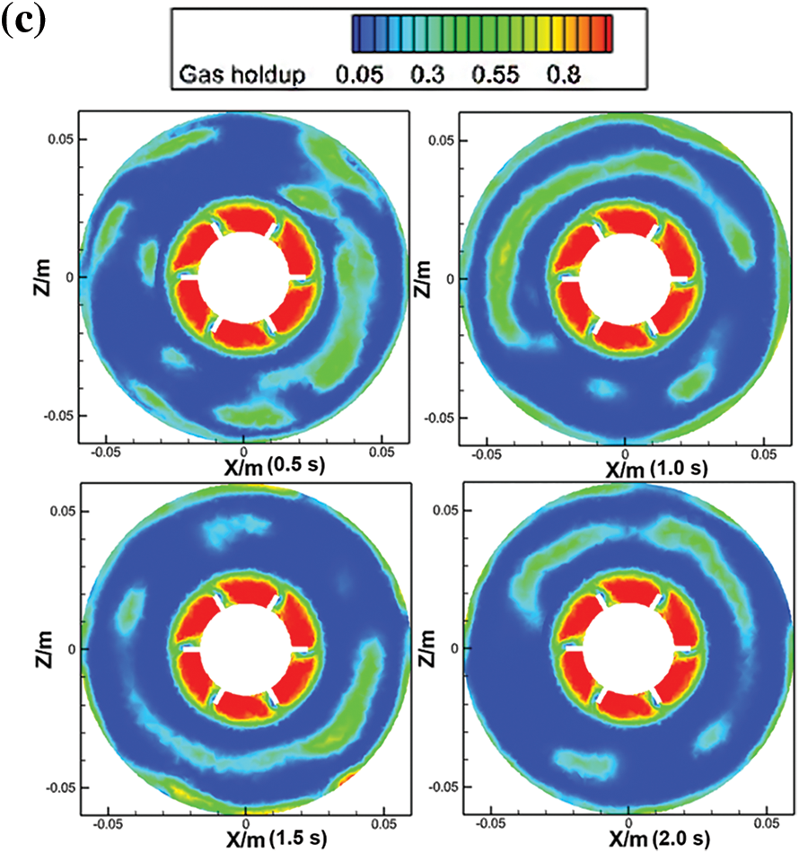
Figure 4: Gas holdup of the Rushton turbine at y = −0.055 m. (a) R1 is 1000 rpm, (b) R2 is 1250 rpm, and (c) R3 is 1500 rpm
In the foaming process, as much air as possible should be mixed into the resin by mechanical whipping, so the larger the range of disturbance is, the greater the likelihood of mixing into more air and the greater the porosity of the resulting tannin-based foam. The results were analysed at the direction of z = 0 m, as shown in Fig. 5. When the velocity is 1000 rpm, the range of disturbance is just around the blade, the tip of the blade has the greatest speed, and the top of the flow field remains almost constant, as shown in Fig. 5a. When the speed increases to 1250 rpm, the agitation range becomes wider, and the flow field has a larger velocity than ever before. At the same time, the top of the cross section presents disturbance, as exhibited in Fig. 5b. When the velocity increases from 1250 to 1500 rpm, the velocity of the flow field also increases, as shown in Fig. 5c. Furthermore, it can be concluded that the distribution of the velocity was mainly concentrated around the mixing shaft; therefore, the stirring speed and the fluid velocity were positively correlated, as shown in Figs. 6 and 7.
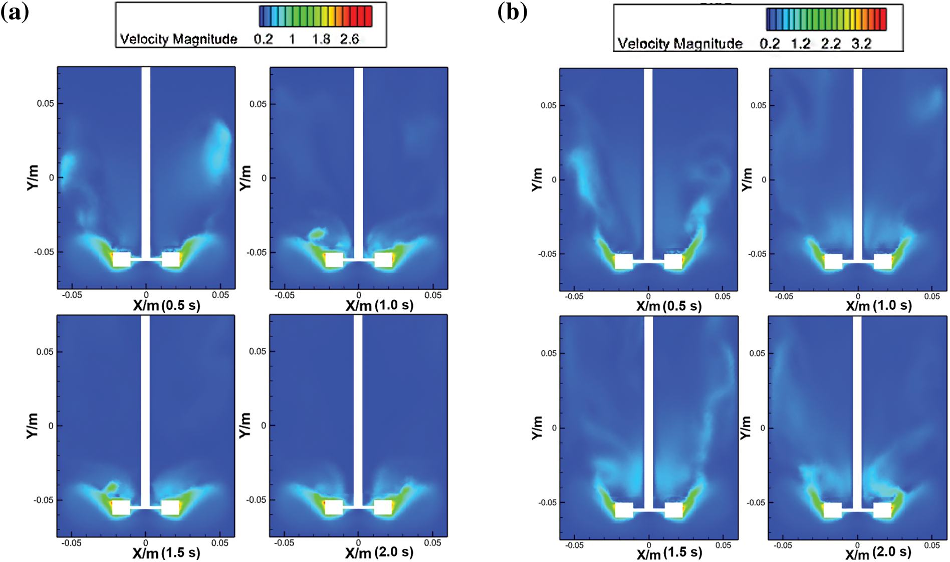
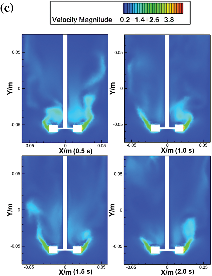
Figure 5: Velocity of the Rushton turbine at z = 0 m. (a) R1 is 1000 rpm, (b) R2 is 1250 rpm, and (c) R3 is 1500 rpm
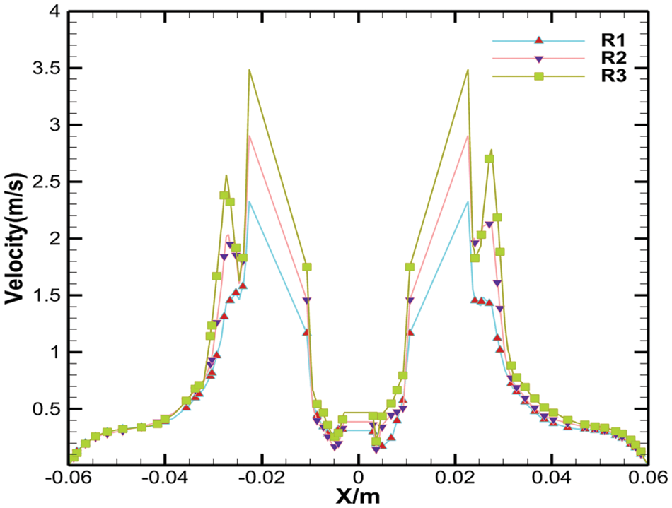
Figure 6: Velocity of the Rushton turbine in the X direction
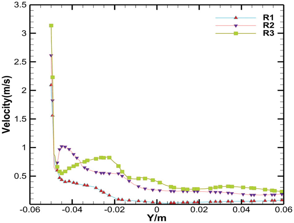
Figure 7: Velocity of the Rushton turbine in the Y direction
6.2 Effect of the Paddle Shape on the Flow Field
The eggbeater offers stirring in the flow field at three rotation speeds, which is the same as Rushton stirring. The results of eggbeater stirring are presented in Fig. 8. The gas holdup increases with increasing velocity, and the range of disturbance is wider.
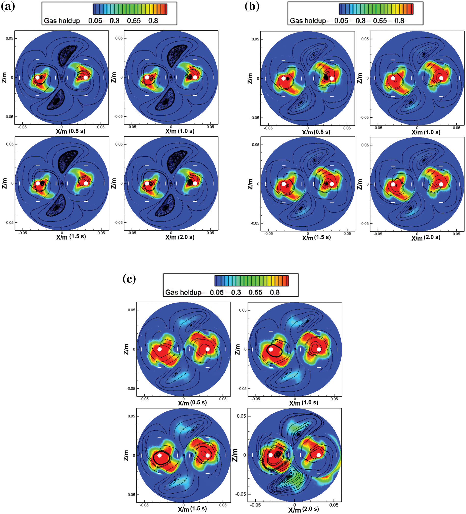
Figure 8: Gas holdup of the egg beater at y = −0.055 m. (a) D1 is at 1000 rpm, (b) D2 is at 1250 rpm, (c) D3 is at 1500 rpm
Most of the gas is present at the bottom of the eggbeater; as the rotation speed increases, the gas gradually moves closer to the wall of the beaker, and the two rotation centers cause opposite flow fields, which is the reason for the mirror gas content. This can control the gas in the beaker to provide two symmetrical parts that can make the foam construction more stable. However, the symmetrical circles caused the resin surface to sag, which is not conducive to air mixing, under either of the two paddle shapes. Compared with the result of the Rushton turbine, when the rotation speed was 1000 rpm, as shown in Fig. 4a, the eggbeater showed a narrow disturbance range, and there was no impact on the flow field except for the rotation domain; however, the disturbance of the Rushton turbine was wider, and the gas holdup was just around the top of the impeller outside of the rotation domain, as shown in Fig. 8a. As the stirring velocity increases to 1250 rpm, the Rushton turbine shows a wider range of disturbances in almost the whole cross section, as shown in Fig. 4b. At the same time, the gas appears outside the rotating region in the eggbeater paddle shape, and the position of the gas is on the axis of the tangent plane in the two rotating domains, which also presents a mirror gas distribution, as exhibited in Fig. 8b. When the rotation speed reached 1500 rpm, the distribution of gas content in the shape of an eggbeater paddle was wider than that at a stirring speed of 1250 rpm, but the trend of the gas distribution was the same as that before 1.5 s, rather than the result of the shape of the Rushton turbine paddle, which showed a more stable structure, as shown in Fig. 8c. The gas holdup in the shape of Rushton turbine impellers is larger than that in the eggbeater paddle shape in the whole flow field of the cross section. However, in the case of the two types of lower paddle shapes, the amount of tannin-based foaming precursor resin in the beaker was low inside and high outside due to stirring, as shown in Fig. 9a, but the paddle shape of the eggbeater alternated between high and low, as shown in Fig. 9b. This is because the tannin-based foaming precursor resin is removed by shearing, while the eggbeater has two rotation domains, which causes an alternating phenomenon.
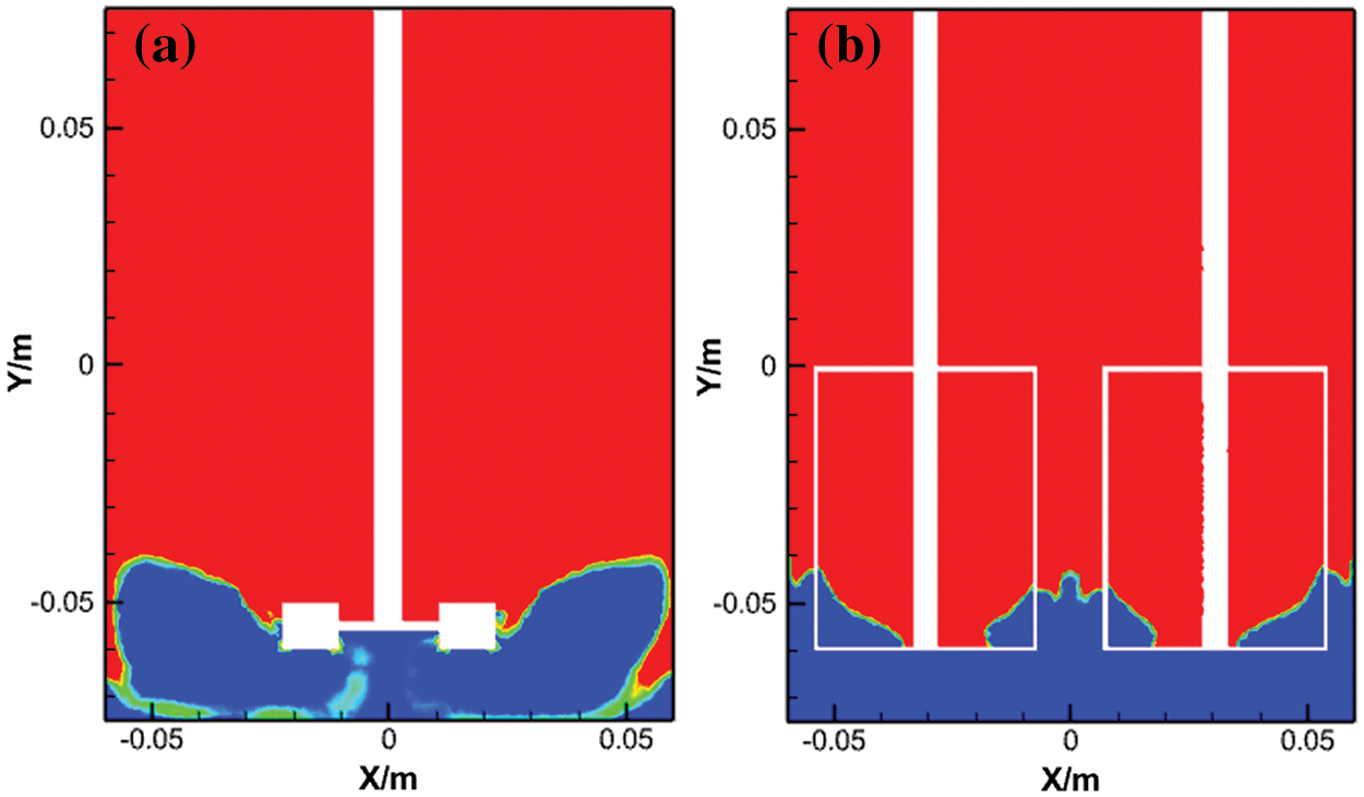
Figure 9: Gas holdup of the Rushton turbine and egg beater at z = 0 m. (a) R1 is 1000 rpm, (b) D1 is 1000 rpm
The shape of the agitation has a significant impact on the velocity of the flow field. Fig. 10 shows the velocity of the flow field for the two shapes of impellers in the xy direction. When the rotation speed was 1000 rpm, as shown in Fig. 10a, the greatest velocity of the eggbeater is outside of the impellers, and the closer impellers exhibit a lower velocity in the flow field during the process of stirring. With the increase of stirring speed, it can be seen that the velocity of the flow field outside the impeller is significantly increased and the range is expanded as shown in Fig. 10b,c. In the flow field of the eggbeater paddle shape, the velocity magnitude is lower than that of the Rushton turbine paddle shape, and the distribution of the velocity affects the calculation results, as shown in Figs. 11 and 12. The interaction between the two regions will produce opposite forces, and some will be cancelled out, whereas some will participate in rotation. The shape of the Rushton turbine impellers moves around the axis, as shown in Fig. 4, but the cross section of the eggbeater is partitioned into four parts with the presence of a vortex in every single part, as shown in Fig. 8, which provides more gas to the resin. The function of a mechanical agitator is to mix the material evenly, which is different from the function of an eggbeater, which wraps air into a resin. Therefore, the structure of the paddle shape determines the application. During the foaming process, a large amount of air arrives and stays in the resin by stirring, so it is obvious that the use of an eggbeater is more suitable for the process.
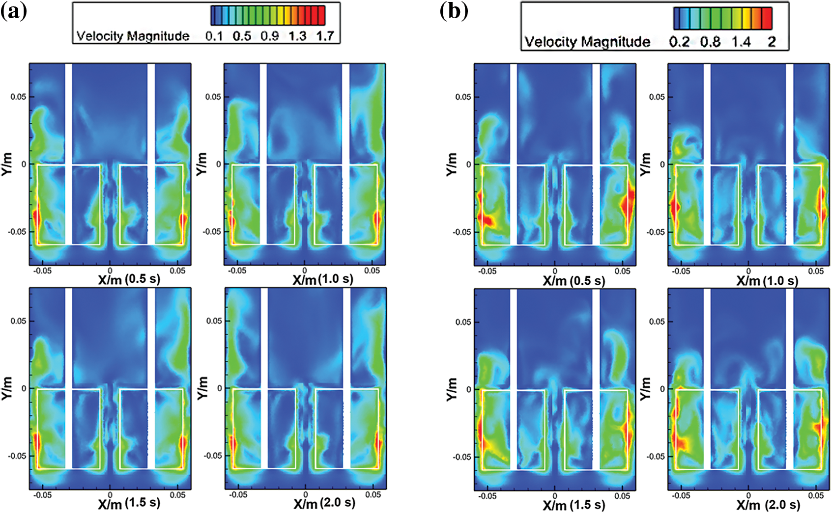
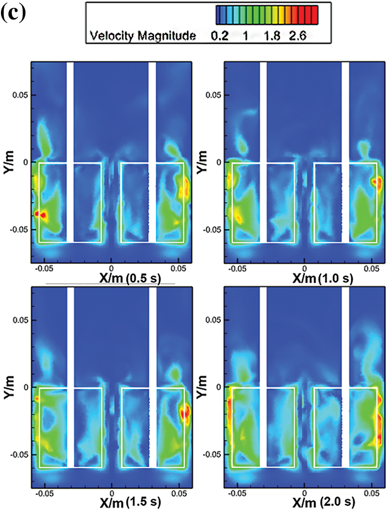
Figure 10: Velocity of the egg beater at z = 0 m. (a) D1 is at 1000 rpm, (b) D2 is at 1250 rpm, (c) D3 is at 1500 rpm
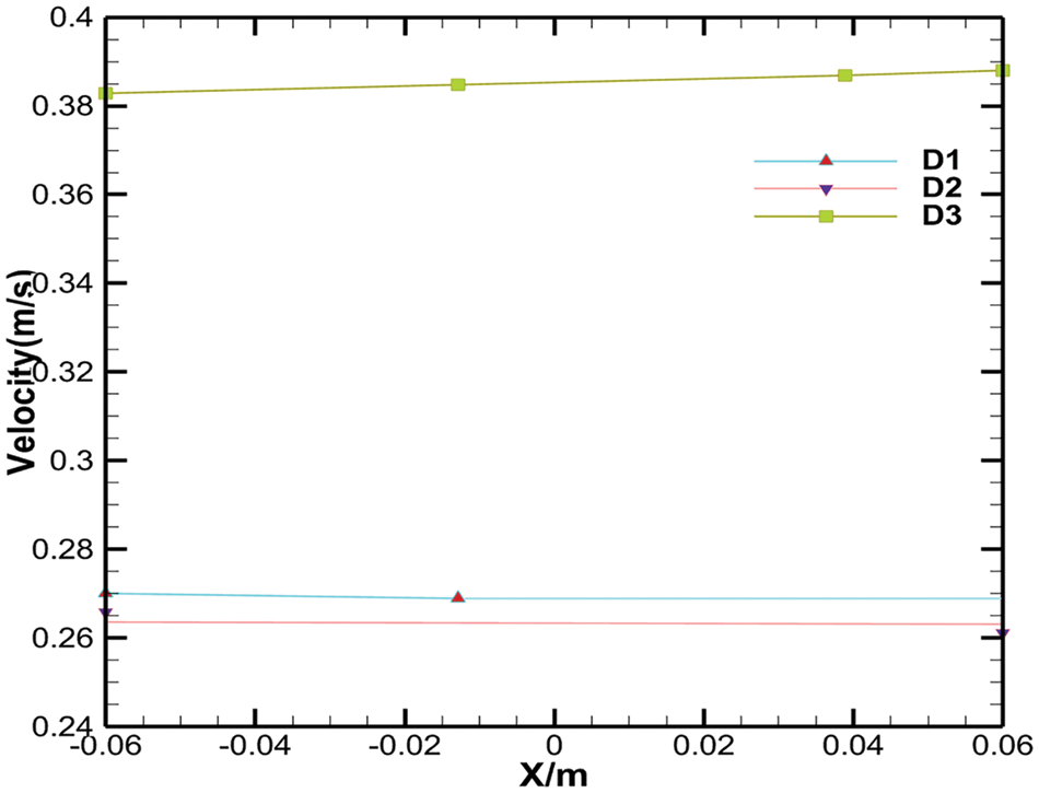
Figure 11: Velocity of the egg beater in the X direction
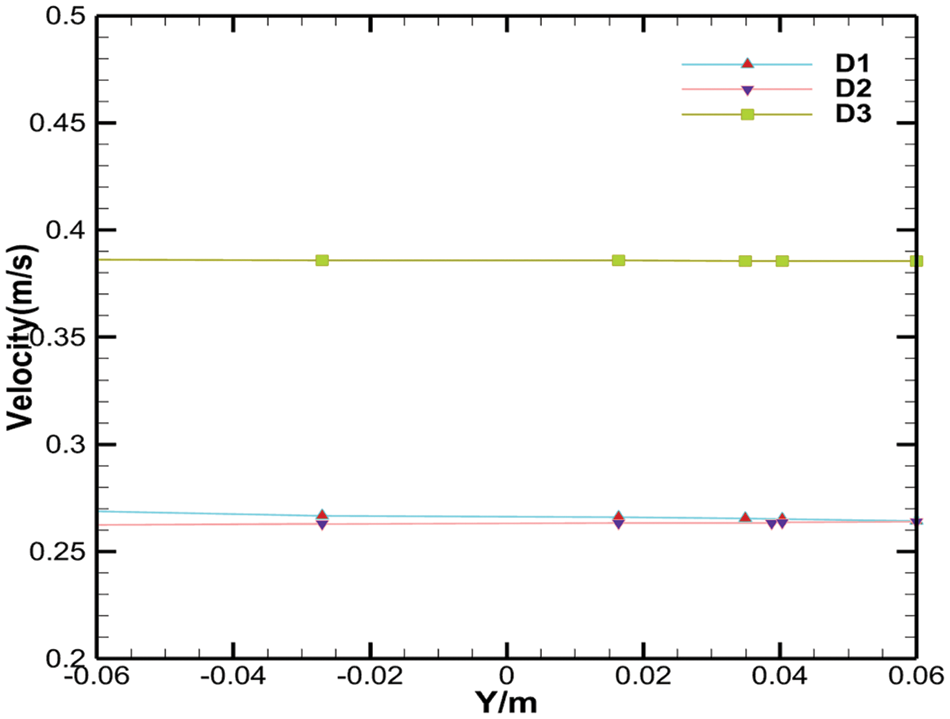
Figure 12: Velocity of the egg beater in the Y direction
The dead zones were generated by two-phase simulation, which is a significant indicator for evaluating the flow field. By comparing the dead zone in the case of two shapes of impellers and three kinds of mechanical stirring speeds, it can be concluded that the dead zone in the Rushton turbine is wider than that in the eggbeater, especially at the bottom of the simulation region, and in the radial direction. With the velocity increasing from 1000 to 1500 rpm, the dead zone in the Rushton turbine gradually decreases, but the egg beater presents the opposite phenomenon; that is, the two centers of rotation interact to cancel out some of the work leading to the dead zone. Therefore, the effect of the paddle shape and mechanical stirring speed is beneficial for the tannin-based foaming process.
In this study, two kinds of paddle shapes and three stirring speeds were simulated, and the effects on the flow field were analysed in a tannin-based foaming precursor resin. Some concluding remarks can be outlined:
(1) Under stirring at different gradient speeds, it can be concluded that by increasing the rotation speed from 1000 to 1500 rpm, the range of shear action is extended, the gas phase distribution is more uniform, and there is more entrapped air; at the same time, the mixing of the liquid phase also increases. Due to the presence of eddy currents, the velocity of the outermost layer is slightly greater than that of the inner layer, which proves that the shape of the eggbeater is less likely to cause death far from the impellers in the tannin-based foaming precursor resin process, so the use of an egg whisker is more environmentally friendly and cost effective.
(2) Concerning the effect of the impeller pattern, the eggbeater has four vortexes in the cross section, but the Rushton turbine has only one vortex, which leads to a lower disturbance of the flow field in the paddle shape of the eggbeater. The work performed in the opposite direction was partially offset, which caused the flow field of the tannin-based foaming precursor to be more stable than that of the Rushton turbine impellers. The flow pattern is also different: the Rushton turbine has upper and lower loops, but the eggbeater has multiple cycles, and those cycles can improve the mixing efficiency of tannin-based foaming precursors.
(3) When the stirring speed is set at 1500 rpm, the Rushton turbine produces a ditch, which decreases the mass transfer and leads to unevenness in the structure. At the same time, the eggbeaters showed good stirring behaviour. It is better to work with the eggbeater set at a speed of 1500 rpm to obtain a stable and even flow field of tannin-based foaming precursor resin, meaning that the state of the flow field is vital to the structure of tannin-based foam.
The results have certain reference significance for the design and optimization of tannin-based foam foaming reaction processes. In future work, the shear angle and number of impellers and the axis of the agitator should be considered.
Acknowledgement: I would like to thank all the people who have ever helped me in this paper.
Funding Statement: This work was supported by the Key Program of Applied and Basic Research in Yunnan Province (Grant No. 202101AS070008) and the National Natural Science Foundation of China (NSFC 31760187) and supported by the 111 Project (D21027), the Yunnan Provincial Academician Workstation (YSZJGZZ-2020052) and the Foreign Expert Workstation (202305AF150006). This work is also supported by the Scientific Research Foundation of Education Department of Yunnan Province (Grant Nos. 2023J0696, 2023Y0699), and Foreign Talent Introduction Program of Science and Technology Department of Yunnan Province (Grant No. 202305AO350002).
Author Contributions: The authors confirm contribution to the paper as follows: study conception and design: Xiaojian Zhou, Xinyi Chen, Lan Huang; data collection: Lan Huang, Wenbin Yuan; analysis and interpretation of results: Lan Huang, Xiaojian Zhou, Xinyi Chen, Hisham Essawy; draft manuscript preparation: Lan Huang, Xiaojian Zhou, Xinyi Chen, Hisham Essawy. All authors reviewed the results and approved the final version of the manuscript.
Availability of Data and Materials: All data generated or analyzed during this study are included in this published article.
Conflicts of Interest: The authors declare that they have no conflicts of interest to report regarding the present study.
References
1. Meikleham NE, Pizzi A. Acid- and alkali-catalyzed tannin-based rigid foams. J Appl Polym Sci. 1994;53(11):1547–56. doi:10.1002/app.1994.070531117. [Google Scholar] [CrossRef]
2. Basso MC, Pizzi A, Al-Marzouki F, Abdalla S. Horticultural/hydroponics and floral natural foams from tannins. Ind Crops Prod. 2016;87:177–81. doi:10.1016/j.indcrop.2016.04.033. [Google Scholar] [CrossRef]
3. Basso MC, Pizzi A, Polesel Maris J, Delmotte L, Colin B, Rogaume YM. MALDI-TOF, 13C NMR and FTIR analysis of the cross-linking reaction of condensed tannins by triethyl phosphate. Ind Crops Prod. 2017;95:621–31. doi:10.1016/j.indcrop.2016.11.031. [Google Scholar] [CrossRef]
4. Beninger CW, Hosfield GL. Antioxidant activity of extracts, condensed tannin fractions, and pure flavonoids from phaseolus vulgaris l. Seed coat color genotypes. J Agric Food Chem. 2003;51(27):7879–83. doi:10.1021/jf0304324. [Google Scholar] [PubMed] [CrossRef]
5. Benyahya S, Aouf C, Caillol S, Boutevin B, Pascault JP, Fulcrand H. Functionalized green tea tannins as phenolic prepolymers for bio-based epoxy resins. Ind Crops Prod. 2014;53:296–307. doi:10.1016/j.indcrop.2013.12.045. [Google Scholar] [CrossRef]
6. Lacoste C, Basso MC, Pizzi A, Laborie MP, Celzard A, Fierro V. Pine tannin-based rigid foams: mechanical and thermal properties. Ind Crops Prod. 2013;43:245–50. doi:10.1016/j.indcrop.2012.07.039. [Google Scholar] [CrossRef]
7. Zhou X, Li B, Xu Y, Essawy H, Wu Z, Du G. Tannin-furanic resin foam reinforced with cellulose nanofibers (CNF). Ind Crops Prod. 2019;134:107–12. doi:10.1016/j.indcrop.2019.03.052. [Google Scholar] [CrossRef]
8. Yuan W, Xi X, Zhang J, Pizzi A, Essawy H, Du G, et al. A novel strategy inspired by steaming Chinese steamed bread for preparation of tannin-furanic rigid bio-foam. Constr Build Mater. 2023;376:131035. doi:10.1016/j.conbuildmat.2023.131035. [Google Scholar] [CrossRef]
9. Szczurek A, Fierro V, Pizzi A, Stauber M, Celzard A. A new method for preparing tannin-based foams. Ind Crops Prod. 2014;54:40–53. doi:10.1016/j.indcrop.2014.01.012. [Google Scholar] [CrossRef]
10. Basheer AA, Bharathesh K. Effect of baffle configuration on hydrodynamics and solid suspension in a continuous stirred vessel. Chem Eng Commun. 2022;209(10):1413–22. doi:10.1080/00986445.2021.1975681. [Google Scholar] [CrossRef]
11. Ali BA, Falleiro LH. Effect of baffle configuration on performance of batch stirred vessel. Korean J Chem Eng. 2022;39(5):1146–57. doi:10.1007/s11814-021-1008-9. [Google Scholar] [CrossRef]
12. Yang T, Takahashi K. Effect of impeller blade angle on power consumption and flow pattern in horizontal stirred vessel. J Chem Eng Jpn. 2010;43:635–40. doi:10.1252/jcej.10we046. [Google Scholar] [CrossRef]
13. Khopkar AR, Rammohan AR, Ranade VV, Dudukovic MP. Gas-liquid flow generated by a rushton turbine in stirred vessel: carpt/ct measurements and cfd simulations. Chem Eng Sci. 2005;60(8):2215–29. [Google Scholar]
14. Barros PL, Ein-Mozaffari F, Lohi A. Effect of agitation and aeration on gas dispersion efficiency in coaxial mixers containing yield-pseudoplastic fluids: experimental and numerical analysis. Can J Chem Eng. 2024;102(2):911–24. doi:10.1002/cjce.v102.2. [Google Scholar] [CrossRef]
15. Jin J, Bu S, Fan Y, Han J, Yin K, Chen W. Flow stirred by open turbine: a modal analysis of multiscale flow characteristics. Asia-Pac J Chem Eng. 2024;19(3):e3055. doi:10.1002/apj.v19.3. [Google Scholar] [CrossRef]
16. Li X, Guan X, Zhou R, Yang N, Liu M. CFD simulation of gas dispersion in a stirred tank of dual rushton turbines. 2017;15(4):20160221. [Google Scholar]
17. Zhang H, Wang Y, Sayyar A, Wang T. Experimental study on breakup of a single bubble in a stirred tank: effect of gas density and liquid properties. AIChE J. 2023;69(1):e17511. doi:10.1002/aic.v69.1. [Google Scholar] [CrossRef]
18. Meng T, Wang Y, Wang S, Qin S, Zhang Q, Wang Y, et al. Exploration of multishafts stirred reactors: an investigation on experiments and large eddy simulations for turbulent chaos and mixing characteristics. Ind Eng Chem Res. 2024;63(5):2441–56. doi:10.1021/acs.iecr.3c04042. [Google Scholar] [CrossRef]
19. Pang Z, Yang J, Cai Y. Effects of rotational speed on the microstructure and mechanical properties of 2198-T8 Al-Li alloy processed by friction spot welding. Materials. 2023;16(5):1807. [Google Scholar] [PubMed]
20. Luan DY, Zhou SJ, Duan H. Research on mechanism of fluid flow characteristics in a stirred tank with stirrer composed of perturbed six-bent-bladed turbine. Appl Mech Mater. 2014;543–547:85–9. [Google Scholar]
21. Guntzburger Y, Fradette L, Farhat M, Héniche M, Tanguy PA, Takenaka K. Effect of the geometry on the performance of the maxblendTM impeller with viscous newtonian fluids. Asia-Pac J Chem Eng. 2009;4(5):528–36. doi:10.1002/apj.v4:5. [Google Scholar] [CrossRef]
22. Roman RV, Tudose RZ. Studies on transfer processes in mixing vessels: hydrodynamic of the modified rushton turbine agitators in gas—Liquid dispersions. Chem Eng J Biochem Eng J. 1996;61(2):83–93. doi:10.1016/0923-0467(95)03033-6. [Google Scholar] [CrossRef]
23. Khapre A, Munshi B. Data on the mixing of non-newtonian fluids by a rushton turbine in a cylindrical tank. Data Brief. 2016;8:1416–20. doi:10.1016/j.dib.2016.08.023. [Google Scholar] [PubMed] [CrossRef]
24. Luan D, Zhang S, Lu J, Zhang X. Chaotic characteristics enhanced by impeller of perturbed six-bent-bladed turbine in stirred tank. Results Phys. 2017;7:1524–30. doi:10.1016/j.rinp.2017.04.030. [Google Scholar] [CrossRef]
25. Kasat GR, Khopkar AR, Ranade VV, Pandit AB. CFD simulation of liquid-phase mixing in solid-liquid stirred reactor. Chem Eng Sci. 2008;63(15):3877–85. doi:10.1016/j.ces.2008.04.018. [Google Scholar] [CrossRef]
26. Nagata S. Power characteristics of mixing impellers. J Soc Mech Eng. 1956;59:235–41. [Google Scholar]
27. Khaledi HA, Smith IE, Unander TE, Nossen J. Investigation of two-phase flow pattern, liquid holdup and pressure drop in viscous oil-gas flow. Int J Multiphase Flow. 2014;67:37–51. doi:10.1016/j.ijmultiphaseflow.2014.07.006. [Google Scholar] [CrossRef]
28. Lee BW, Dudukovic MP. Determination of flow regime and gas holdup in gas-liquid stirred tanks. Chem Eng Sci. 2014;109:264–75. doi:10.1016/j.ces.2014.01.032. [Google Scholar] [CrossRef]
29. Heidari A. CFD simulation of impeller shape effect on quality of mixing in two-phase gas–liquid agitated vessel. Chin J Chem Eng. 2020;28(11):2733–45. doi:10.1016/j.cjche.2020.06.036. [Google Scholar] [CrossRef]
30. Mansour M, Kopparthy S, Thévenin D. Investigations on the effect of rotational speed on the transport of air-water two-phase flows by centrifugal pumps. Int J Heat Fluid Flow. 2022;94:108939. doi:10.1016/j.ijheatfluidflow.2022.108939. [Google Scholar] [CrossRef]
Cite This Article
 Copyright © 2024 The Author(s). Published by Tech Science Press.
This work is licensed under a Creative Commons Attribution 4.0 International License , which permits unrestricted use, distribution, and reproduction in any medium, provided the original work is properly cited.
 Downloads
 Citation Tools