
 Submit a Paper
 Propose a Special lssue
 Open Access
ARTICLE

Influence of the Ambient Temperature on the Efficiency of Gas Turbines
Laboratory of Aeronautics and Propulsive Systems University of Sciences and Technology Mohamed Boudiaf Mechanical Engineering Faculty, Oran, 3100, Algeria
* Corresponding Author: Mahdi Goucem. Email:
(This article belongs to the Special Issue: Materials and Energy an Updated Image for 2023)
Fluid Dynamics & Materials Processing 2024, 20(10), 2265-2279. https://doi.org/10.32604/fdmp.2024.052365
Received 30 March 2024; Accepted 11 June 2024; Issue published 23 September 2024
 View Full Text
 Download PDF
Abstract
In hot and arid regions like the Saharan area, effective methods for cooling and humidifying intake air are essential. This study explores the utilization of a water trickle cooler as a promising solution to meet this objective. In particular, the HASSI MESSAOUD area is considered as a testbed. The water trickle cooler is chosen for its adaptability to arid conditions. Modeling results demonstrate its effectiveness in conditioning air before it enters the compressor. The cooling system achieves a significant temperature reduction of 6 to 8 degrees Celsius, enhancing mass flow rate dynamics by 3 percent compared to standard cases without cooling. Moreover, the cooling system contributes to a remarkable 10 percent reduction in power consumption of gas turbines and a notable 10 percent increase in turbine efficiency. These findings highlight the potential of water trickle coolers in improving the performance and efficiency of gas turbine systems in hot and dry climates.Keywords
Nomenclature
| T0 | Ambient air temperature (K) |
| T | Temperature (K) |
| p0 | Ambient air pressure (Bars) |
| P | Power (kw) |
| m | The mass flow rate (kg/s) |
| mC | Fuel flow rate (kg/s) |
| mT | Total air flow rate (kg/s) |
| A | Area (m2) |
| U(i, j, k) | Instantaneous speed in three directions (m/s) |
| NTH | Rotational speed of the high-pressure turbine (Rpm) |
| NTB | Rotational speed of the low-pressure turbine (Rpm) |
| ρ | Density (kg/m3) |
| | Enthalpy change (kJ/kg) |
| ηis | Efficiency isentropic (−) |
| ηC | Combustion chamber efficiency (−) |
| Wac | Actual work (kJ/kg) |
| Wis | Isentropic work (kJ/kg) |
| Cp | The specific heat at constant pressure (kJ/kg.K) |
| Fi | Transfer function |
| t | Time (s) |
| K | Turbulent kinetic energy (m2/s2) |
| ω | Dissipation rate of turbulent kinetic energy (1/s) |
| β, β*, a1 | Interior region constants (−) |
| σk, σω | Interior region constants (−) |
| SST | Turbulance Model |
| µ | Viscosity (kg/m.s) |
| µt | Viscosity at the wall (kg/m.s) |
| y | Distance from the wall (m) |
Efficiency optimization in gas turbines, crucial for energy production and sustainability, involves strategies like pre-cooling to optimize inlet air temperature, enhancing power output and thermal efficiency. Computational Fluid Dynamics (CFD) serves as a vital tool for analyzing fluid dynamics and heat transfer, offering insights into operational conditions and facilitating the implementation of turbine air inlet cooling to improve existing gas turbine efficiency. Farzaneh-Gord et al. [1] compare traditional methods with a novel turboexpander approach for gas turbine inlet air cooling at the Khangiran refinery, recommending turboexpanders as the most economically feasible option. Nematollahi et al. [2] propose integrated cooling systems Active Magnetic Regenerative (AMD) and Active Electrocaloric (AED), utilizing exhaust heat from gas turbines to operate absorption coolers and regenerate desiccant wheels, showcasing the effectiveness of fogging in gas turbine intake air cooling while reducing cooling capacity requirements. Naeim et al. [3] conduct a numerical study comparing three fogging strategies: direct fogging, fogging with a natural gas heat exchanger (FNGE), and FNGE with a storage tank (FNGET), using a discrete phase model (DPM) with standard k-ω turbulence model. Their computational parametric study on a gas turbine compressor inlet duct optimized FNGET cooling by analyzing duct length, nozzle number, droplet diameter uniformity, and nozzle angle’s impact on compressor inlet air temperature and relative humidity (RH). Cha et al. [4] devise a novel setup for GT-CO2 CCPP integrating turbine inlet air cooling (TIAC) and heat-recovering HR systems, leveraging Liquefied natural gas cold energy. The condensed CO2 in TIAC enhances power output by cooling gas turbine inlet air and recovering energy from the CO2 bottoming cycle, thereby boosting efficiency. Moradì et al. [5] demonstrate the efficacy of gas-turbine inlet air cooling in increasing power output at high temperatures by lowering inlet air temperature using chilled water, resulting in a substantial power increase and highlighting the potential of pre-cooling systems for enhancing gas turbine efficiency. Kakaras et al. [6] emphasize the negative impact of rising ambient temperatures on gas turbine power output, conducting a comprehensive evaluation of various intake air cooling methods to counter this effect, considering their performance and economic viability across different climatic conditions. Arabi et al. [7] explore the impact of elevated inlet air temperature on gas power plant efficiency, showcasing wet compression as the most effective in enhancing cycle efficiency and reducing fuel consumption based on MATLAB simulations conducted at the Zanbagh power plant. Santos et al. [8] investigate gas turbine inlet air cooling’s feasibility in high-demand regions, finding the absorption chiller most effective for increasing annual energy generation with lower unit energy costs, while the evaporative cooler showed limited cooling potential but lower costs. Bin-Shams et al. [9] investigate reduced propane recovery at a gas processing plant during summer, proposing an inlet air cooling system utilizing a cold residue-gas stream to enhance the plant’s refrigeration system. The study revealed that cooling the gas turbine’s inlet air from 40°C to 15°C significantly increased propane production by 245 bbl/day, resulting in daily savings of $18,000, with a calculated payback period of 8.5 months and high internal rate of return (IRR) and Net Present Value (NPV), indicating a lucrative investment opportunity. Deymi-Dashtebayaz et al. [10] investigate various compressor inlet air cooling techniques to enhance gas turbine performance at a refinery, identifying the absorption chiller as the most effective method for reducing inlet air temperature and improving thermal and exergy efficiencies. They found that employing the pressure drop station method offered the most economically viable option, while Pourhedayat et al. [11] addresse challenges posed by elevated intake air temperatures on gas turbine power plants, proposing a comprehensive review of pre-cooling strategies to mitigate performance decline and emissions, considering diverse technologies and regional climate conditions for future research directions. The influence of ambient conditions on gas turbine cycle performance was studied by Matjanov [12]. Results from a 28.1 MW gas turbine in Tashkent Combined Heat and Power (CHP) reveal decreased power output and efficiency at +45°C ambient temperature. An absorption chiller utilizing waste gases from the Heat recovery steam generator (HRSG) emerges as the most economically viable solution for cooling, maintaining nominal values for CHP performance. While solar energy integration is feasible, it proves economically beneficial only when HRSG waste gases lack sufficient heat. Marzouk et al. [13] highlight the significance of gas turbine power plants in global energy generation due to their cost-effectiveness and quick installation, yet their performance is hindered by ambient temperature fluctuations, resulting in efficiency decline. Their study evaluates chiller and evaporative cooling methods for a 264 MW gas turbine plant in Korymat, southern Egypt, revealing that chiller cooling yields an annual power gain of 117,027 MWh with a net cash flow of $3,787,537, while evaporative cooling achieves 86,118 MWh with a net cash flow of $4,503,548. AL-Hamdan et al. [14] emphasize the critical role of air mass flow rate and inlet air temperature on gas turbine performance, noting the adverse effect of higher temperatures on power output and heat rate. Their study focuses on evaporative cooling as a method to lower inlet air temperature, revealing an 11.07% increase in power output and a 4% decrease in heat rate when inlet air temperature decreases from 50°C to 26°C, offering insights valuable to power producers. Cabarcas et al. [15] investigate strategies to bolster gas turbine power plant efficiency in tropical climates, where high temperatures and humidity can diminish output. Their study assesses the integration of evaporative cooling, desiccant dehumidification, and Maisotsenko cooler for inlet air cooling, showcasing a potential power output improvement of over 2 MW at peak temperatures. Moreover, they demonstrate the viability of utilizing turbine exhaust gases for regeneration air heating, reducing compressor inlet temperature by an average of 11.5°C, offering a promising approach to counteract performance declines in hot tropical conditions. Meanwhile, Yu et al. [16] delve into enhancing fuel and gas turbine energy efficiency through cyclic air intercooling, focusing on the cooling contact method employing a thermopressor. Their experimental findings highlight the significance of optimizing water injection in the thermopressor, with a relative amount ranging from 4% to 10%, resulting in a notable increase in airflow pressure without significant pressure loss, thus promoting efficient incomplete liquid evaporation. Bunker [17] underscores the pivotal role of advanced heat transfer and cooling techniques in advancing high-efficiency gas turbine engines. While traditional thermal management methods include internal convective cooling and external surface film cooling, Bunker’s paper explores innovative approaches such as forced convective cooling with unconventional turbulators and swirl-cooling chambers to enhance aero-thermal-mechanical turbine engine performance. Meanwhile, Dinindu [18] evaluates the performance of the Kelanitissa gas turbine unit under varying ambient air temperatures, utilizing operational data and thermodynamic principles for analysis. Findings indicate a notable efficiency decrease from the designed 25.8% to 21.2% at 33°C ambient temperature, necessitating proposed inlet air cooling with a cooling load estimated at 679.87 RT. Cost analysis suggests an 11-year payback period for the project, with potential annual savings of Rs. 6 Mn achieved by reducing the inlet air temperature to the ISO value of 15°C. Gopinath et al. [19] underscore the crucial influence of inlet air temperature on gas turbine performance, where power output correlates directly with air mass flow rate. To mitigate the impact of rising atmospheric temperatures, they explore the effectiveness of techniques such as evaporative coolers, vapor compression chillers, and absorption chillers in lowering inlet air temperature. Their study compares the performance of a 100 MW gas turbine model with varying inlet air temperatures using data from GT PRO software, commonly employed for power plant design. Meanwhile, Didi-Asmara et al. [20] highlight the adverse effects of ambient temperatures on gas turbine power output and efficiency attributable to decreased air density. They propose absorption chiller cooling as a supplementary measure, utilizing turbine exhaust heat to produce chilled water for cooling intake air via a heat exchanger. Investigations, leveraging operation data from Universiti Teknologi Petronas, indicate the potential of this system to enhance gas turbine performance during periods of heightened ambient temperatures. Ghanaatpisheh et al. [21] stress the importance of optimizing turbine compressor inlet air cooling methods and power recovery. They explore various cooling techniques for gas turbines in Fars power plants, selecting a media evaporative air cooler system based on technical and economic evaluations. Performance tests reveal significant power increases, with gas units showing an 11 MW equivalent rise (14.5%) and steam combined cycle units experiencing a 1.2 MW (6.2%) increase during summer conditions. Alok et al. [22] conduct a parametric study on the impact of factors on plant performance parameters, finding that vapor absorption inlet air cooling enhances gas turbine efficiency by up to 7.48% and specific work by over 18%. However, adoption in combined cycles results in decreased plant efficiency despite a more than 7% increase in output. They identify the optimum compressor inlet temperature for maximum specific work output to be 25°C, below which further reduction adversely affects plant efficiency. Sakhaei et al. [23] investigate the effect of lowering compressor inlet air temperature on power and efficiency, focusing on fog pumping as an alternative to traditional evaporative coolers in gas turbine cooling cycles. Their study evaluates various cooling methods to enhance power production and cost efficiency, stressing the importance of selecting the most suitable method based on site conditions and operational needs. Additionally, they conduct a relative comparison among different cooling techniques. Suneetha et al. [24] concentrate on enhancing specific power output by reducing inlet air temperature. They estimate gas turbine power output incrementally until standard temperature and pressure conditions are reached using chiller coils for inlet air cooling. The study investigates the relationship between power output and temperature variation, with the aim of optimizing specific power output through inlet air temperature reduction. Block-Novelo et al. [25] examine the conflict between greening heat engines and maintaining energy efficiency, where emissions reduction measures incur added external energy costs. The complexities surrounding nitrogen oxides (NOx) formation necessitate limiting maximum fuel combustion temperature, albeit at the expense of diminishing engine fuel-energy efficiency.
This study focuses on modeling a gas turbine both with and without pre-cooling using CFD. In this numerical study, we begin with an introduction, followed by the numerical and geometric modeling of the trickle cooler using the k-ω SST turbulence model. The 3D simulation is conducted within the computed domain. This analysis utilizes the Gambit mesh and the FLUENT solver to investigate the effect of the trickle cooler on gas turbine parameters such as outlet temperature, airflow, power, and efficiency. Finally, conclusions are drawn, and suggestions for further work are provided.
2 Description of the Water Trickle Cooling System
In this study, we have chosen the water evaporation cooler because it is favorable for hot and dry areas (climate of the Saharan region). Humidification is used to increase the water content in the air, the absolute humidity will increase, and the air temperature will decrease. For humidification to occur, there must be close and intensive contact between the air and the moisture source.
The trickle humidifier with pump recirculation (Fig. 1). works as follows:
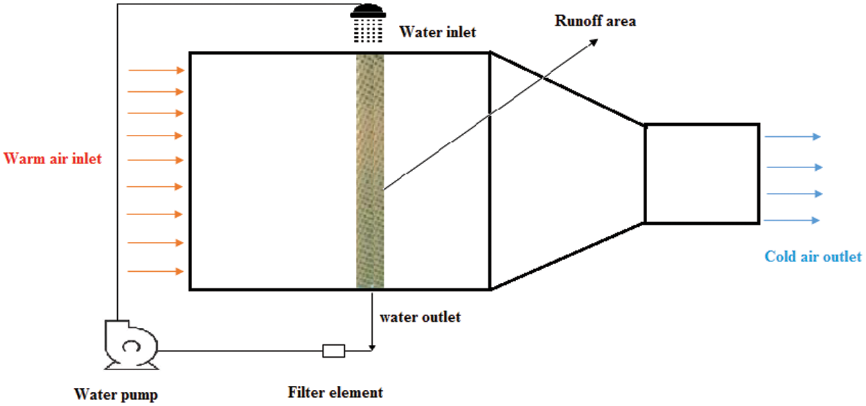
Figure 1: Trickle cooler with water recycling
- The water flows over a large surface area.
- The air flows through the thickness of this support and is in contact with the humid surface.
- The water evaporates due to the heat given off by the air.
The compressor inlet dimensions play a crucial role in determining the performance and efficiency of the system. These dimensions encompass the size and shape of the compressor inlet. Typically, the dimensions are carefully designed to ensure optimal airflow into the compressor while minimizing losses due to turbulence or restrictions. Factors such as the cross-sectional area and inlet shape are meticulously considered to achieve uniform airflow distribution and to prevent aerodynamic inefficiencies. Moreover, the inlet dimensions must accommodate the desired mass flow rate of air into the compressor, ensuring adequate supply for the intended application without causing excessive pressure losses or flow separation. Properly sized compressor inlets are essential for maintaining efficient operation, preventing stall or surge conditions, and optimizing overall system performance (Fig. 2).
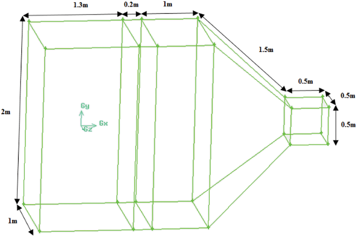
Figure 2: Compressor inlet dimensions
The figure depicts the inlet prior to entering the compressor. The mesh comprises hybrid hexahedral and tetrahedral elements [26], amounting to approximately 1,200,000 cells.
The 3D simulation takes place within the computed domain (Fig. 3a), characterized by dry inlet airflow as the inlet boundary condition highlighted in yellow, wet outlet airflow at the outlet in blue, and also a boundary condition represented by the mass flow rate of inlet water vapor in red. The outlet at the bottom serves as a mass flow outlet water boundary condition. The exterior faces function as symmetry boundary conditions without color, as shown in Fig. 3b.
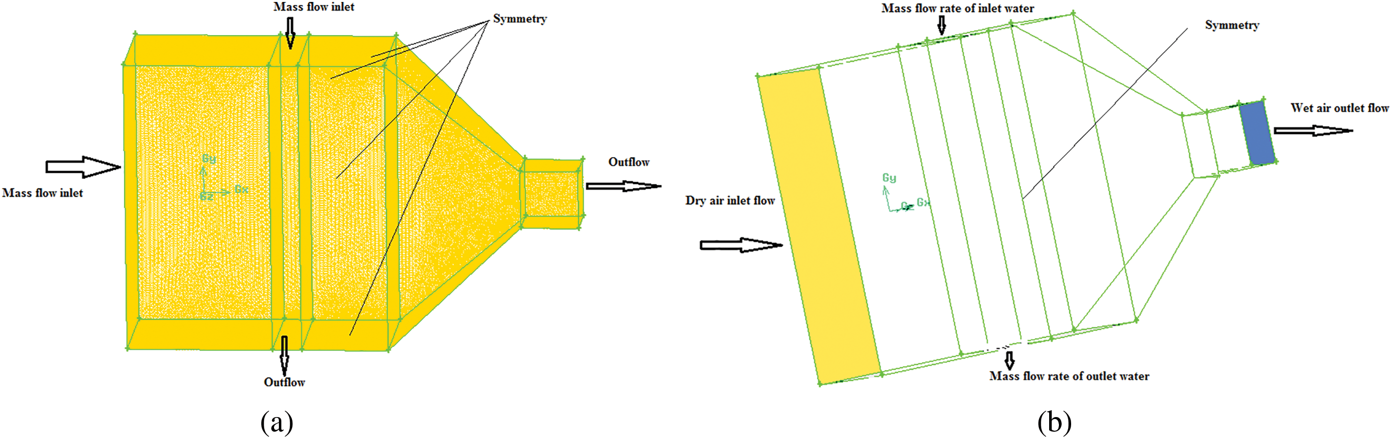
Figure 3: Grid domain and boundary conditions
After creating three simulation cases with mesh sizes of 0.8, 1.2, and 2 million cells respectively to investigate mesh independence, the results reveal that with 0.8 million cells, convergence is achieved, surpassing the user-defined tolerance threshold. However, upon increasing the grid resolution to 1.2 million cells, convergence is achieved with residuals of 104 and imbalances of less than 1%, the simulated value falls within the acceptable range.
Upon further grid refinement to 2 million cells, the simulated value also falls within the acceptable range. This suggests that a solution value independent of grid resolution has been reached Fig. 4. For subsequent analysis, the case with 1.2 million cells can be utilized as it provides results within the user-specified tolerance.
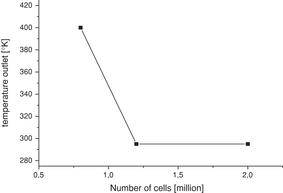
Figure 4: Mesh independence study
The calculation domain is considered 3D, unsteady, incompressible and turbulent, for the turbulence model K-ω SST. The governing equations are the Unsteady Reynolds-Averaged Navier-Stokes (URANS) equations, which have been solved by the numerical finite volumes method with standard pressure-based solver, and PISO approach to treat the pressure-velocity coupling. Both momentum and modified turbulent viscosity have been treated by using second order upwind approach.
The turbine model inlet employed in this study is created using a grid generated by the Gambit grid generator. The Fluent ANSYS 17.1 CFD analyzer is then employed to conduct a detailed analysis, focusing on key performance metrics such as power output and efficiency. The utilization of the Gambit grid generator ensures a robust and accurate representation of the turbine geometry, while the Fluent ANSYS 17.1 CFD analyzer allows for a comprehensive examination of fluid dynamics and heat transfer within the turbine inlet. By leveraging these advanced computational tools, our study aims to provide an in-depth understanding of the turbine’s behavior under different operating conditions, particularly comparing scenarios with and without pre-cooling. This approach facilitates a detailed investigation into the impact of pre-cooling on the power and efficiency of the turbine, contributing valuable insights to the field of gas turbine technology and guiding efforts towards enhanced performance and energy efficiency.
In order to account for unsteadiness in the calculations, the continuity equation for unsteady 3D compressible flow is expressed as follows:
The Navier-Stokes equations are a set of nonlinear partial differential equations of the second order. Solving these equations involves forming three equations for the three unknowns (velocity components) in a fluid flow. Additionally, the introduction of appropriate boundary conditions is crucial to facilitate the solution of these equations.
The SST (Shear-Stress Transport) k-ω turbulence model stands out as a versatile and widely applied approach in aerodynamic simulations. This two-equation model for eddy viscosity serves as a hybrid, seamlessly integrating aspects from both the k-ω and k-epsilon turbulence models. The inherent strengths of each model are strategically combined, enhancing the overall performance and applicability of the SST k-ω model.
The k-ω model is particularly adept at simulating flow in the viscous sublayer, where the fluid near a solid boundary is strongly influenced by viscosity effects. In this region, the k-ω model excels in capturing the intricate dynamics of the boundary layer, providing accurate predictions of turbulence behavior in close proximity to walls.
Turbulence kinetic energy equation
Specific dissipation rate
Turbulent viscosity
The function F1 and F2 is defined by:
1. Create the mesh geometry and the large mesh domain for different configurations.
2. Discretize the mesh domain using Gambit.
3. Define boundary conditions.
4. Set resolution methods in FLUENT.
5. Fluent delivers outlet air temperature (T), and mass flow rate (m).
The parameters acquired from FLUENT are inputted into the Fortran programming language to compute the characteristics of the gas turbine, specifically power and efficiency.
Governing equations for turbine modeling:
Power Output (P):
The power output of a gas turbine can be related to the efficiency isentropic (ηis), the mass flow rate (m), and the enthalpy change (
The efficiency isentropic (ηis): The isentropic efficiency is related to the actual work done (
where:
The enthalpy equation for an ideal gas can be expressed as:
Based on the comprehensive analysis of meteorological data gathered during our training course conducted in the HMD area, notable patterns emerged in the environmental conditions of the region. Particularly, we observed that humidifying the intake air is most suitable during daytime periods. This finding stems from the characteristic temperature fluctuations in the Hassi Messaoud region, where ambient temperatures drop during the night, coinciding with an increase in relative humidity.
In light of these observations, we selected a trickling water cooler for this study. This cooling system was deemed optimal for simultaneously cooling and humidifying the incoming air, given its adaptability to the prevalent hot and dry conditions of the Hassi Messaoud desert region. The choice of this cooling method is crucial for its efficacy in addressing the specific climatic challenges of the area.
Throughout our investigation, based on the characteristics of the turbine presented in Table 1, we focused on key parameters such as ambient air temperature (T0), mass flow rate (m), output power (P), and efficiency (ηis) of the gas turbine plant. These parameters serve as essential metrics for evaluating the performance of the gas turbine under the influence of the selected trickling water cooler. Our study aims to elucidate the intricate relationship between the cooling and humidification system and the gas turbine’s efficiency, output power, and overall operational characteristics in the challenging climatic conditions of the Hassi Messaoud region.
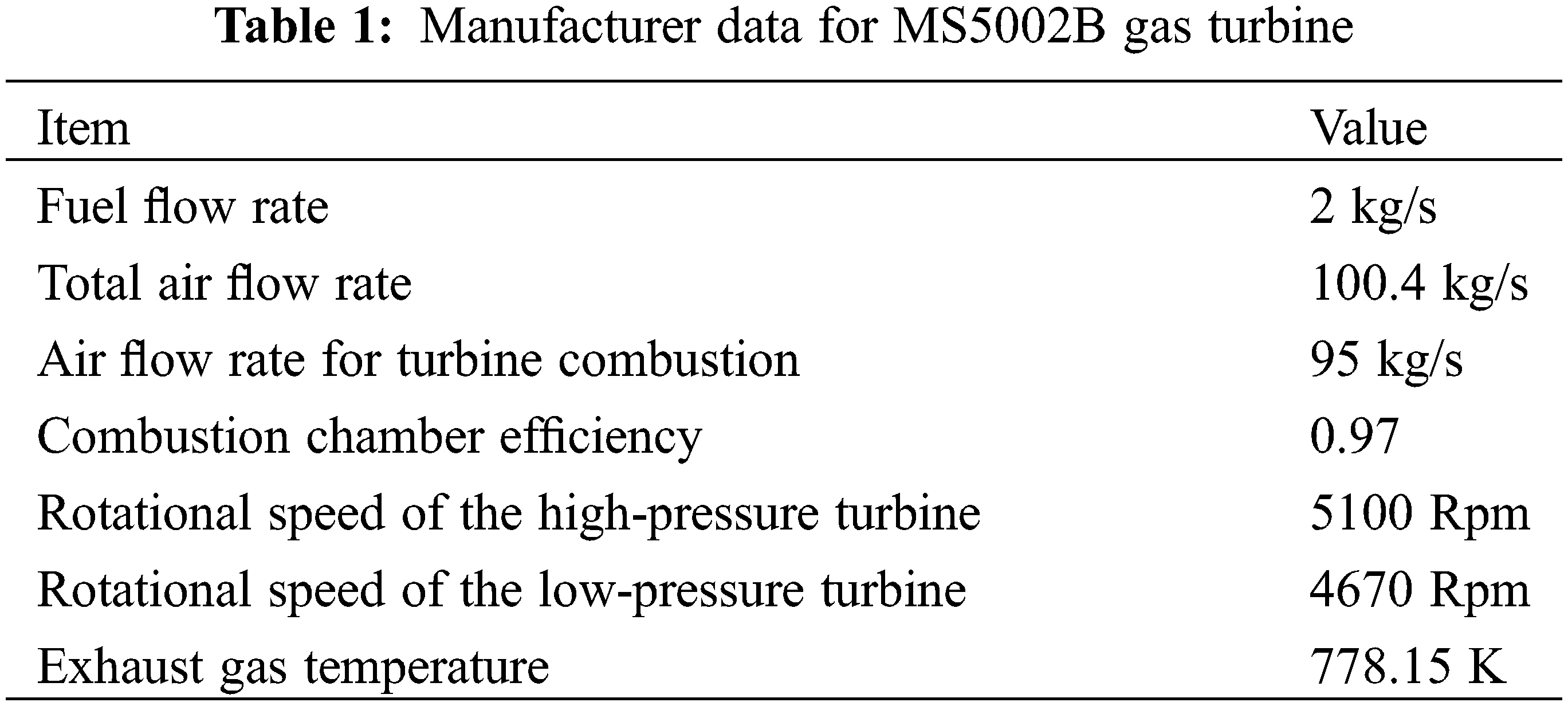
In Fig. 5, the dynamic variation of the inlet temperature throughout the year, particularly during daytime, is presented, featuring two distinctive curves. The black curve illustrates the temperature profile when the cooling system is actively employed, while the red curve depicts the scenario where no cooling system is in operation. Notably, the red curve is derived from data collected at the wing level where the gas turbine is situated, originating from the TAG control room.
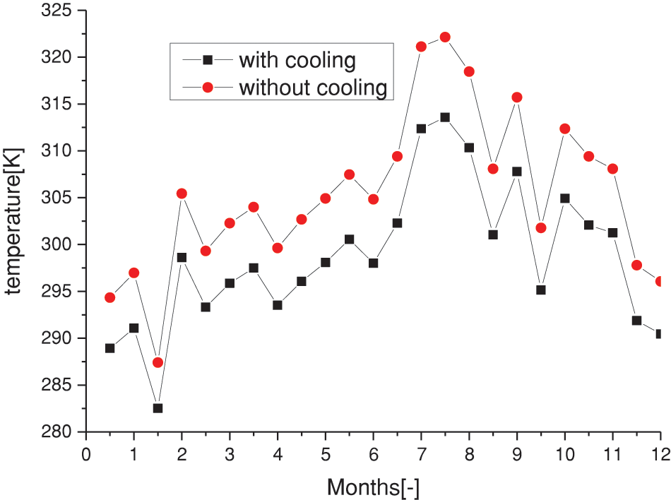
Figure 5: Modeling result showing the variation of the intake temperature with and without intake air cooling
The graph vividly demonstrates elevated temperatures during the summer months, with expectations surpassing 45 degrees and falling below 15 degrees (ISO temperature) solely within the initial two months of the year. This unequivocally underscores the imperative to implement air cooling mechanisms. Subsequently, the black curve showcases the TAG inlet temperature variation when utilizing an evaporative cooler. This cooling system proves effective in reducing the temperature, consequently lowering the specific pressure work.
The widening gap between the two curves, especially during periods of elevated ambient temperatures, signifies the heightened efficiency of the cooling system in warmer climates. Remarkably, the cooling system succeeds in reducing the temperature by 6 to 8 degrees, presenting a tangible contrast between scenarios with and without cooling. This observation further accentuates the efficacy of the evaporative cooler in mitigating the adverse impact of high ambient temperatures on the gas turbine’s performance.
The mass flow rate of incoming air is a critical factor that exhibits variability contingent upon its density. It is noteworthy that this flow rate manifests an inverse relationship with ambient temperature, being lower during high-temperature conditions such as in the summer. This phenomenon arises due to the inherent dependence of air density on temperature.
Examining Fig. 6, the implemented cooling system introduces a significant modification to the air intake process. This system facilitates the controlled evaporation of water into the air, resulting in a perceptibly lower intake temperature when compared to the conventional scenario without cooling. As a consequence, the cooling system contributes to an improvement in mass flow rate dynamics, showcasing a notable increase of 3 percent in comparison to the standard case where no cooling is applied.
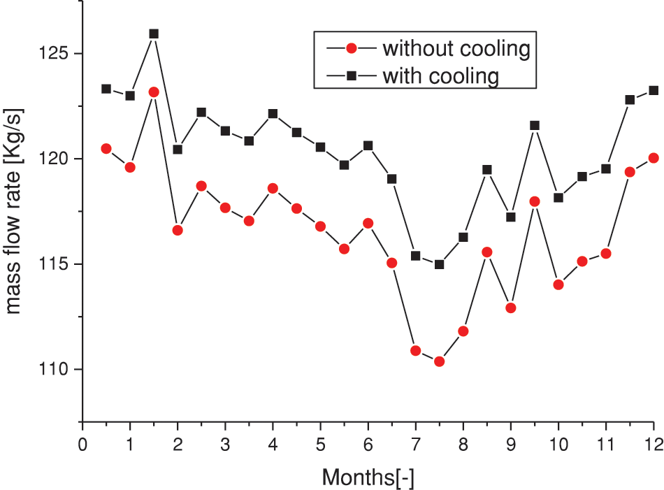
Figure 6: Modeling result showing the variation of the intake air mass flow with and without intake air cooling
This augmentation in mass flow rate is a noteworthy outcome, signifying the positive impact of the cooling system on the gas turbine’s air intake conditions. By effectively mitigating the adverse effects of high ambient temperatures, the cooling system demonstrates its efficacy in optimizing the density and mass flow rate of incoming air. Such enhancements are instrumental in fostering improved performance and efficiency within the gas turbine system, underscoring the importance of employing advanced cooling mechanisms in mitigating temperature-induced limitations.
Fig. 7 provides a comprehensive illustration of the tangible benefits derived from the applied cooling system, specifically in terms of the reduced power consumption of gas turbines. The data presented in the graph highlights a significant reduction, quantified at 10 percent, when compared to the standard case where refrigeration is not employed.
Figure 7: Modeling results showing the variation of power with and without intake air cooling
It is important to note that these results are obtained through numerical simulations of the turbine intlet system, which take into account various factors such as ambient temperature, humidity, turbine characteristics, and the impact of the cooling system on air intake conditions. The numerical simulations provide a detailed understanding of how the cooling system influences the power consumption of the gas turbine under different operating conditions.
This substantial decrease in power consumption, as depicted in Fig. 7, is a noteworthy and consequential result, underscoring the positive impact of the cooling system on the air intake conditions within gas turbines. The 10 percent reduction in power consumption signifies a remarkable improvement in operational efficiency facilitated by the cooling system.
Furthermore, the numerical simulations allow for a comprehensive analysis of the performance enhancements achieved through the implementation of the cooling system. By accurately modeling the interactions between the cooling system and the turbine, the simulations provide insights into the underlying mechanisms driving the observed reduction in power consumption.
This outcome is particularly crucial in enhancing the overall performance of gas turbines, as it directly translates to a more economical and resource-efficient operation. The positive effect observed in reduced power consumption further accentuates the pivotal role of advanced cooling mechanisms in mitigating the adverse effects of high ambient temperatures, ultimately contributing to an optimized and more sustainable gas turbine operation.
In summary, the findings presented in Fig. 7 underscore the significant advantages brought about by the applied cooling system, establishing it as a valuable asset in improving air intake conditions for gas turbines and, consequently, enhancing their operational efficiency. The integration of numerical simulations in this analysis provides a robust foundation for understanding the complex dynamics of gas turbine performance under different cooling scenarios.
In Table 2, the power performance of the water trickle cooler (study case) was compared with that of the absorption chiller [13]. Despite the absorption chiller demonstrating higher capacity, the study suggests that in arid regions, the water trickle cooler may be a more feasible option due to water scarcity. This preference is attributed to the water trickle cooler’s lower water consumption relative to the absorption chiller, as well as its evaporative cooling mechanism, which helps mitigate corrosion risks associated with increased water contact with compressor inlet walls in absorption chillers.
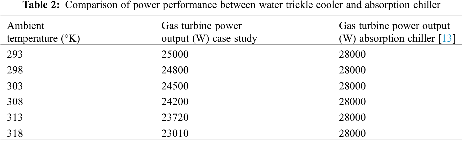
Fig. 8 provides a comprehensive depiction of the noteworthy increase in productivity achieved through the implementation of the cooling system in gas turbines, as opposed to the standard case where cooling is omitted. The data illustrated in the graph vividly highlights the substantial improvement in productivity, emphasizing the pivotal role of the cooling system in optimizing the operational performance of gas turbines.
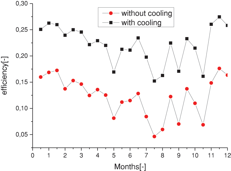
Figure 8: Turbine efficiency with and without cooling
Numerical simulations of the turbine inlet system play a crucial role in understanding the underlying mechanisms driving the observed increase in productivity. These simulations take into account various factors such as inlet temperature, air density, turbine characteristics, and the impact of the cooling system on turbine performance. By accurately modeling the interactions between the cooling system and the turbine, the simulations provide valuable insights into the enhancements achieved in productivity metrics.
This increase in productivity, as depicted in Fig. 8, stands as a key outcome, showcasing the tangible benefits conferred by the cooling system. The comparison with the standard case, where no cooling is applied, serves to underscore the significance of advanced cooling mechanisms in enhancing overall efficiency and productivity in gas turbine operations.
Furthermore, the findings presented in Fig. 8 contribute valuable insights into the positive impact of the cooling system on productivity metrics, providing a basis for informed decisions and advancements in gas turbine technology. By quantifying the increase in productivity achieved through the implementation of the cooling system, the results presented in Fig. 8 contribute to a deeper understanding of the operational benefits associated with advanced cooling mechanisms.
In essence, the results depicted in Fig. 8 underscore the instrumental role of the cooling system in elevating productivity levels within gas turbines, ultimately fostering more efficient and effective energy generation. The integration of numerical simulations in this analysis provides a robust foundation for understanding the complex dynamics of gas turbine performance under different cooling scenarios, paving the way for enhanced operational strategies and improved performance in the realm of power generation.
In conclusion, our comprehensive study has provided valuable insights into the dynamic interplay between ambient temperature, intake air mass flow rate, power, and efficiency in a gas turbine system, with a particular focus on the impact of cooling mechanisms. By comparing scenarios with and without cooling, we have elucidated the effects of cooling on overall operational efficiency.
Firstly, our analysis demonstrates that the cooling system effectively reduces the intake air temperature by 6 to 8 degrees Celsius. This reduction in temperature is crucial for enhancing turbine performance, as cooler intake air leads to improved combustion efficiency and reduced thermal stress on turbine components.
Furthermore, the cooling system contributes to an enhancement in mass flow rate dynamics, showcasing a notable increase of 3 percent compared to the standard case where no cooling is applied. This increase in mass flow rate indicates improved air delivery to the turbine, resulting in enhanced power generation capacity.
In terms of power consumption, our study reveals a significant reduction of 10 percent in gas turbine power consumption when the cooling system is implemented. This reduction in power consumption is attributed to the lower temperature of the intake air, which requires less energy for compression and combustion processes.
Lastly, the cooling system demonstrates a remarkable increase of 10 percent in turbine efficiency compared to the standard case without cooling. This improvement in turbine efficiency underscores the effectiveness of the cooling system in optimizing overall gas turbine performance.
In summary, our findings highlight the significant benefits of employing a cooling system in gas turbine operations. By reducing intake air temperature, improving mass flow rate dynamics, reducing power consumption, and enhancing turbine efficiency, the cooling system plays a pivotal role in enhancing the overall efficiency and performance of gas turbine systems.
Acknowledgement: None.
Funding Statement: The author received no specific funding for this study.
Availability of Data and Materials: All the data used in the study are included in the manuscript.
Conflicts of Interest: The author declares that he has no conflicts of interest to report regarding the present study.
References
1. Farzaneh-Gord M, Deymi-Dashtebayaz M. Effect of various inlet air cooling methods on gas turbine performance. Energy. 2011;36:1196–205. doi:10.1016/j.energy.2010.11.027. [Google Scholar] [CrossRef]
2. Nematollahi M, Porkhial S, Hassanabad MG. Using two novel integrated systems to cool the air toward the ISO condition at the gas turbine inlet. Energy. 2022;243(2):122724. doi:10.1016/j.energy.2021.122724. [Google Scholar] [CrossRef]
3. Naeim KA, Hegazi AA, Awad MM, El-Emam SH. Inlet air fogging strategy using natural gas fuel cooling potential for gas turbine power plants. Case Stud Therm Eng. 2022;37(4):102235. doi:10.1016/j.csite.2022.102235. [Google Scholar] [CrossRef]
4. Cha SH, Na SI, Lee YH, Kim MS. Thermodynamic analysis of a gas turbine inlet air cooling and recovering system in gas turbine and CO2 combined cycle using cold energy from LNG terminal. Energy Convers Manag. 2021;230(7):113802. doi:10.1016/j.enconman.2020.113802. [Google Scholar] [CrossRef]
5. Moradì A, Masoomi M, Salehi GR, Manesh MHK. Performance analysis of gas turbine inlet air cooling plant with hybrid indirect evaporative cooling and absorption chiller system. Int J Thermodyn. 2021;24(3):248–59. doi:10.5541/ijot.840496. [Google Scholar] [CrossRef]
6. Kakaras E, Doukelis A, Prelipceanu A, Karellas S. Inlet air cooling methods for gas turbine based power plants. J Eng Gas Turbine Power. 2017;128(2):312–7. doi:10.1115/1.2131888. [Google Scholar] [CrossRef]
7. Arabi SM, Ghadamian H, Aminy M, Ozgoli AH, Ahmadi B, Khodsiani M. The energy analysis of GE-F5 gas turbines inlet air-cooling systems by the off-design method. Meas Control. 2019;52(9–10):1489–98. [Google Scholar]
8. Santos AP, Andrade CR. Analysis of gas turbine performance with inlet air cooling techniques applied to Brazilian sites. J Aerosp Technol Manag. 2012;4(3):341–54. [Google Scholar]
9. Bin-Shams M, Elkanzi EM, Ramadhan Z, Rahma S, Khamis M. Gas turbine inlet air cooling system for enhancing propane recovery in a gas plant: theoretical and cost analyses. J Nat Gas Sci Eng. 2017;43:22–32. [Google Scholar]
10. Deymi-Dashtebayaz M, Kazemiani P. Energy, exergy, economic, and Environmental analysis for various inlet air cooling methods on Shahid Hashemi-Nezhad gas turbines refinery. Exergy. 2019;30(3):481–98. [Google Scholar]
11. Pourhedayat S, Hu E, Chen L. A comparative and critical review on gas turbine intake air pre-cooling strategies. Therm Sci Eng Prog. 2023;41(1):101828. [Google Scholar]
12. Matjanov E. Gas turbine efficiency enhancement using absorption chiller. Case study for Tashkent CHP gas turbine efficiency enhancement using absorption chiller. Case study for Tashkent CHP. Energy. 2019;192(7):116625. doi:10.1016/j.energy.2019.116625. [Google Scholar] [CrossRef]
13. Marzouk A, Hanafi A. Thermo-economic analysis of inlet air cooling in gas turbine plants. J Power Technol. 2013;93(2):90–9. [Google Scholar]
14. AL-Hamdan OR, Saker AA. Studying the role played by evaporative cooler on the performance of GE gas turbine existed in Shuaiba North electric generator power plant. Energy Power Eng. 2013;5(6):35707. doi:10.4236/epe.2013.56041. [Google Scholar] [CrossRef]
15. Cabarcas MES, Bedoya Villegas JA, Sierra Aragón ÁD, Rodríguez Roldán I, Álvarez Silva DA, Mesa J, et al. Enhancing gas turbine power plant performance in tropical climates by using inlet air cooling with desiccant dehumidification and evaporative cooling. J Therm Sci Eng Appl. 2024;16(1):011006. doi:10.1115/1.4063679. [Google Scholar] [CrossRef]
16. Yu Z, Løvås T, Konovalov D, Trushliakov E, Radchenko M, Kobalava H, et al. Investigation of thermopressor with incomplete evaporation for gas turbine intercooling systems. Energies. 2022;16(1):20. doi:10.3390/en16010020. [Google Scholar] [CrossRef]
17. Bunker RS. Innovative gas turbine cooling technigues. In: IT Transactions on State of the Art in Science and Engineering; 2008. vol. 42, p. 199–229. doi:10.2495/978-1-84564-062-0/07. [Google Scholar] [CrossRef]
18. Dinindu RK. Effect of cooling charge air on the gas turbine performance and feasibility of using absorption refrigeration in the ‘‘Kelanitissa” power station Sri Lanka. Stockholm: KTH Industrial Engineering and Management; 2014. [Google Scholar]
19. Gopinath V, Navaneethakrishnan G. Performance evaluation of gas turbine by reducing the inlet air temperature. Int J Tech Enhanc Emerg Eng Res. 2013;1(1):20–4. [Google Scholar]
20. Didi-Asmara S, Mohd-Amin AM, Adzuieen N. Study on turbine inlet air cooling by chilled water from steam absorption chiller. ARPN J Eng Appl Sci. 2018;13(15):4453–7. [Google Scholar]
21. Ghanaatpisheh M, Pakaein M. Optimization and increase production and efficiency of gas turbines GE-F9 using Media evaporative cooler in Fars combined cycle power plant. Int J Smart Electr Eng. 2015;4(4):211–8. doi:10.1109/IPSC.2015.7827755. [Google Scholar] [CrossRef]
22. Alok KM, Sanjay. Analysis of parameters affecting the performance of gas turbines and combined cycle plants with vapor absorption inlet air cooling. Int J Energy Res. 2014;38(2):223–40. doi:10.1002/er.3046. [Google Scholar] [CrossRef]
23. Sakhaei SA, Safari M. Study and comparison of inlet air cooling technique of gas turbines and their effects on increase of the efficiency and outlet power. Int J Mater, Mech Manuf. 2014;2(4):329–34. doi:10.7763/IJMMM.2014.V2.151. [Google Scholar] [CrossRef]
24. Suneetha S, Satyanarayana AV. Enhancement of specific power output of a gas turbine using filtered chilled air. IOSR J Mech Civil Eng. 2013;7(6):33–6. [Google Scholar]
25. Block-Novelo DA, Igie U, Prakash V, Szymański A. Experimental investigation of gas turbine compressor water injection for NOx emission reductions. Energy. 2019;176:235–48. [Google Scholar]
26. Goucem M, Khiri R. Optimizing supersonic rocket efficiency: a numerical analysis of aerodynamic characteristics and angle of canard deflection. Int Rev Aerosp Eng. 2023;16(5):207–14. [Google Scholar]
Cite This Article
 Copyright © 2024 The Author(s). Published by Tech Science Press.
This work is licensed under a Creative Commons Attribution 4.0 International License , which permits unrestricted use, distribution, and reproduction in any medium, provided the original work is properly cited.
 Downloads
 Citation Tools