
 Submit a Paper
 Propose a Special lssue
 Open Access
ARTICLE

The Disintegration of a Floating Ferrofluid Layer into an Ordered Drop System in a Vertical Magnetic Field
1 Laboratory of Dispersed System Dynamics, Institute of Continuous Media Mechanics UrB RAS, Perm, 614018, Russia
2 Laboratory of Hydrodynamical Stability, Institute of Continuous Media Mechanics UrB RAS, Perm, 614018, Russia
3 Laboratory of Turbulence, Institute of Continuous Media Mechanics UrB RAS, Perm, 614018, Russia
* Corresponding Author: Christina Khokhryakova. Email:
(This article belongs to the Special Issue: Advanced Problems in Fluid Mechanics)
Fluid Dynamics & Materials Processing 2024, 20(10), 2205-2218. https://doi.org/10.32604/fdmp.2024.051053
Received 26 February 2024; Accepted 13 June 2024; Issue published 23 September 2024
 View Full Text
 Download PDF
Abstract
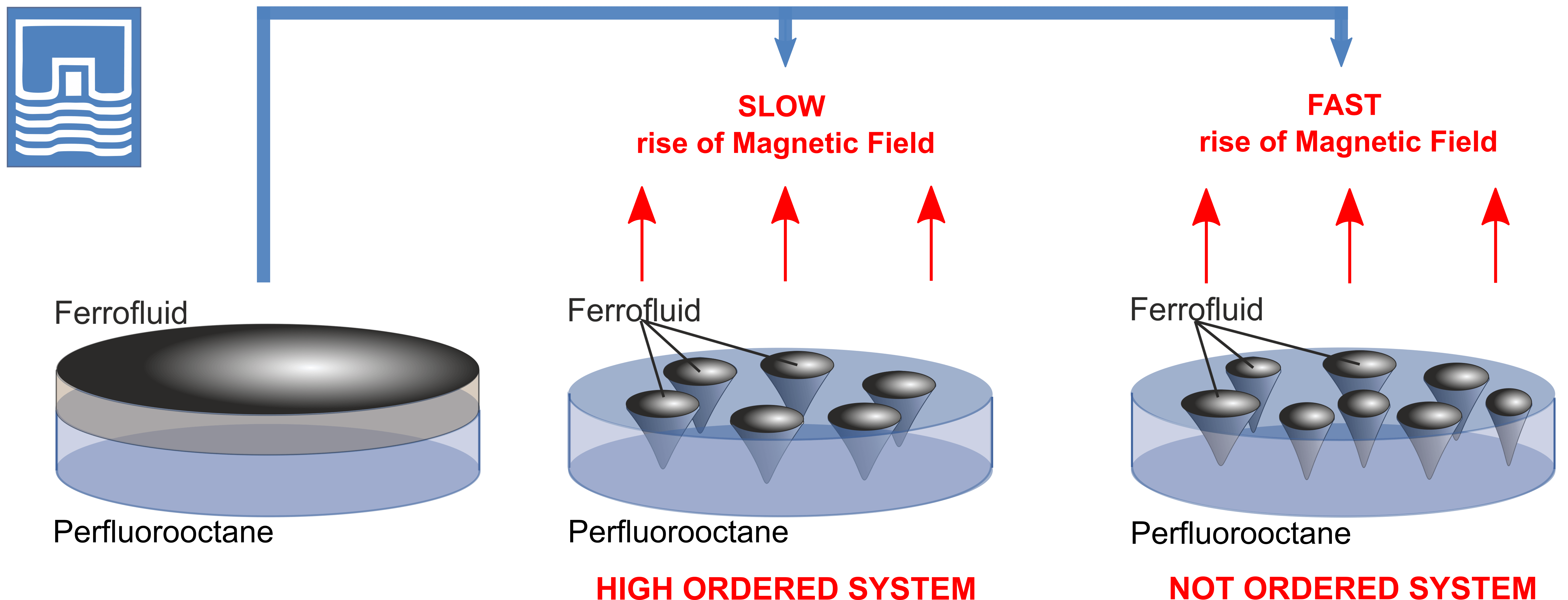
Magnetic fluids, also known as ferrofluids, are versatile functional materials with a wide range of applications. These applications span from industrial uses such as vacuum seals, actuators, and acoustic devices to medical uses, including serving as contrast agents for magnetic resonance imaging (MRI), delivering medications to specific locations within the body, and magnetic hyperthermia for cancer treatment. The use of a non-wettable immiscible liquid substrate to support a layer of magnetic fluid opens up new possibilities for studying various fluid flows and related instabilities in multi-phase systems with both a free surface and an interface. The presence of two deformable boundaries within a ferrofluid layer significantly reduces the critical magnetic field strength required to transform the layer into an organized system of drops or polygonal figures evolving according to the intensity, frequency and direction of the considered magnetic field. This paper experimentally investigates this problem by assuming a uniform magnetic field perpendicular to the surface. This specific subject has not been previously explored experimentally. The critical magnetic field intensity required to destabilize the ferrofluid layer is determined based on the layer’s thickness and the fluid’s initial magnetic susceptibility. It is demonstrated that the critical magnetic field strength needed to disrupt the initially continuous ferrofluid layer increases with the layer’s thickness. Conversely, an increase in the ferrofluid’s magnetic susceptibility results in a decrease in the critical magnetic field strength. The emerging droplet structures are analyzed in terms of the number of drops, their size, and the periodicity of their arrangement. The number of droplets formed depends on the initial thickness of the layer, the presence or absence of a stable rupture in the upper layer, and the rate at which the magnetic field strength is increased to the critical value. A characteristic viscous time is proposed to evaluate the decomposition of the ferrofluid layer, which depends on the duration of the magnetic field’s application. The experimental data on the instability of a ferrofluid layer on a liquid substrate are compared with the theoretical results from the study of “magnetic fluid sandwich structures” conducted by Rannacher and Engel. This comparison highlights the similarities and differences between experimental observations and theoretical predictions, providing a deeper understanding of the behavior of ferrofluid layers under the influence of magnetic fields.Graphic Abstract
Keywords
The instability of a magnetic fluid (or ferrofluid) free surface in an external magnetic field is one of the most striking manifestations of its specific properties [1,2]. When a critical value of the magnetic field component orthogonal to the free surface is reached, the latter becomes unstable with respect to small perturbations [3] that case the deformation of the surface. The instability manifests itself in the form of an ordered system of conical peaks called the “Rosenzweig flower” in honor of the discoverer of this phenomenon [4].
The emergence of such a system is explained by the fact that upon deformation of the surface, the intrinsic (demagnetizing) field of the ferrofluid (FF) decreases under the peaks, and increases near the troughs. Therefore, the total field strength, determined by the action of third-party sources and fluids, increases under the peaks and decreases near the valleys. As a result, the magnetic fluid flows into the region of the magnetic field at higher intensity [5], and an ordered system of conical peaks [4] arises.
The Rosenzweig instability of a ferrofluid layer on a solid substrate under the action of a uniform orthogonal magnetic field has been studied extensively both theoretically [6,7] and experimentally [8,9]. A system of peaks in the form of a hexagonal or square spatial structure [10,11] is quite typical for that case. The peak’s height and shape are determined by the equality of the three pressures: magnetic on the one hand and hydrostatic and capillary on the other. Similar spatial structures were observed in the experiments of disintegration of magnetic fluid thin films (≤50 μm) on a solid substrate [12] or inside some volume of immiscible liquid [13] as well as on the surface of a denser immiscible liquid [14].
The influence of a vertical magnetic field on thick (≥3 mm) layers of magnetic fluid, lying on a solid substrate, is usually limited to the formation of hexagonal relief or a system of parallel edges [15,16] on the free surface. The use of a liquid substrate for such layers would allow them to deform simultaneously from both sides until disintegration into droplets. Experimental results of applying a vertical magnetic field to a ferrofluid located on top of a heavier liquid layer or under a layer of a lighter nonmagnetic immiscible liquid (water) were described in [4]. Due to the instability, a system of ferrofluid peaks penetrating a layer of a nonmagnetic fluid in contact formed. The study was significantly complicated due to the opacity of some of the liquids used in the experiment. A similar effect was observed in a system of a thin film of magnetic fluid on an organic basis on the surface of water in an open glass and turning on a field perpendicular to the surface [17]. The process of the film disintegration was facilitated by the liquid substrate and was accompanied by intense repulsion of the emerging droplets with their splashing out of the glass.
Thus the stability of a magnetic fluid layer in an external magnetic field was studied since the time of Rosenzweig’s research, giving rise to the works of the 90- and 80-s years. The formulation of this problem under new conditions still remains relevant, as shown in the introduction to this article. The problem of instability of a finite-thickness magnetic fluid layer, surrounded by a liquid medium and, accordingly, having freely deformable boundaries, was considered in [18] theoretically. A dispersion equation was obtained for wave disturbances in the linear approximation, and the conditions for instability were described as a function of the density and surface tension of the contacting medium. The problem was solved in two statements: an FF layer bounded by a solid surface and air (classical Rosenzweig instability), and an FF layer with two free surfaces. It has been experimentally shown in [19] that in an orthogonal magnetic field, the interface boundary instability develops when a layer of magnetic fluid is located above a nonmagnetic one. Note that in this work, the ferrofluid layer instability was not accompanied by its disintegration into separate structures. In [4], the observation was made from the upper, free surface of the layer; therefore, the study of the evolution of the interfacial topography was significantly complicated.
An extension of the thickness range of the magnetic fluid layer destroyed by a vertical uniform magnetic field was studied in a theoretical work [20], in which a horizontal ferrofluid layer, placed between two non-magnetic fluids, is considered, forming a so-called “sandwich structure.” A linear and weakly-nonlinear analysis of the instability of such a structure showed that the energy of the system is minimal at a certain amplitude of perturbations of both interfacial surfaces of the FF layer. As a result, the magnetic fluid layer was destroyed and formed a structure of individual droplets. Using the parameters of real liquids, the layer thickness and magnetic field strength were estimated to reach the described effect in the experiment. Such a problem has not been considered anywhere before neither theoretically nor experimentally.
The aim of the work is to study for the first time experimentally the decomposition of FF layer on a liquid non-wettable substrate in an orthogonal uniform magnetic field, to analyze the resulting drop structures, and to compare data obtained with the results of theoretical work [20]. The preliminary results of the study were presented in [21].
In the experiment, we used three kerosene-base ferromagnetic fluids, stabilized by oleic acid, hereinafter called FF 1, FF 2 and FF 3, prepared by the standard chemical precipitation method at AO NIPIgazpererabotka (Krasnodar, Russia) [22]. The FFs have equal density but different initial magnetic susceptibility due to the particle sizes (magnetic core average diameter <d>), their average magnetic moment <m> and concentration n. The magneto-granulometric analysis [23] was utilized to estimate the magnetic properties of the ferrofluids, which were measured with the help of the differential magnetic sweep method [24]. For the qualitative analysis of experimental findings presented in this paper, the initial magnetic susceptibility was used to characterize the ferrofluid magnetic response to the external magnetic action in the range of weak field intensities, according to the magnetization curve. In the case of simulation or quantitative analysis, one needs to estimate the problem in the so-called inductive approximation [25–27].
Due to its high density and low surface tension [28], perfluorooctane C8F18 was chosen as a liquid substrate for the ferrofluid layer. Physico-chemical properties of liquids of the layer and the substrate used in the experiment are presented in Table 1.
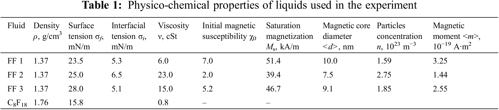
Here surface tension measurements were conducted with the help of tensiometer Sigma 701 K100 (Biolin Scientific, Gothenburg, Sweden) by the du Noy ring method (Δσ = ±0.1 mN/m) [29]. Kinematic viscosity ν was calculated from the dynamic one ν = η/ρ measured with Rotational Viscosimeter (AMETEK Brookfield, Middleborough, MA, USA) (Δν = ±0.1 cSt). The density measurement error was Δρ = ±0.01 g/cm3.
The experimental setup is shown in Fig. 1. The liquid system filled the cuvette 3 in the form of a short vertical glass cylinder with diameters D1 = 59.4 mm and D2 = 89.0 mm. During the experiment the cuvette was covered by a glass to prevent the kerosene evaporation. The thickness of the ferrofluid layer 2 was defined as h = m/ρ2S, where m is the fluid mass, S is the area of the cuvette, D is the inner diameter of the cuvette. The fluid mass and, accordingly, the layer thickness were determined by weighing a syringe with the ferrofluid on an electronic scale (OKB VeSta, St. Petersburg, Russia) before and after its injection into the cuvette. Thus, the ferrofluid layer thickness h varied from 1 to 4 mm. The thickness of liquid substrate 1 was several times thicker than the ferrofluid layer, varying, respectively, from 10 to 25 mm. The accuracy of the layers’ thickness measurement was about 0.1 mm.
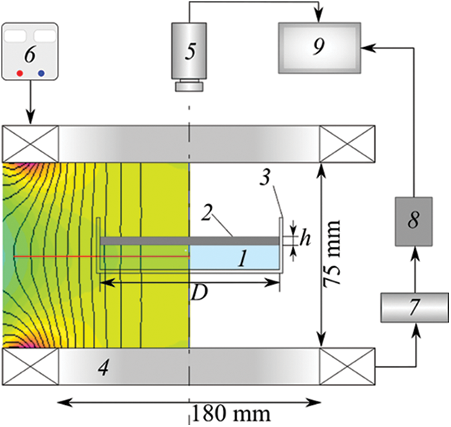
Figure 1: Experimental setup: 1–liquid substrate (perfluorooctane); 2–ferrofluid; 3–a glass cuvette filled with a two-layer fluid system; 4–Helmholtz coils; 5–camera; 6–stabilized power supply; 7–resistor; 8–ADC converter; 9–computer. Left part of the figure illustrates the magnetic field distribution inside the Helmholtz coils system gained with the help of FEMM (Finite Element Methods Magnetic) program
In the course of the experiment, the cuvette 3 was placed on a horizontal platform between the vertically oriented Helmholtz coils 4. The symmetry axis of the cuvette coincided with the center of the coils. The Ferrofluid layer and the ordered drops system were recorded by a digital video camera 5 mounted over the Helmholtz coils. The intensity H of the magnetic field generated by the coils was regulated by a stabilized power source 6 of HY3010-2 (Mastech, Hong Kong, China). The value of the current through the coils was controlled with the help of voltage drop across a small resistor 7 connected in series with the coils, which was fed to the input of the analogue-to-digital converter ADC LA-I24 USB (Rudnev-Shilyaev, Moscow, Russia) 8 and processed using the standard software kit.
The relative heterogeneity of the vertical component of the field strength, measured with a Hall-probe sensor at the level of the free surface of continuous (non-deformed) ferrofluid layer along the cell radius, did not exceed 1% for a cuvette with a diameter of D1 and 3% for a cuvette with a diameter of D2. The left part of the Fig. 1 illustrates the magnetic field distribution inside the Helmholtz coils system gained with the help of Finite Element Methods Magnetics software (D.C. Meeker, Waltham, MA, USA) [30]. The experiments were performed at the temperature of the liquid system and the environment of (23 ± 1)°C.
It was shown in [20] that the absence of special damping of the experimental setup created conditions for the occurrence of perturbations of the ferrofluid-free surface and interface in the form of gravitational-capillary waves. The vertical magnetic field enhanced these disturbances and led to the formation of a relief surface in the form of a system of penta-or hexagonal cells on the free surface and interface of the ferrofluid layer, as in the case of a solid substrate [6]. In this case, the deformation of the lower boundary of the layer is significantly higher since the density and the interfacial tension there were three times less than on the free surface, which confirms the conclusions of [20].
A further increase of the field intensity led to a discontinuity of the layer and the formation of an ordered system of individual drops of ferrofluid (Fig. 2a). Compared to the case of a solid substrate, the layer breaks at much lower values of the critical intensity Hi*, since for this it is enough that the total disturbance amplitude of both surfaces of the layer exceeds its thickness.
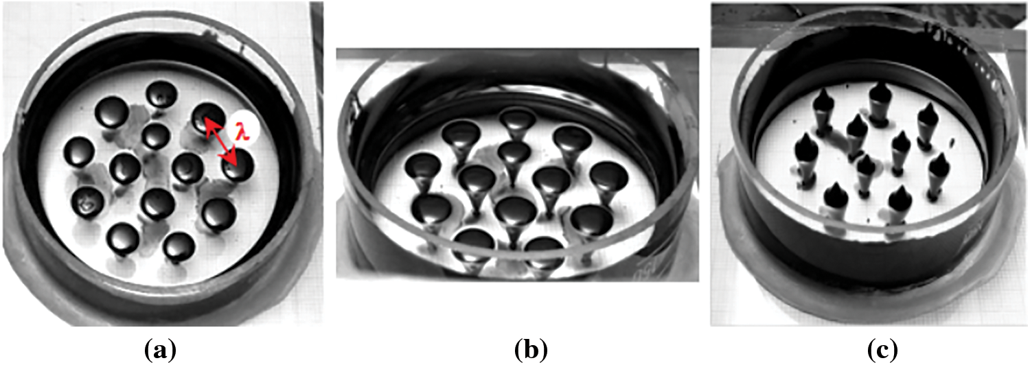
Figure 2: Drop structure resulting from the disintegration of the FF 1 layer under the action of a vertical magnetic field. Initial layer thickness h = 2.7 mm, Hi* = 3.2 kA/m (a, b), Hf* = 4.5 kA/m (c); D1 = 59.4 mm
The droplets align into an ordered structure and had the form of sessile drops at the air-perfluorooctan interface (similar to droplets on a solid surface [31]). Further they transformed into the floating cones immersed in the liquid substrate Fig. 2b. A further increase in the magnetic field intensity induced the droplets stretching along the field into the liquid substrate till they reached the bottom of the cuvette. The critical field intensity Hf* denoted the instability on the free surface of the droplets in the form of peaks that appeared on it in a threshold manner, as in the well-known “Rosenzweig flower” (Fig. 2c).
The results of the experiment show that the critical field strength H* slowly increases with the initial layer thickness (Fig. 3), while the magnetic susceptibility of ferrofluid has a more significant effect. In particular, a threefold increase in magnetic susceptibility causes a decrease in the critical field intensity of about two times [21,24]. Such an effect takes place as the ferrofluid magnetic response on the external magnetic action was assumed in the range of weak field intensities, used in the current experiment that corresponds to the so-called non-inductive approximation realized in [20]. At the same time, the value of H* weakly depends on the diameter of the cuvette, which allows one to compare it with the case of the semi-infinite layer. The critical magnetic field strength H* for the layer of FF 2 on a solid substrate (Fig. 3, 6) is higher than that for the floating layer of FF 2 on perfluorooctan [24,32].
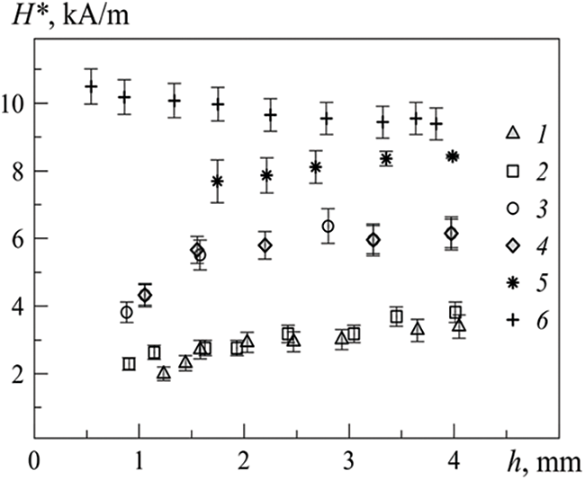
Figure 3: Critical magnetic field strength H* vs. the thickness of the ferrofluid layer h. Initial magnetic susceptibility χ0: 7.0 (1, 2), 5.2 (3, 4), 2.0 (5, 6); cuvette diameter D, mm: 59.4 (1, 3, 5, 6), 89.0 (2, 4); layer of FF 2 on a liquid substrate (5), layer of FF 2 on a solid substrate (6)
It should be noted that the average diameter of the droplets practically does not depend on the variations in the initial layer thickness. At the same time, an increase in the layer thickness leads to an increase in both the number of emerging drops and the threshold intensity Hf*. This dependence could be explained by the change in the structure of the additional magnetic field caused by a decrease in the distance between the drops due to an increase in their quantity with an increase in the layer thickness.
This fact is confirmed by a comparison of the values of the threshold intensity Hf* for drops in the system and single drops of ferrofluid of the same size floating on the free surface of perfluorooctane [33] (Fig. 4). The droplets sizes were determined from their diameter when viewed from above in zero magnetic field. In the absence of the magnetic field, the drop spreads uniformly over the surface of the C8F18, forming an ellipsoid with two asymmetric lateral surfaces: free surface and interface. The conditions for the spreading of a ferrofluid droplet over the C8F18 surface in zero field are the same for droplets in the system and for single droplet. With an increase of the field strength, the diameter of the droplets gradually decreased, since their volume was redistributed between the upper and lower parts relative to the interface. Based on the data obtained in the study of the behavior of a single drop in a magnetic field [33], we compared the horizontal dimensions of a drop in the system and a single drop at a given field strength. Using these data, the horizontal sizes of droplets in the system were obtained at zero field.
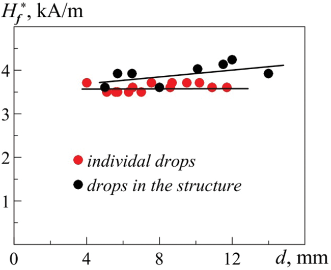
Figure 4: Critical magnetic field intensity Hf* via the drops initial diameter measured in the absence of the magnetic field for individual drops and for the drops in the ordered structure, resulting from the disintegration of a horizontal FF 1 layer of a thickness h = 1.47 mm
To test this technique, we compared the horizontal sizes of droplets in the system in a magnetic field for a sufficiently thin ruptured FF layer. To this end, samples of FF drop of various diameters were taken from the droplet system with the help of a medical syringe and weighed using an analytical balance with an accuracy of 0.01 g. The diameters of drop were determined with an accuracy of 0.5 mm, which, however, does not affect the general form of the dependence Hf*(d0). The accuracy for the critical magnetic field intensity Hf* measurement was in the same range for the corresponding ferrofluid as depicted in Fig. 3.
The reverse decrease in the strength of the applied magnetic field leads to a decrease in the deformation of the drop and then to the closure of the ferrofluid layer. In Fig. 5, the dependence of the horizontal diameter d of a ferrofluid droplet, formed as a result of layer rupture, on the magnitude of the magnetic field is shown. The dependence has a hysteretic character since the layer closure occurs at a significantly lower field strength than at its break. The reason for the observed phenomenon is that to close the ferrofluid layer rupture, it is necessary to close the free surface of the substrate formed by a liquid with a lower surface tension. The dependence has one more local hysteresis (at H ≈ 4 kA/m), which is associated with the contact of the bottom of the cell with the top of the droplet cone. Touching the bottom also explains the decrease in the rate of decrease in the droplet diameter with a further increase in the field strength.
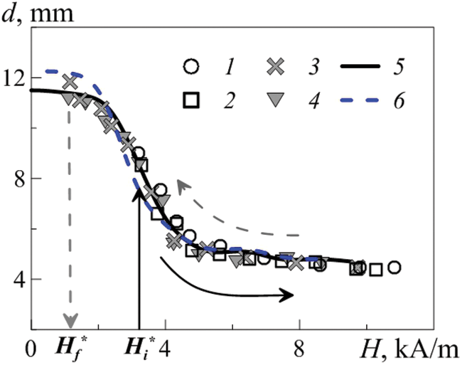
Figure 5: The horizontal diameter d of two droplets of the same size FF 1 ferrofluid obtained at a slowly (1, 3) and rapidly (2, 4) field growing to a critical value, depending on the strength H. Solid arrows show the increase in the field strength from the moment of layer disintegration, the dashed arrows show the decrease in the field strength up to the collapse of the layer. The thickness of the layer being torn off is h = 2.4 mm. Cuvette diameter D2 = 89.0 mm
The experiment showed that the number and size of the emerging drops–in addition to the initial thickness of the ferrofluid layer–is also determined by the time t* of the increase in the magnetic field strength to a critical value (Fig. 6). Such a dependence is explained by the evolution of the spectrum of gravitational-capillary waves existing on the free and interface surfaces of the ferrofluid layer during the time of the field change. As a criterion, we choose the viscous time τ for the ferrofluid layer (
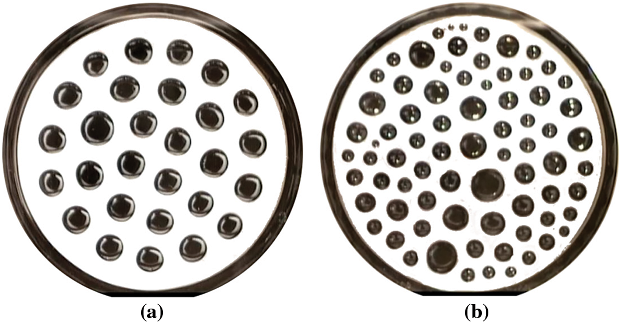
Figure 6: Drop systems, that arise when a ferrofluid layer FF 1 of a thickness h = 2.9 mm disintegrates in a magnetic field H* = 3.7 kА/m: (a) t* = 93 s, τ = 11 s; (b) t* ≤ 1 s, τ = 11 s, obtained in the cuvette with the diameter D = 89.0 mm
In order to explain such behavior, two series of experiments were performed on the layer of constant thickness in a slowly (t* = 93 s, τ = 11 s) (Fig. 6a) and a rapidly (t* ≤ 1 s, τ = 11 s) (Fig. 6b) growing magnetic field. The cumulative data of these experiments were used to construct the droplet size distributions shown in Fig. 7. Every point in the figure was obtained within several experimental realizations. The form of the obtained distributions testifies in favor of the thesis about the role of the magnetic field, which enhances the perturbations existing in the ferrofluid layer–long-wave in the case of a slowly growing field and the entire spectrum of perturbations when it is quickly switched on. It is necessary to point out the noticeably larger volume of the ferrofluid, which passed into the near-wall zone of the cell when the layer is broken in the case of a slowly increasing field.
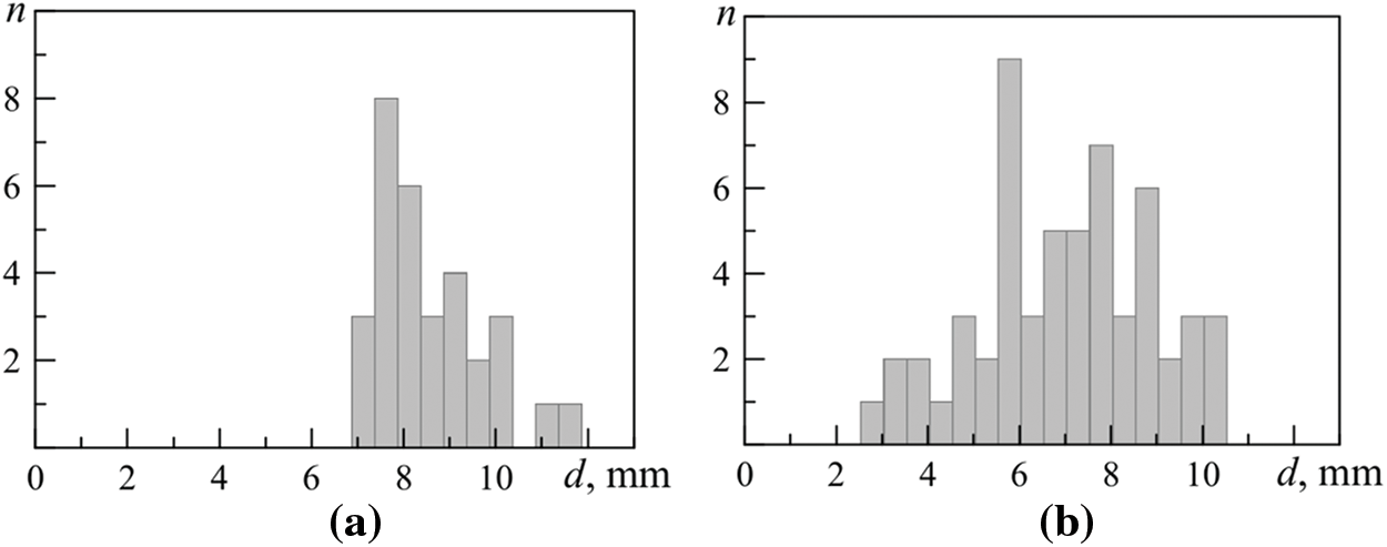
Figure 7: The drop size distributions d(n) when the ferrofluid layer FF 1 of a thickness h = 2.9 mm disintegrates in a magnetic field H* = 3.7 kА/m (according to Fig. 6): (a) t* > τ, (b) t* < τ
Note that in both cases, droplets of medium size predominate. The main role in their formation is played by gravitational-capillary disturbances on one of the layer surfaces, particularly at the interface, as disturbances there have a longer wavelength.
Another issue is related to the finite size of the cuvette, specifically the influence of the annular meniscus formed by the ferrofluid in the near-wall zone when the layer ruptures. The distortion of the magnetic field leads to a radial shift of the droplet system in the direction of the cuvette’s axis (coinciding with the axis of the Helmholtz coils). As a result, the distance between droplets should change compared to the case of infinite layer rupture used in theoretical work. The greatest shift is observed for the droplets being closest to the meniscus. On the contrary, drops located in the center of the drop system should experience the least shift and, accordingly, should be as ordered as possible, that is, at equal distances from each other.
Based on the experimental data, distributions of the spatial period λ of the droplet structure were constructed using original software implemented on Mathematica 8.0 (Wolfram, Champaign, IL, USA) for cases of slow and rapid increases in field strength (Fig. 8). Distances were measured not only between a droplet and its nearest neighbors but also between it and all droplets in each penta-and/or hexagonal structure. The number of identical wavelength values nrel is normalized by the total measured distances n between all droplets in the resulting droplet system.
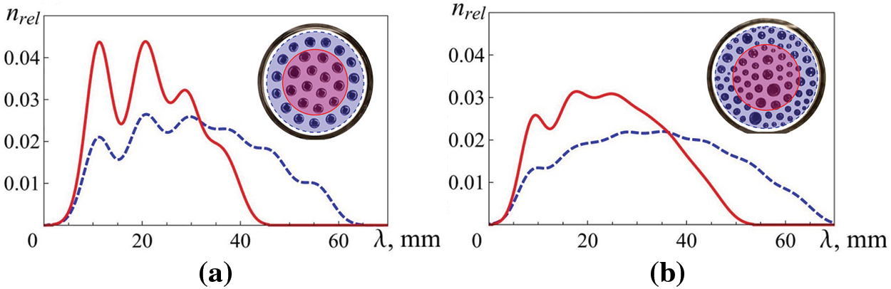
Figure 8: Distribution of spatial periods λ for droplets in the above systems (Fig. 6): the solid line is for drops from the central part of the cuvette, and the dashed line is for all drops in the system: (a) t* > τ, (b) t* < τ
The distribution of the spatial period is shown both for the central part of the cuvette (red solid line) and for the entire droplet structure (blue dotted line). The presence of well-defined maxima on both curves in Fig. 8a, indicates a high degree of order in the system of droplets, resulting from the rupture of the layer with a slow increase in the field. In particular, this confirms the existence of a sixth maximum on the dotted curve, which corresponds to a certain distance even between the extreme diametrically located drops of the system. On the contrary, the degree of ordering of the droplet system that arises with a rapid increase in the field (Fig. 8b) is much less–only the first peak, corresponding to the distance between the nearest droplets, is clearly visible in both curves. Note that the second and third peaks are noticeably higher than the first, indicating the presence in the system of a large number of droplets of different but fairly similar sizes. The absence of even blurred peaks older than the seventh on the dashed curve shows that the region of order is significantly smaller than the size of the droplet system (the number of droplets along the system’s diameter on average reaches nine).
According to the value of the spatial period corresponding to the first maximum in Fig. 8, the wave number of the main surface disturbances was determined, which was later used for comparison with the theoretically calculated values [20].
4 The Analysis of the Experimental Results
The results obtained in this work were compared with similar experimental studies on the instability of a ferrofluid layer. Fig. 9 shows the wave numbers k = 2π/λ of the emerging droplet systems from the initial thickness of the ferrofluid layer on solid and liquid substrates. The dependence of the wave number on the layer thickness (Fig. 9) demonstrates a significant difference in the action of the capillary (thin layer [12]) and capillary-gravitational (layer of finite thickness) mechanisms of perturbation of the ferrofluid surface. The difference in the slope of the k(h) curve is explained by different boundary conditions in the experiments.
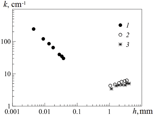
Figure 9: Wave number k vs. the thickness of the ferrofluid layer h located on a solid substrate (1) and on a liquid one for t* < τ (2) and t* > τ (3)
We use the results obtained to verify the outcomes of the theoretical work by Rannacher et al. [20], which explored the deformation of a horizontal ferrofluid layer with finite thickness ℎ, bounded above and below by non-magnetic fluids (see Fig. 1). According to Rannacher et al. [20], we chose field strength and length as units of measurement:
where Hc and kc are, respectively, the critical values of the field strength and the wave number of the Rosenzweig instability for an infinitely deep ferrofluid layer, ρff is the ferrofluid density, ρair is the air density, σh is the surface tension of the free boundary of the ferrofluid layer. This choice allows us to present the experimental data in the form of the critical magnetic field intensity depending on the initial thickness of the ferrofluid layer in dimensionless form (Fig. 10).
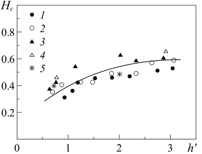
Figure 10: Critical magnetic field strength Hc via the ferrofluid layer thickness h′ = h/λc in dimensionless form. Initial magnetic susceptibility χ0: 2.0 (3, 4), 7.0 (1, 2), 5.2 (5). Cuvettes diameter D, mm: 59.4 (1, 3, 5), 89.0 (2, 4)
For more accurate comparison, Fig. 11 shows the theoretical dependence of the magnetic field strength on the wave number Hс(k), determined for a series of experiments on the rupture of different ferrofluid layers with a thickness of about h = (2.9 ± 0.1) mm. The neutral curve in Fig. 11 was obtained from [20] as a result of minimum condition for the total energy (the sum of hydrostatic, interfacial and magnetic energies) of the ferrofluid layer on a liquid substrate, using physico-chemical properties of fluids used in the experiment (see Table 1). All the experimental points are in good quantitative agreement with the theoretical analysis [20]. Some deviation of experimental points from the theoretical neutral curve is explained by the fact that the thickness of the ruptured layer varied. The physicochemical parameters of the liquids varied somewhat in the course of the experiment, in particular, due to evaporation and very slow diffusion of kerosene from the ferrofluid into perfluorooctane.
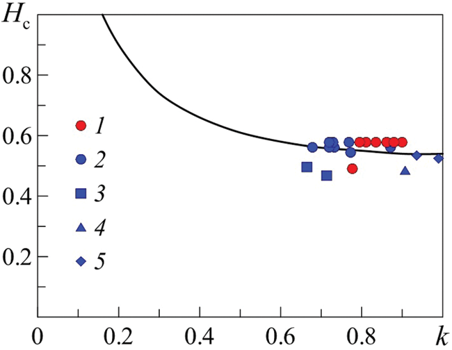
Figure 11: Dimensionless critical magnetic field strength Hc via the wave number kc for the ferrofluid layer with a thickness of h = 2.9 mm at the minimum of total energy. Solid line—neutral curve obtained from the linear stability analisys of [20], dots—experimental data: FF 1—t* > τ, D = 89 mm (1), —t* < τ, D = 89 mm (2); t* > τ, D = 59 mm (3); FF No. 3—t* > τ, D = 59 mm (4); FF 2—t* > τ, D = 59 mm (5)
5 Deformation of a Ferrofluid Layer with a Stable Surface Rupture
In conclusion, let us address the behavior of a two-layer system with an initial rupture of the upper layer d0. Such ruptures, under specific conditions, can persist for an extended period without the support of any external forces [34].
In the range of magnetic field strengths used (H < 12 kA/m), the deformation of ferrofluid layers with χ0 < 2 was limited to the formation of hexagonal surface relief, similar to that described in [15]. However, if such ferrofluid layer has a stationary surface rupture [28], then the influence of the field can lead to the formation of droplet structures. A similar evolution of a layer with a rupture is observed for ferrofluids with a sufficiently large χ0. In both cases, the layer deformation depends on the initial size of the rupture and the diameter of the cuvette.
Thus, in the case of relatively large ruptures (d0 ≥ D/2, see in Fig. 12a), turning on the field causes its diameter to increase due to the displacement of the ferrofluid into the region of the wall meniscus (Fig. 12). A further increase in the field strength leads to the appearance of instability of the meniscus boundary in the form of a “shoot” growing towards the center of the cuvette (Fig. 12b). Then the process breaks off, turning into a “horseshoe”, which, in turn, breaks up into individual drops (Fig. 12c). A decrease in the field strength leads to the reverse merging of droplets until a layer with a stable rupture is formed.
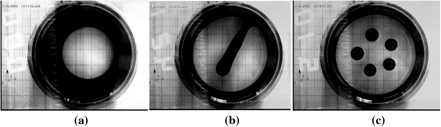
Figure 12: The instability of FF 2 floating layer of thickness h = 2.2 mm with a stable initial rupture of diameter d0 = 34.0 mm in the uniform vertically oriented magnetic field Н, kA/m: 0 (a), 4.4 (b), 5.4 (c). D1 = 59.4 mm
For layers with a stable rupture of relatively small diameter (d0 < D/2, see Fig. 13a) the transition to droplet structures begins with an increase in the rupture diameter by expanding it along the cuvette wall. Along with that some ferrofluid is displaced into the center of the cuvette until a “polygon” there is formed (Fig. 13b). The number of the drops in the “polygon” depends on the ferrofluid’s magnetic susceptibility and the cuvette’s size. A further increase in the field strength leads to the rupture of the “polygon” into individual drop cones. The cones gradually reach the bottom of the cuvette. Next, at a certain value of tension H**, the cones are deformed, each being divided into two parts, the tops of which form peaks (Fig. 13c). Thus, as a result of fission, a decrease in the spatial period of the formed droplets is observed. A further increase in magnetic field strength (up to Н*** = 10.2 kA/m) leads to the instability of the ferrofluid meniscus boundary in the form of a small comb.
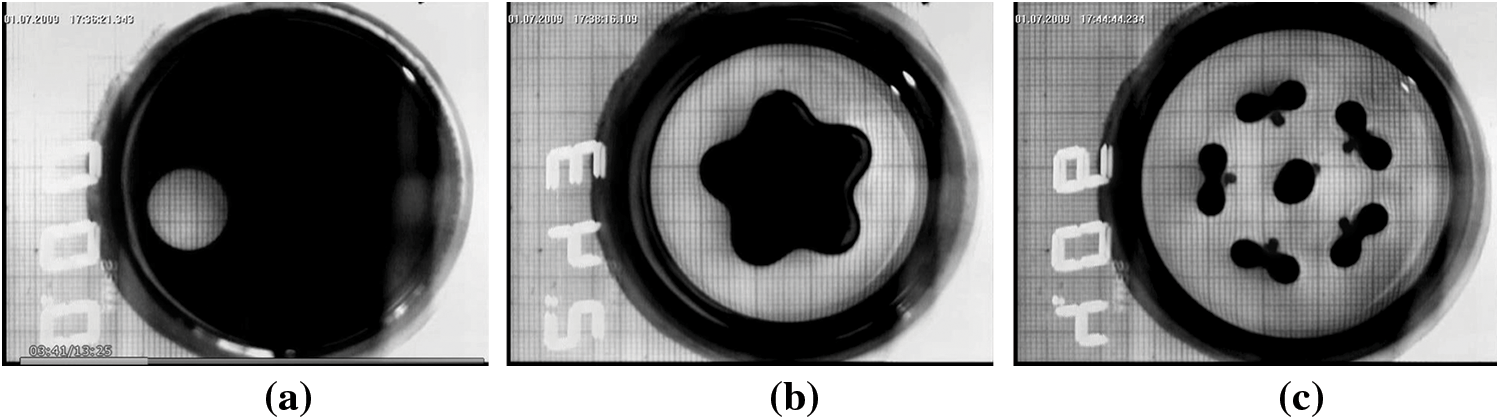
Figure 13: Deformation of ferrofluid FF 1 floating layer of thickness h = 2.7 mm with a stable initial rupture of diameter d0 = 15.4 mm in the uniform vertically oriented magnetic field Н, kA/m: 0 (а); 2.6 (b); 4.3 (c); D1 = 59.4 mm
Comparison with the case of a continuous layer shows that in the presence of a stable rupture, the transition to droplet structures occurs at noticeably lower field strengths. Note that the formation of the structures described above occurs in times comparable to or greater than the viscous times for the ferrofluid layer (t* ≥ τ). In this case, a layer with a stable rupture of large diameter is transformed into a layer with an even larger rupture without the appearance of droplet structures.
The paper presents the results of an experimental study on the floating ferrofluid layer instability in the uniform magnetic field normal to the liquid surface. The use of the liquid substrate facilitates the decay process of such ferrofluid layers, in which deformation on a solid substrate is limited only by periodic disturbance of the surface. A uniform magnetic field causes the formation of an ordered system of droplets, which number depends on the initial thickness of the layer, the presence of a stable rupture, and its size, as well as on the rate of increase in the field strength to a critical value. The magnitude of the critical magnetic field strength leading to the disintegration of the initially continuous layer increases with its thickness. An increase in the ferrofluid magnetic susceptibility leads to a decrease in the critical magnetic field strength. The experimental data obtained for the critical values of the magnetic field strength and the spatial period of the ferrofluid surface instability are in good agreement with the theoretical description of the disintegration of a ferrofluid layer into droplets, developed for the Rannacher “magnetic fluid sandwich structures” [20].
Acknowledgement: The authors of the paper would like to thank A.V. Lebedev for the help with magnetogranulometric analysis of magnetic fluids used in the experiment and A.F. Pshenichnikov for fruitful discussions.
Funding Statement: The work was performed in the framework of the State Program AAAA-A20-120020690030-5.
Author Contributions: The authors confirm contribution to the paper as follows: study conception and design: Christina Khokhryakova, Konstantin Kostarev; data collection: Christina Khokhryakova; experimental data processing: Irina Mizeva; analysis and interpretation of results: Christina Khokhryakova, Konstantin Kostarev; draft manuscript preparation: Christina Khokhryakova; graphical abstract: Irina Mizeva. All authors reviewed the results and approved the final version of the manuscript.
Availability of Data and Materials: The data is available by request.
Conflicts of Interest: The authors declare that they have no conflicts of interest to report regarding the present study.
References
1. Li XF, Wang YP, Zhang YC, He TP, Niu XD, Khan A, et al. On the rosensweig instability of ferrofluid-infused surfaces under a uniform magnetic field. Phys Fluids. 2023;35(11):113306. [Google Scholar]
2. Zhang X, Sun L, Yu Y, Zhao Y. Flexible ferrofluids: design and applications. Adv Mater. 2019;31(51):1903497. [Google Scholar]
3. Gailitis A. A form of surface instability of a ferromagnetic fluid. Magnetohydrodynamics. 1969;5:44–5. [Google Scholar]
4. Cowley MD, Rosensweig RE. The interfacial stability of a ferromagnetic fluid. Jour Fluid Mech. 1967;30(4):671–88. [Google Scholar]
5. Ya BE, Mayorov MM, Cebers AO. Magnetic fluids. Berlin: Walter de Gruyter; 1997. [Google Scholar]
6. Shliomis MI. Magnetic fluids. Sov Phys Usp. 1974;17(2):153. [Google Scholar]
7. Bashtovoi VG. Instability of a stationary thin layer of a magnetizable liquid. J Appl Mech Tech Phys. 1978;19(1):65–9. doi:10.1007/BF00851365. [Google Scholar] [CrossRef]
8. Berkovsky B, Bashtovoi V. Instabilities of magnetic fluids leading to a rupture of continuity. IEEE Trans Magn. 1980;16(2):288–97. doi:10.1109/TMAG.1980.1060613. [Google Scholar] [CrossRef]
9. Bacri JC, Salin D. First-order transition in the instability of a magnetic fluid interface. J Phys Lett. 1984;45(11):559–64. doi:10.1051/jphyslet:019840045011055900. [Google Scholar] [CrossRef]
10. Boudouvis AG, Puchalla JL, Scriven LE, Rosensweig RE. Normal field instability and patterns in pools of ferrofluid. J Magn Magn Mater. 1987;65(2–3):307–10. doi:10.1016/0304-8853(87)90057-6. [Google Scholar] [CrossRef]
11. Abou B, De Surgy GN, Wesfreid JE. Dispersion relation in a ferrofluid layer of any thickness and viscosity in a normal magnetic field; asymptotic regimes. J de Phys. 1997;7(8):1159–71. doi:10.1051/jp2:1997178. [Google Scholar] [CrossRef]
12. Dikansky YI, Zakinyan AR, Mkrtchyan LS. Instability of a thin layer of a magnetic fluid in a perpendicular magnetic field. Tech Phys. 2010;55(9):1270–4. doi:10.1134/S1063784210090069. [Google Scholar] [CrossRef]
13. Chen CY, Li CS. Ordered microdroplet formations of thin ferrofluid layer breakups. Phys Fluids. 2010;22(1):014105. doi:10.1063/1.3298761. [Google Scholar] [CrossRef]
14. Bacri JC, Perzynski R, Salin D. Instability of a ferrofluid film. Comptes Rendus de l’Académie des Sci, Paris. 1988;307:699–704. [Google Scholar]
15. Barkov YD, Bashtovoi VG. Experimental investigation of instability of flat layers of magnetized liquid. Magnetohydrodynamics. 1977;13(4):497–9. [Google Scholar]
16. Richter R, Lange A. Surface instabilities of ferrofluids. Colloid Magn Fluids Basics, Dev App Ferrofluids. 2009;763:157–247. [Google Scholar]
17. Rosensweig RE. Ferrohydrodynamics. New York: Cambridge University Press; 1985. [Google Scholar]
18. Bashtovoi VG. Instability of a thin layer of a magnetic fluid with two free boundaries. Magnetohydrodynamic. 1978;13(3):23–8. [Google Scholar]
19. Bashtovoi VG, Krakov MS, Reks AG. Instability of a flat layer of magnetic liquid for supercritical magnetic fields. Magnetohydrodynamics. 1985;21(1):14–8. [Google Scholar]
20. Rannacher D, Engel A. Double Rosensweig instability in a ferrofluid sandwich structure. Phys Rev E. 2004;69(6):066306. doi:10.1103/PhysRevE.69.066306. [Google Scholar] [PubMed] [CrossRef]
21. Bushueva CA. Drop structures formed by ferrofluid in the uniform magnetic field. Magnetohydrodynamics. 2013;49(3–4):598–602. doi:10.22364/mhd.49.3-4.64. [Google Scholar] [CrossRef]
22. Ivanov AS. On the reasons for reversible aggregation of magnetite ferrofluids during their dilution with a pure carrier in zero magnetic field. Colloid J. 2022;84(6):696–703. doi:10.1134/S1061933X22600257. [Google Scholar] [CrossRef]
23. Pshenichnikov AF, Mekhonoshin VV, Lebedev AV. Magneto-granulometric analysis of concentrated ferrocolloids. J Magn Mater. 1996;161:94–102. doi:10.1016/S0304-8853(96)00067-4. [Google Scholar] [CrossRef]
24. Koskov MA, Lebedev AV, Ivanov AS. About the differential sweep method for measuring of ferrocolloids magnetization curves. Proc Southwest State Univ. Series: Eng Technol. 2023;13(3):89–104 (In Russian). [Google Scholar]
25. Ivanov AS, Khokhryakova CA. Non-magnetic solid body in ferrofluid containers: wall effects. J Phys: Conf Series. 2021;1945(1):012011. [Google Scholar]
26. Ivanov AS. An energy approach to the calculation of forces acting on solid bodies in ferrofluids. J Appl Mech Tech Phys. 2021;62(7):1190–8. [Google Scholar]
27. Krakov MS, Khokhryakova CA, Kolesnichenko EV. Wave patterns of stationary gravity-capillary waves from a moving obstacle in a magnetic fluid. J Fluid Mech. 2022;948:A17. [Google Scholar]
28. Bushueva KA, Kostarev KG. Behavior of a ferrofluid layer with stable surface rupture subjected to a tangential magnetic field. Fluid Dyn. 2011;46(5):707–14. [Google Scholar]
29. Mizev А.I, Bratsun DА., Shmyrova А.I. Influence of convection on the formation of adsorbed film surfactants under dynamic changes in the surface area of solution. Comput Continuum Mech. 2016;9:345–57. [Google Scholar]
30. Ivanov AS, Pshenichnikov AF, Khokhryakova CA. Floating of solid non-magnetic bodies in magnetic fluids: comprehensive analysis in the framework of inductive approach. Phys Fluids. 2020;32(11):112007. [Google Scholar]
31. Zhu GP, Wu SH, Zheng SZ, Li L, Nguyen NT. Investigation of ferrofluid sessile droplet tensile deformation in a uniform magnetic field. Magnetochemistry. 2023;9(10):215. doi:10.3390/magnetochemistry9100215. [Google Scholar] [CrossRef]
32. Khokhryakova GA. The disintegration of magnetic fluid layer on liquid and solid substrates in vertical magnetic field. Proc Southwest State Univ. Series: Eng Technol. 2023;13(4):98–108 (In Russian). [Google Scholar]
33. Khokhryakova C, Kostarev K, Shmyrova A. Deformation of ferrofluid floating drop under the action of magnetic field as method of interface tension measurement. Exp Therm Fluid Sci. 2019;101(27):186–92. doi:10.1016/j.expthermflusci.2018.10.014. [Google Scholar] [CrossRef]
34. Bratukhin YK, Zuev AL, Kostarev KG, Shmyrov AV. Stability of a steady-state discontinuity of a fluid layer on the surface of an immiscible fluid. Fluid Dyn. 2009;44(3):340–50. doi:10.1134/S0015462809030028. [Google Scholar] [CrossRef]
Cite This Article
 Copyright © 2024 The Author(s). Published by Tech Science Press.
This work is licensed under a Creative Commons Attribution 4.0 International License , which permits unrestricted use, distribution, and reproduction in any medium, provided the original work is properly cited.
 Downloads
 Citation Tools