
 Submit a Paper
 Propose a Special lssue
 Open Access
REVIEW

Evaporative Cooling Applied in Thermal Power Plants: A Review of the State-of-the-Art and Typical Case Studies
1 Shandong Engineering Laboratory for High-Efficiency Energy Conservation and Energy Storage Technology & Equipment, School of Energy and Power Engineering, Shandong University, Jinan, 250061, China
2 College of Energy and Power Engineering, Changsha University of Science & Technology, Changsha, 410114, China
3 Technical Research and Development Department, Shandong Taiwang Cooling Equipment Co., Ltd., Xintai, 271221, China
4 Shandong Key Laboratory of Key Technology of Tire Mould, Himile Mechanical Science and Technology (Shandong) Co., Ltd., Weifang, 261550, China
5 School of Urban Planning and Municipal Engineering, Xi’an Polytechnic University, Xi’an, 710048, China
* Corresponding Author: Suoying He. Email:
Fluid Dynamics & Materials Processing 2023, 19(9), 2229-2266. https://doi.org/10.32604/fdmp.2023.027239
Received 21 October 2022; Accepted 08 February 2023; Issue published 16 May 2023
 View Full Text
 Download PDF
Abstract
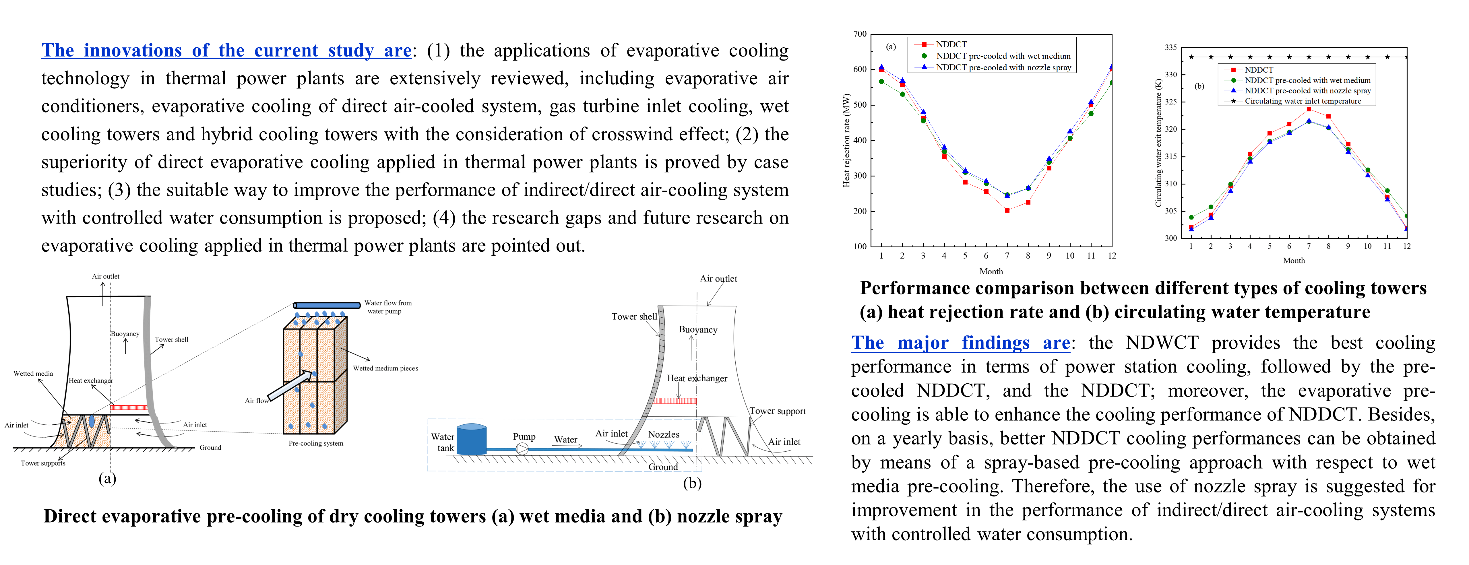
A review is conducted about the application of the evaporative cooling technology in thermal power plants. Different case studies are considered, namely, evaporative air conditioners, evaporative cooling in direct air-cooled systems, gas turbine inlet cooling, wet cooling towers, and hybrid cooling towers with a crosswind effect. Some effort is provided to describe the advantages related to direct evaporative cooling when it is applied in thermal power plants and illustrate the research gaps, which have not been filled yet. In particular, typical case studies are intentionally used to compare the cooling performances when direct evaporative cooling is implemented in different types of cooling towers, including the natural draft wet cooling tower (NDWCT) and the pre-cooled natural draft dry cooling tower (NDDCT). It is shown that the NDWCT provides the best cooling performance in terms of power station cooling, followed by the pre-cooled NDDCT, and the NDDCT; moreover, the evaporative pre-cooling is able to enhance the cooling performance of NDDCT. Besides, on a yearly basis, better NDDCT cooling performances can be obtained by means of a spray-based pre-cooling approach with respect to wet media pre-cooling. Therefore, the use of nozzle spray is suggested for improvement in the performance of indirect/direct air-cooling systems with controlled water consumption.Graphic Abstract
Keywords
Nomenclature
| a.b.c | Constant |
| A | Heat exchanger area, m2 |
| CCT | Conventional cooling tower |
| CD | Friction factor inside the tube |
| Cpa | Specific heat capacity of air, J/(kg⋅K) |
| Cpw | Specific heat capacity of water, J/(kg⋅K) |
| d | Diameter, m |
| DPEC | Dew-point evaporative cooling |
| Ds | Nozzle spacing, m |
| ef | The effectiveness of heat exchanger |
| FT | LMTD correction factor |
| H | Height, m |
| HVAC | Heating, ventilation and air conditioning |
| HWCCT | High-level water collecting cooling tower |
| ha | Heat transfer coefficient of air-side, W/(m2⋅K) |
| k | Thermal conductivity, W/(m⋅K) |
| K | Loss coefficient |
| l | Thickness of wet media, m |
| L | Length, m |
| m | Mass flow rate, kg/s |
| ma | Air mass flow rate, kg/s |
| mw | Hot water mass flow rate, kg/s |
| Nu | Nusselt number |
| Ny | Characteristic heat transfer parameter, m−1 |
| NDDCT | Natural draft dry cooling tower |
| NDWCT | Natural draft wet cooling tower |
| Pr | Prandtl number |
| Δp | Pressure drop, Pa |
| Δpa | Air-side pressure drop, Pa |
| Q1, Q2 | Heat transfer rate, W |
| qw | Water flow rate for the wet medium pre-cooling system |
| qav | Air-side mass flow rate, m3/s |
| Re | Reynolds number |
| Ry | Characteristic flow parameter, m−1 |
| ΔT1n | Logarithmic mean temperature difference, K |
| Tai | Air inlet temperature, K |
| Tao | Air outlet temperature, K |
| Ta3 | Air temperature before heat exchanger, K |
| Ta4 | Air temperature at the exit of heat exchanger, K |
| Twi | Hot water inlet temperature, K |
| Two | Hot water exit temperature, K |
| U | Overall heat transfer coefficient, W/(m2⋅K) |
| u | Speed, m/s |
| WCD | Water collecting device |
| Greek symbols | |
| ρa | Air density, kg/m3 |
| ρavi | Inlet air density, kg/m3 |
| ρavo | Outlet air density, kg/m3 |
| η | Cooling efficiency |
| ε | Surface roughness, m |
| μ | Dynamic viscosity, kg/(m⋅s) |
| σc | Contraction coefficient |
| θ | Half of apex angle of A-frame |
| θm | Mean flow incidence angle |
| Subscript | |
| 1 | The elevation of the ground level |
| 3 | The elevation of the heat exchanger entrance |
| 4 | The elevation of the heat exchanger exit |
| 5 | The elevation of tower exit |
| 6 | The ambient elevation at the same height as tower |
| a | Air |
| ct | Tower shell lower edge |
| ctc | Heat exchanger contraction loss |
| cte | Heat exchanger expansion loss |
| cw | Crosswind |
| e | Effective |
| fr | Front |
| he | Heat exchanger |
| ts | Tower supports |
| to | Outlet of the tower |
Evaporative cooling technology consists of evaporating water to adsorb heat from the air. One type of evaporative cooling is direct evaporation in which water is the direct contact with the air, and thus, both heat and mass transfer occur between the two fluids. The evaporative cooling process can be considered as a cooling and humidification process, whose cooling limit is the wet bulb temperature of ambient air. Theoretically, the evaporative cooling process is an approximately isenthalpic process, and the wet bulb temperature is constant during the process (Fig. 1) [1]. The air can be cooled by nozzle spray or wet media with circulating water, as long as it is unsaturated.
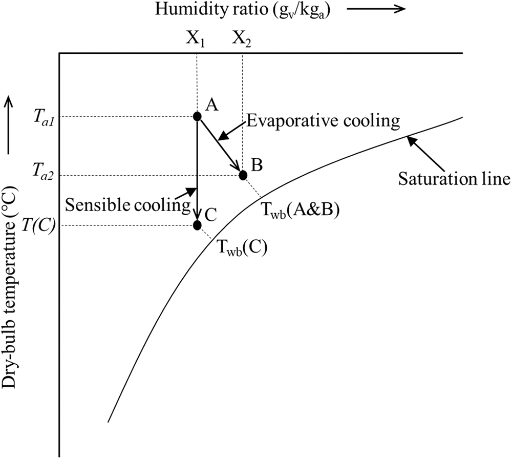
Figure 1: The process of direct evaporative cooling [1]
Direct evaporative cooling technology has been widely used in the world, mainly in power plants (such as cooling towers), improvement of building environment (such as evaporative cooling air-conditioning systems), textile ventilation systems, subway ventilation systems and farming and animal husbandry (such as greenhouse cooling) [2–8]. As one of the oldest cooling methods, direct evaporative cooling has been paid more and more attention by researchers because of its characteristics of energy conservation, environmental protection and economy [9–11]. Direct evaporative cooling has a large scope of applications in power engineering, such as evaporative air conditioning, evaporative condensers, gas turbine inlet cooling, and cooling towers [12].
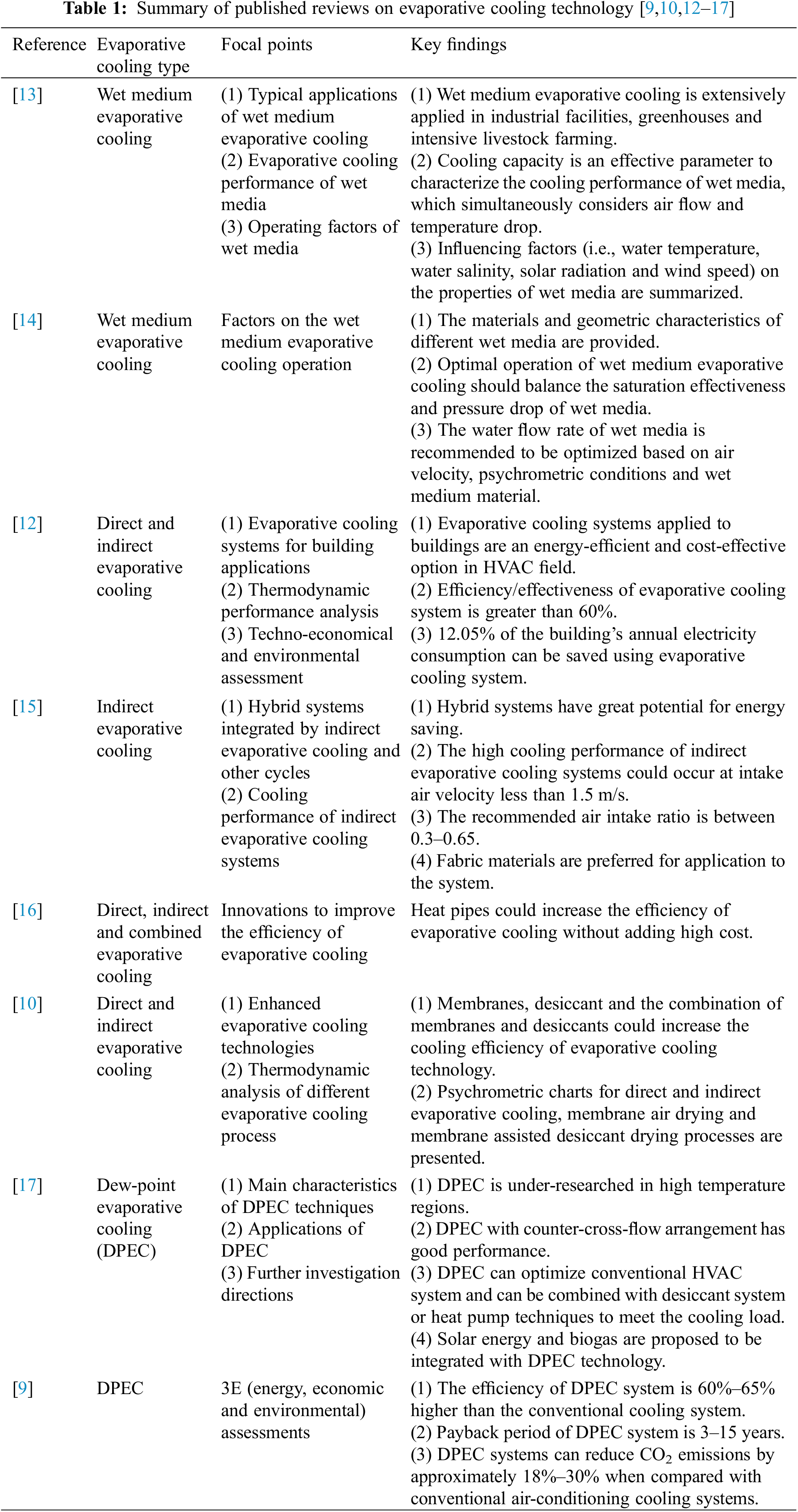
Various reviews related to evaporative cooling technology have been published in the last three years (Table 1). They focus on its application in buildings, its combination with other cycles, performance enhancement and evaluation of energy, economic and environmental effects. This paper focuses on the application of evaporative cooling technology in thermal power plants. The studies of performance enhancement of NDDCT by nozzle spray and wet medium evaporative pre-cooling are emphasized.
In this review, the principle of evaporative cooling technology is briefly introduced, and then researches on the applications of direct evaporative cooling technology in thermal power plants, especially in gas turbine and cooling tower are emphasized. The effects of fill arrangement and ambient crosswind on the performance of wet cooling towers are summarized, and the studies about high-level water collecting cooling towers are also presented. Special attention is paid to the researches on evaporative pre-cooling of NDDCTs, including nozzle spray pre-cooling and wet medium pre-cooling. A comprehensive study of evaporative cooling technology applied in wet cooling towers and in the pre-cooled NDDCTs is carried out to prove the superiority of evaporative cooling. Finally, some major conclusions and future work are proposed.
The novelties of the review are: (1) the applications of evaporative cooling technology in thermal power plants are extensively reviewed, including evaporative air conditioners, evaporative cooling of direct air-cooled system, gas turbine inlet cooling, wet cooling towers and hybrid cooling towers with the consideration of crosswind effect; (2) the superiority of direct evaporative cooling applied in thermal power plants is proved by case studies; (3) the suitable way to improve the performance of indirect/direct air-cooling system with controlled water consumption is proposed; (4) the research gaps and future research on evaporative cooling applied in thermal power plants are pointed out.
2 Application of Direct Evaporative Cooling in Power Plants
In an evaporative cooling system, water acts as the cooling medium. Evaporative cooling technology uses renewable energy (i.e., dry air energy) to achieve cooling effect. It is a cost-effective technology when compared with traditional mechanical refrigeration air conditioning systems. Usually, an evaporative cooling system can save 1/2 of the initial cost, 2/3 of the maintenance cost and 3/4 of the operating cost when compared with a traditional mechanical refrigeration air conditioning system [18]. Direct evaporative cooling technology has been widely used in power plants, including evaporative air conditioning, evaporative condensers, gas turbine inlet cooling and cooling towers. As an important infrastructure, the cooling tower affects significantly the safe and constant running of a power plant.
2.1 Evaporative Air Conditioning in Control Room
Evaporative air conditioning system can be split into direct evaporative air conditioning system, indirect evaporative air conditioning system, indirect-direct combined air conditioning system, evaporative cooling-mechanical refrigeration combined system [19,20]. The characteristics of evaporative air conditioning are: circulating water as the refrigerant, no fluorine and chlorine compounds, no leaks and disposal issues after scrapping of above compounds, no pollution to the environment, simple system, less energy-consuming components, well economic advantages in operation and initial investment, but its application is greatly affected by the environment.
For power plants, evaporative air conditioning has tremendous advantages for the large difference between dry and wet bulb temperature of air in hot-dry regions. A large amount of sensible heat is emitted from the auxiliary equipment in steam turbines and frequency conversion machine rooms. Therefore, the combination of direct evaporative cooling and mechanical ventilation is very suitable for dealing with high sensible heat and can greatly reduce sectional area of the wind pipe. Evaporative air conditioning unit for frequency conversion machine rooms of power plants is shown in Fig. 2.
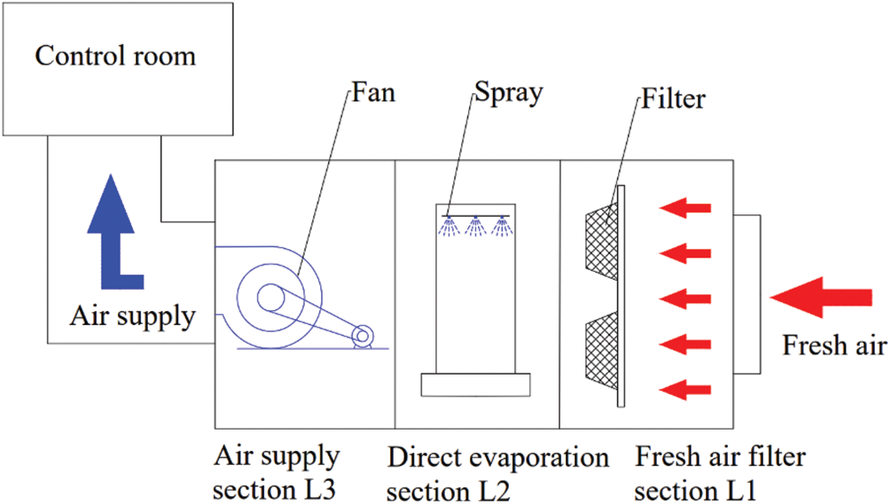
Figure 2: The process of direct evaporative cooling for air conditioning of a control room
Tang et al. [21] pointed out that it was necessary to seriously consider the effects of heating, ventilation and air conditioning (HVAC) systems on the thermal power plants during the design period. They mentioned that evaporative cooling ventilation system can reduce the air temperature by 10°C. He et al. [22] also suggested that the designers should keep trying to use an evaporative air handling unit in air-cooled inverter room. This technology could not only keep the good quality of air, but also avoid outdoor dust entering the indoor with the ventilation system, so that the indoor environment could be improved. He et al. [22] compared different types of air conditioning systems in the air-cooled inverter room of power plants. The economic efficiency of electric power refrigerating air conditioners and evaporative air conditioners were compared by case study. The results showed that the initial investment and operating costs of evaporative air conditioners were lower than conventional air conditioners. Xu [23] studied the application of evaporative air conditioners in hydropower plants. The results showed that evaporative air conditioners were feasible and economical in hydropower plants. Li et al. [24] explored the application of two-stage direct evaporative air-conditioning units for nuclear power plant. The results of the experiment indicated that the system could make the dry bulb temperature of indoor air close to the wet bulb temperature of outdoor air in the middle humidity regions when the temperature difference is 4°C to 5°C between the dry and wet bulb temperature of outdoor air. It was indicated that the two-stage direct evaporative air-conditioning unit has a bright prospect in the nuclear power plant.
In the process of thermal power generation, exhaust steam cooling is an important part of the power generation process. Cooling water is usually used as the medium to cool the exhaust steam. In dry and hot areas, air-cooled units are gradually developed due to the water scarcity. The cooling effect of exhaust steam cooling is greatly affected by the environmental factors since air is used as the cooling medium. Especially in hot periods, the rated output of 600 MW air-cooled unit will be reduced by 10%∼20% [25]. The research showed that evaporative condenser can improve the cooling effect of air-cooled units by combining evaporative cooling technology with air-cooled units (Fig. 3). As shown in Fig. 3, the spray cooling system will open when the ambient air heats up while it is shut down when the direct air-cooling system meets the cooling load to save water. The cooling mechanism of evaporative cooling assisted direct air-cooled system includes sensible cooling and latent cooling by water evaporation.
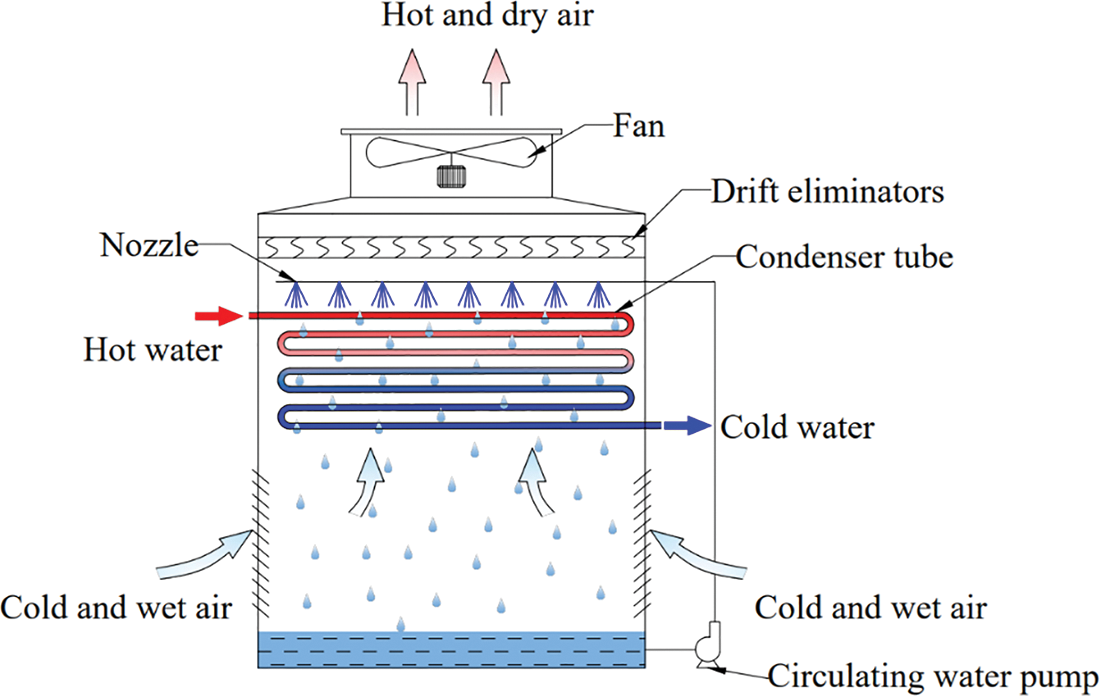
Figure 3: Evaporative cooling assisted direct air-cooled system
Du et al. [26] established a theoretical analysis model of the evaporative condenser. The case analysis indicated that the evaporative condenser could apparently decrease the steam turbine’s exhaust pressure, which helped to improve the steam turbine’s functional capacity. Wei et al. [27] systematically analyzed the feasibility of application, which evaporative condenser was used for steam condensation of small steam turbine with steam feed pump. The results showed that the advantages of evaporative condenser were energy saving, water reserving, low operation and maintenance costs than the conventional water-cooled unit. Guo et al. [28] explored the feasibility of the application of evaporative condensers for thermal power plant cooling systems, and proved the feasibility by application cases. Bustamante et al. [29] studied the performance of air-cooled condensers under different operating conditions. They found that the water-cooled power plants can be replaced by air-cooled condensers, which has the advantages of increasing air flow, reducing air side thermal resistance and air side pressure loss.
For the numerical simulation of spray cooling of direct air-cooled units, Wang et al. [30,31] conducted a series of studies on the application of spraying cooling for the performance improvement of the direct air-cooled unit. Through numerical simulation, it was found that the spray cooling system could significantly reduce the inlet air temperature and improve the unit’s summer output. Simultaneously, the system showed that the economic benefits were considerable by the economic analysis. Zhang [32] carried out numerical simulation on the air-cooled unit by spray cooling system as well as found that the spray cooling could improve the air condenser’s heat exchange. He found the air-water surface and the residence time of droplets in the heat transfer zone were important factors affecting the heat and mass transfer between droplets and air. Zhou et al. [33] carried out numerical simulation about spray humidification system of the air-cooled unit. The results showed that the optimal nozzles arrangement could increase the unit vacuum by 7%, and the coal consumption for power generation had been reduced by 7 g/(kW⋅h). Hui [34] modified the fan model in the direct air-cooled unit by the spray humidification system, as well as used the MRF model to simulate the fan. Simultaneously, the cooling effect of the spray humidification system under the rotating flow field was simulated.
2.3 Inlet Air Cooling of Gas Turbines
The gas turbine’s performance is greatly influenced by the ambient temperature especially in summer, which is very likely to cause an imbalance in the supply and demand of power generation [35]. The inlet air cooling can maintain high efficiency power generation of the gas turbine [36]. At the present, the commonly used inlet air cooling methods are: direct evaporative cooling method and electric refrigeration. The electric refrigeration consumes a certain amount of external energy, but the temperature drop is large; the direct evaporative cooling method cools air through water evaporation. The cooling effect of direct evaporative cooling is greatly affected by the temperature and relative humidity of the ambient air [37]. In some areas as hot and dry, direct evaporative cooling method has certain economic advantages when compared with electric refrigeration.
Fig. 4 shows the evaporative cooling unit for inlet air cooling of gas turbine in power stations. Mohapatra et al. [38] compared the inlet air cooling of gas turbine by evaporative cooling and by vapor compression cooling. It was found that vapor compression cooling could increase the work and efficiency of the power plant by 18.4% and 4.18%, respectively under high ambient temperature and high relative humidity, which was better than evaporative cooling. However, when the ambient relative humidity and ambient temperature were low, evaporative cooling was better than vapor compression cooling. Najjar [39] explored the gas turbine engine with inlet air precooler, the power, efficiency and fuel consumption of the engine were compared with the ordinary gas turbine engine (i.e., without pre-cooling). It was found that the power, efficiency and fuel consumption of the gas turbine with inlet air pre-cooling could be increased by 21%, 38% and 28%, respectively. Najjar et al. [40] investigated the inlet air cooling of gas turbines by combined cooling systems. It was found that the gas turbine’s power and efficiency could be increased by 15% and 9% using the indirect evaporative cooling system with absorption chiller, while indirect evaporative cooling system with mechanical chillers could increase the power and efficiency by about 7.81% and 2.24%, respectively. Shukla et al. [41–43] indicated that a cooling system consisting of inlet air cooling, steam injection, and film cooling is the best combination for gas turbine cycle to perform high thermal performance. Then they conducted a thermal performance evaluation of gas turbine integrating inlet cooling, injection steam cooling, and film cooling. They found that the thermal efficiency of the gas turbine cycle is at its peak at turbine inlet temperature of 1800 K and pressure ratio of 24. The thermal efficiency of gas turbine with the hybrid cooling system is increased by 18.63% under the same conditions when compared to a simple gas turbine cycle. Subsequently, they further investigated the effect of operating conditions on the thermal performance of a gas turbine combined cycle power plant. The output specific work and thermal efficiency of the combined cycle power plant are increased by 17.34% and 6.78%, respectively when the ratio of steam to air increases from 3% to 7% at a cycle pressure ratio of 24. Barakat et al. [44] proposed a novel inlet air cooling system composed of an earth-air heat exchanger and a fogging cooling system for gas turbine and carried out a comparative study on the performance of a 125 MW gas turbine unit. The annual average power of the gas turbine with hybrid cooling system and fogging cooling is increased by 9.8% and 6.6%, respectively when compared to the gas turbine unit without cooling. In addition, the hybrid inlet air cooling system can save 50% of water consumption in hot days when compared to the fogging cooling system.
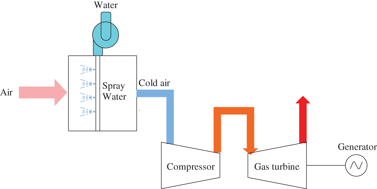
Figure 4: Evaporative cooling unit for inlet air cooling of gas turbines at power plants
The main applications of direct evaporative cooling in cooling towers are wet cooling towers and hybrid cooling towers in the power plants. The turbine exhaust steam is condensed into liquid water in the condenser. The circulating cooling water is used to cool exhaust steam in many power plants. Cooling towers are generally utilized to decrease the circulating water temperature.
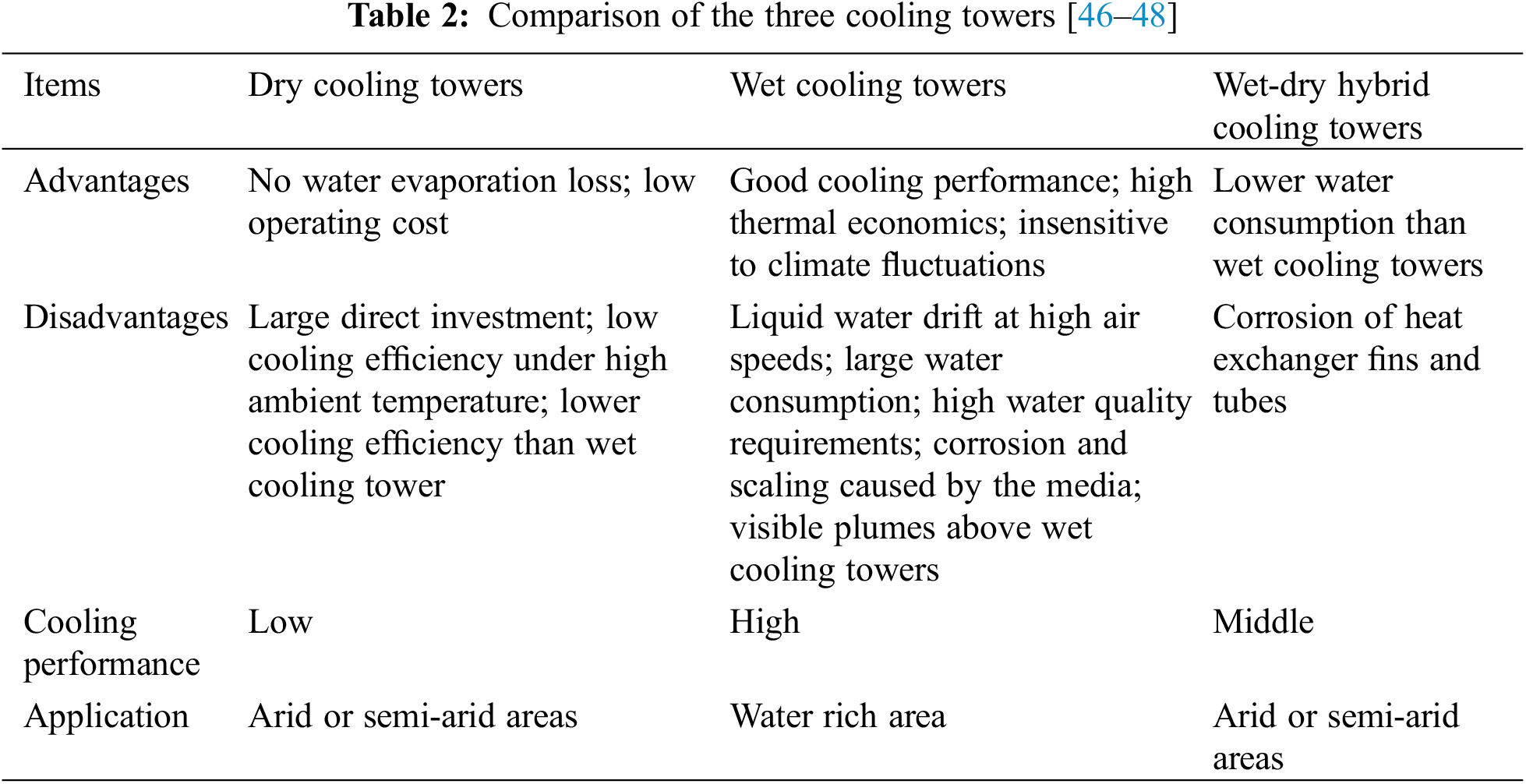
The cooling tower is divided into three types (i.e., wet cooling tower, dry cooling tower and wet-dry hybrid cooling tower) [45]. The circulating water is cooled by direct evaporation in wet cooling tower. The dry cooling tower applied the heat exchanger to cool the circulating water. Wet-dry hybrid cooling tower is a combination of wet cooling and dry cooling [46,47]. These cooling towers are compared in Table 2. The research of the application on evaporative cooling in power plant cooling towers is discussed in detail below.
3 Application of Direct Evaporative Cooling in Wet Cooling Towers
Fig. 5 shows a NDWCT, the air contact directly with the circulating water and carries out mass and heat transfer in the rain zone; The circulating water is cooled by three zones, i.e., the rain zone, water distribution zone and the wet medium zone. The function of buoyancy is to drive the air in the NDWCT [49]. The temperature difference between inside hot air of the tower and ambient cool air generated density difference of air, which produced the buoyancy. In Fig. 5, the drift eliminators collect drifting water droplets, the distribution system makes the water distribution more uniform.
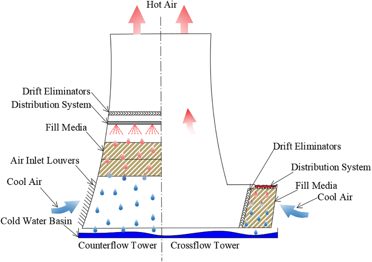
Figure 5: A typical NDWCT
NDWCTs have been applied diffusely in thermal and nuclear power plants. The major factors affecting the cooling performance are cooling tower structure, wet media, circulating water flow rate and temperature, and environmental meteorological conditions [50–54].
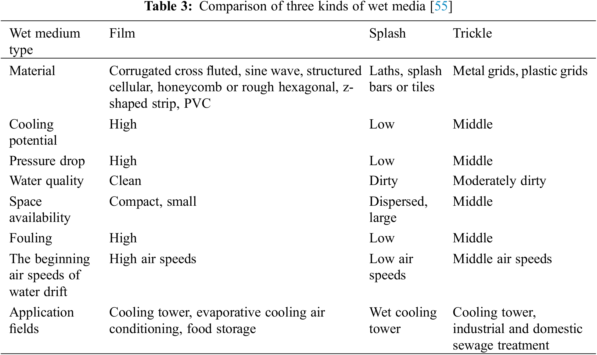
Wet media play a vital role in the wet cooling tower, which occupies the highest proportion of heat transfer in the tower [46]. As shown in Fig. 6, wet media are mainly divided into splash fills, film fills and trickle fills [55]. Splash fills are mostly used in cross-flow towers, which are characterized by good anti-pollution characteristics. The disadvantage of splash fills is that the cooling efficiency per unit volume is much lower than that of film fills, difficult installation and high maintenance costs. Film fills can be mainly divided into two types: interlaced corrugated and vertical corrugated. They are designed to maximize heat transfer and mass transfer performance under the conditions of minimum resistance. Trickle fills are a combination of splash and film fills. Different materials have been used to make fills, including wood, asbestos, cement, cement mesh, plastic, fiberglass, ceramics and metals [56–59]. The service life of wet media is related to material, water quality and other factors. Bending, fiber decay and decomposition of organic materials limit the service life of fiber wet media. Generally, the service life of fiber media (i.e., aspen fibers, eucalyptus fibers, jute fibers, etc.) is lower than the service life of rigid media (i.e., cellulose, PVC, glass fiber, etc.) [13,14]. However, different materials have different service life among the two materials, for example, the life span of jute fiber is shorter than the life span of aspen fiber and palm fiber. The service life of wet media is also affected by water quality. If water is too dirty, it will cause scale build-up and algae growth, which is the main cause of wet media degradation [55]. The price of wet media is also mainly related to the material, the cost of fiber wet media grown in nature is lower than the price of rigid media with reprocessing, such as the cost of glass fiber is higher than natural fibers. Different types of wet media are compared in Table 3.
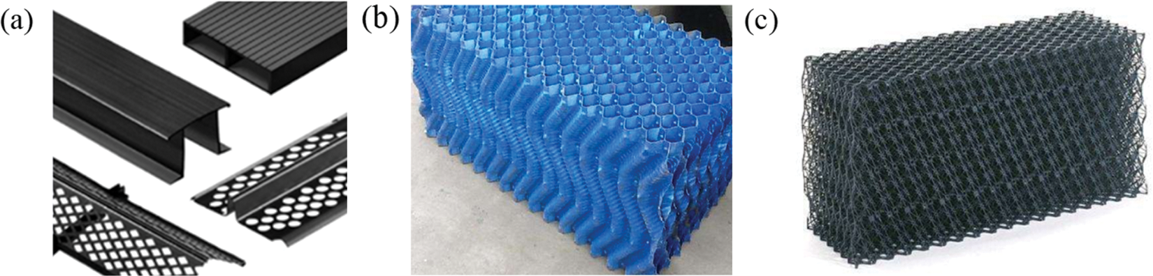
Figure 6: Direct evaporative cooling tower fills: (a) splash, (b) film and (c) trickle [55]
Fills have always been a research highlight. Zhang et al. [60] used numerical simulation to study the optimization of non-uniform fills coupled with water distribution in wet cooling towers. It was found that the outlet water temperature could be decreased by 0.31°C and the evaporation loss could be reduced by about 3.3% with the optimization of non-uniform fills and water distribution. Zhou et al. [61] experimentally compared the resistance characteristics and thermal performance of five different patterns of non-uniform fills in wet cooling towers. They found the best fill pattern among the studied patterns with the highest ventilation rate (151.6 m3/h) and the lowest resistance coefficient (32.6). Lyu et al. [62] numerically studied the effects of fill layout patterns on the cooling performance of wet cooling towers. The results showed that the air flow field was more stable and uniform when compared with the traditional uniform fill layout. Singh et al. [63] experimentally studied the performance of wet cooling tower using three types of fills (i.e., wire-mesh, honey-comb and wooden splash fills). It was found that the wire-mesh fill was the most favorable fill to improve the performance of the cooling tower. Gao et al. [64] explored the tower’s thermal performance using non-uniform S-corrugated fills in the wet cooling tower and found that the thermal performance can be increased by 30% under non-uniform arrangement compared with uniform arrangement. Zhou et al. [65] used experimental and numerical methods to analyze the thermal performance of wet cooling tower. They found that the cooling water outlet temperatures of the wet cooling tower with fills are within 0.6°C∼1.5°C, which is lower than that of wet cooling tower without fills.
In addition, researches about the optimization of water distribution have been carried out. Zhang [66] explored the effects of fill height, internal and external zone of water drenching density on the cooling performance of the counter-flow NDWCT by a 2D model. The temperature of exit water is decreased by 0.42 K due to the fact that the external zone of water drenching density decreases from 1.75 to 1.50 kg/(m2⋅s). In addition, the outlet water temperature is decreased by 0.32 K due to the action that the fill height of internal zone improves from 2.0 to 2.2 m. Li et al. [67] developed a three-dimensional model to analyze the effect of non-uniform water distribution on the cooling performance of a wet cooling tower. They found that the cooling performance of the cooling tower was the best when the water flowrates at the inner, middle and outer zones of the tower were 400, 2600 and 6000 kg/s, respectively. Zhao et al. [68] established a two-dimensional NDWCT model. On the one hand, the water distribution was optimized to make the water flow of the outer region of the tower larger than that of the central region; on the other hand, the fill arrangement was optimized by reducing the fill height in the tower central region. The results demonstrated that the temperature of exit water of the tower could be reduced by 0.52 K through optimizing the water distribution and fills at the same time.
The thermal performance of wet cooling tower is greatly affected by the crosswind. Zou et al. [69] experimentally tested a high-level water collecting wet cooling tower (HWCCT) with 1000 MW power unit under crosswind, they studied the ventilation performance and the inlet air flow field of the tower. The results showed that inflow air uniformity in the circumferential direction was destroyed by the crosswind, the wind speed of lateral and leeward sides was decreased and the wind speed of windward side was increased. Al-Waked et al. [70] studied the performance of NDWCTs under crosswind by a 3D numerical model and found that the change of outlet water temperature (ΔTwo = Two − Two(ucw = 0 m/s)) increases when the crosswind speed (ucw < 8 m/s) increases. However, the change of outlet water temperature decreases when crosswind speed increases at high speed of crosswind (ucw > 8 m/s) (Fig. 7).
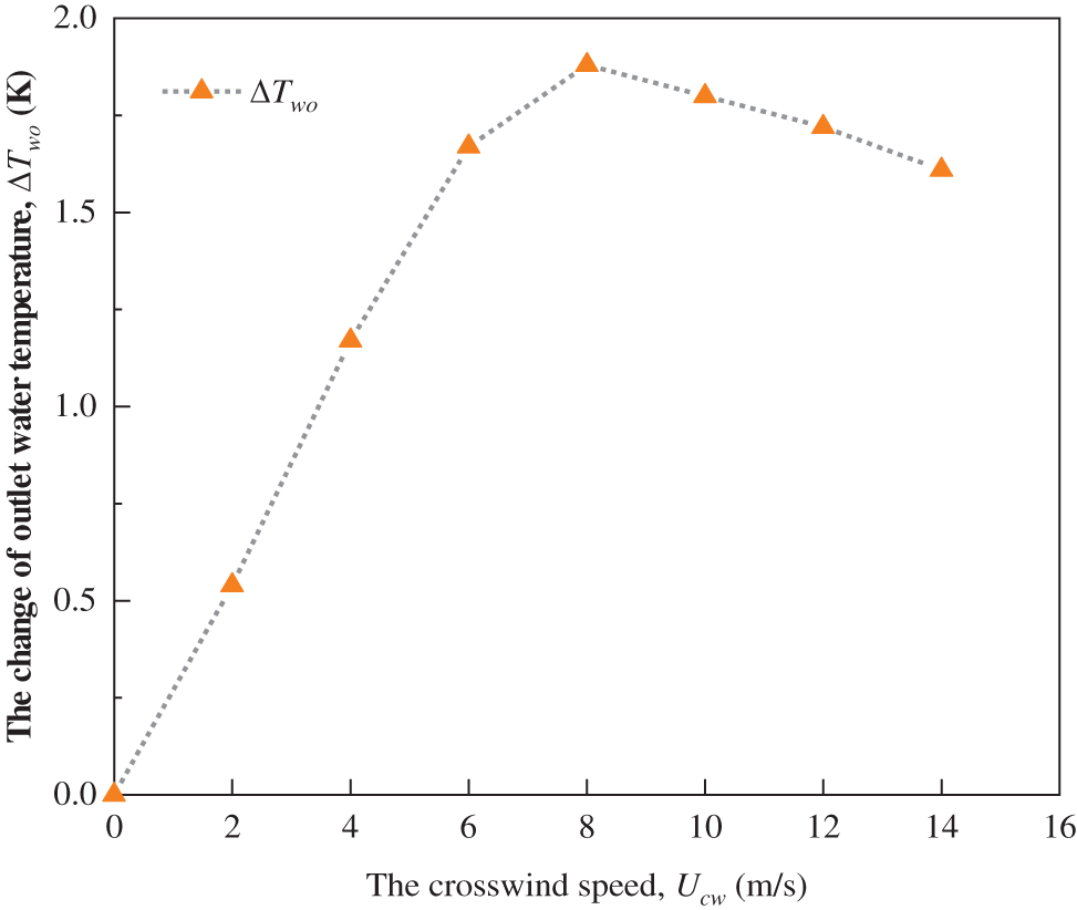
Figure 7: Changes of ΔTwo with the increase in crosswind speed [70]
Al-Waked et al. [71] found that the NDWCT’s performance could be improved at high crosswind speeds. The exit water temperature improved by 1.7 K with 7.5 m/s of the crosswind speed. Gao et al. [72] experimentally studied the thermal performance of counter-flow NDWCT with crosswind. The study showed the temperature difference (ΔT = Twi − Two) of circulating-water and cooling coefficient of efficiency (η) are impacted by the crosswind, and ΔT and η reduce mostly by 6.0% and 5.0%, respectively. Research by Chen et al. [73] showed that the crosswind caused uneven airflow distribution in the wet cooling tower and found that the total ventilation rate increased first and then declined when crosswind speed in the tower increases. The introduction of air flow direction channels could reduce the impact of crosswinds. Gao et al. [74] discovered that the distribution of the pressure and air speed near the inlet and outlet of NDWCT could be changed by the crosswind, the uniformity of flow field in NDWCT would be destroyed under crosswind. The low-pressure and air vortices areas would form inside the cooling tower as the crosswind speed increases.
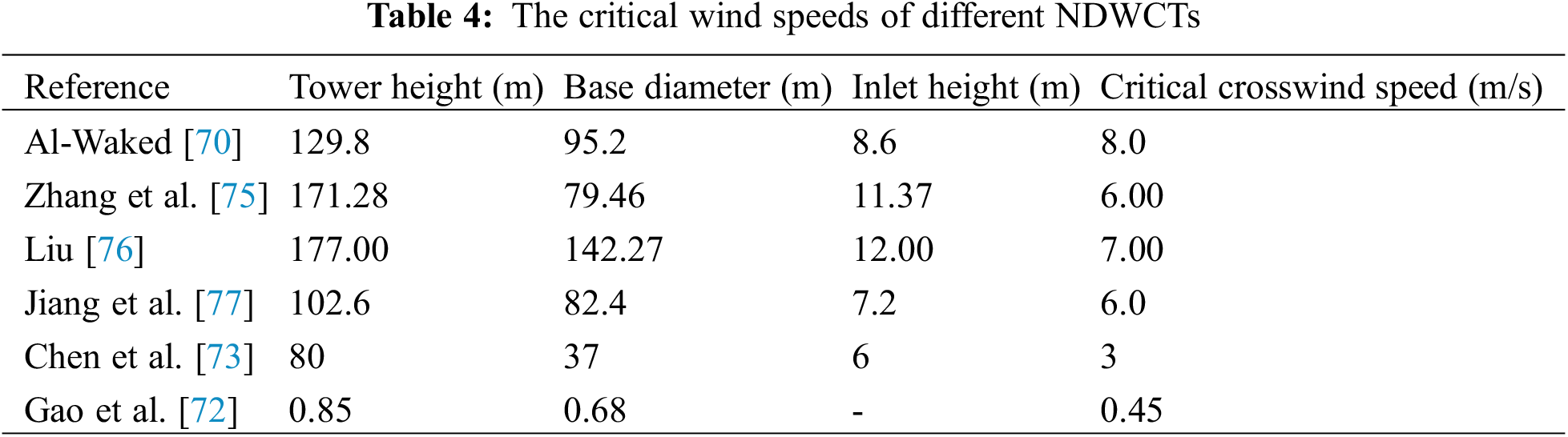
Through the above analysis, the cooling performance of the NDWCT first decreases and then increases when the crosswind speed increases, and the lowest cooling performance of NDWCTs occurs due to the critical crosswind speed. Table 4 shows the critical wind speeds for different NDWCTs.
In response to the adverse effects of crosswinds, scholars have proposed a variety of wind protection measures. Zhang et al. [75] clarified the influence of crosswind on the ventilation and thermal performance of super-large NDWCTs. It was found the crosswind destroyed the symmetry of the aerodynamic field of the cooling tower. The vortex generated by crosswind leads to the increase of air flow resistance and the decrease of heat and mass transfer between air and water. For reducing the adverse effect of crosswind on a NDWCT, Chen et al. [78] carried out a simulation study on the NDWCT with air ducts in the rain zone and air deflectors around the tower inlet. The simulation discovered that the average water temperature at the surface of the water basin was reduced by 1.27°C with a crosswind velocity of 3.6 m/s. Kashani et al. [79] explored the thermal efficiency of the NDWCT under crosswind by installing the air-deflectors along the circumferential direction of the air inlet of the tower. They found that the thermal efficiency of the tower can be increased by 8.6% when the wind speed is greater than 2 m/s. Al-Waked et al. [80] discussed the influence of windbreak walls on the NDWCT’s thermal performance under crosswind conditions. The results demonstrated that the cooling water temperature was reduced by 0.5∼1 K at all the studied crosswind speeds by installing windbreak walls in the rain area. Chen et al. [81] optimized the structural parameters of the cross walls through a hot model test. They revealed that the cross walls could improve the tower’s thermal performance. They proposed that the solid wall at θ = 0° results in good thermal performance at low crosswind speed while the porous wall has good thermal performance at high crosswind speed. Chen et al. [82] installed air ducts in a NDWCT to solve the poor heat and mass transfer in the internal zone of the tower. It was found that the tower’s performance improvement due to the air ducts becomes more pronounced with the increase in crosswind speed.
3.1.3 Feasibility Analysis of Evaporative Pre-Cooling of Wet Cooling Towers
The heat and mass transfer zone in a NDWCT (as shown in Fig. 5) consists of water distribution zone, wet medium zone and rain zone. High-temperature water is sprayed out by nozzles in the water distribution system, and flows through the wet medium zone and rain zone in turn, and finally falls into the water basin. Meanwhile, the ambient air is driven in the tower by buoyancy force, and transfers heat and mass with the high temperature water. Generally, the heat transfer in the water distribution zone, wet medium zone and rain zone accounts for around 10%, 70% and 20% of the total heat transfer in a wet cooling tower, respectively [53]. The heat transfer process in a NDWCT can be divided into latent heat transfer and sensible heat transfer, where latent heat transfer plays a dominant role in the whole heat transfer process, accounting for more than 80% of the total heat transfer in the tower [53]. If the evaporative pre-cooling system is applied to the NDWCT, the state change of air is shown in Fig. 8. The heat transfer process of air in the evaporative pre-cooling system (i.e., the process A → B in Fig. 8) is approximately an iso-enthalpy process, where the temperature of the air decreases and the humidity of the air increases. The pre-cooled air then exchanges heat with high temperature water inside the wet cooling tower (i.e., the process B → C in Fig. 8), which is a warming and humidification process. With the help of evaporative pre-cooling, the temperature of the inlet air is reduced and the sensible heat transfer inside the NDWCT is improved. However, evaporative pre-cooling humidifies the inlet air and then impairs the mass transfer inside the NDWCT. As a result, evaporative pre-cooling does not work well in the pre-cooling of a NDWCT. Therefore, evaporative pre-cooling system is not recommended for pre-cooled NDWCTs.
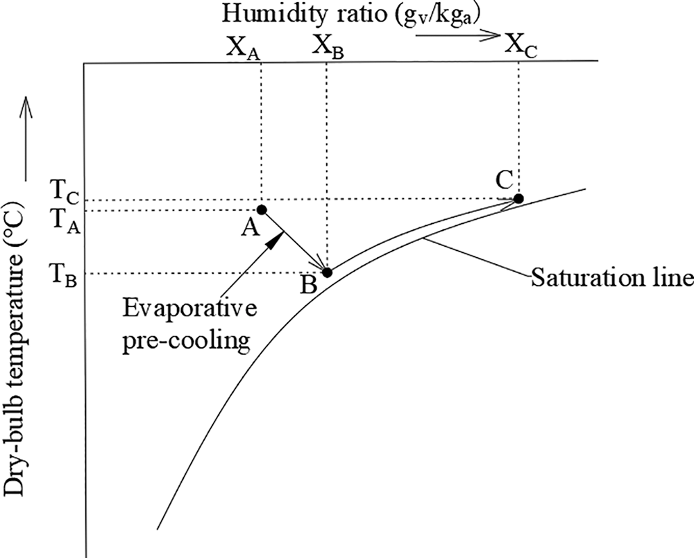
Figure 8: Psychrometric chart of evaporative pre-cooling of wet cooling towers
3.2 High-Level Water Collecting Cooling Towers
NDWCT can be classified into conventional cooling tower (CCT) and HWCCT. Fig. 9 shows a typical HWCCT. The water collecting devices (WCDs) replaced the rain zone in HWCCT. The free-falling height of water droplets in CCT is high (i.e., rain zone), and the potential energy of the cooling water is lost. Meanwhile, the head of water supply pump is large and the energy consumption is high. However, in the HWCCT, the cooling water flows through the fills and is collected by the WCDs [83]. Hence, the water potential energy is saved by the WCD in the rain zone. HWCCTs are promising compared with the CCTs because their merits are saving water potential energy in the rain zone, low noise and decreased pump head [84].
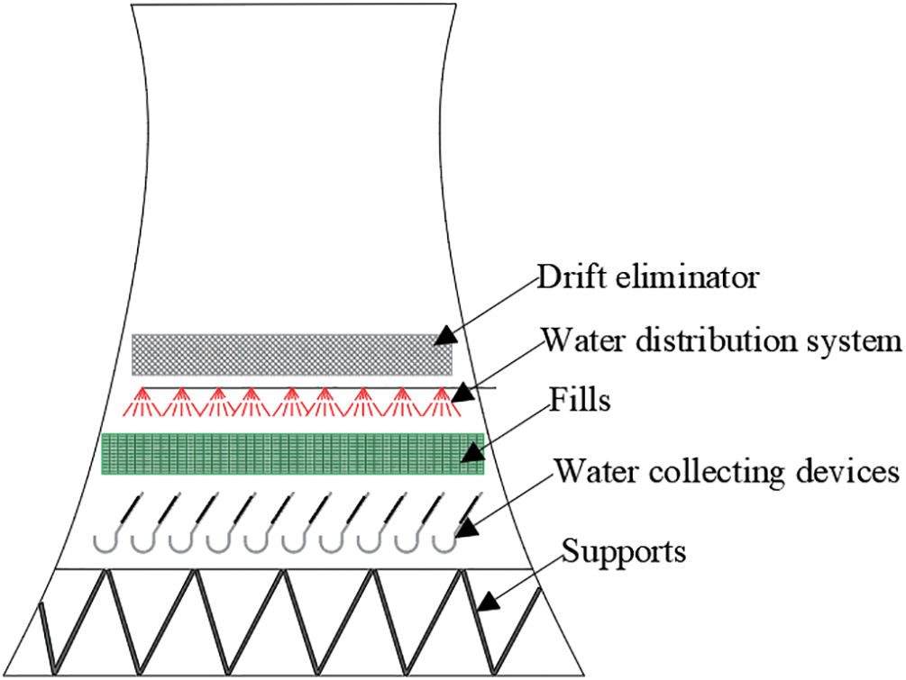
Figure 9: A typical HWCCT [85]
In 1980s, the HWCCTs occurred firstly at a French nuclear power plant [86,87]. At the present, there are few studies on HWCCT. Jin et al. [88] discussed a 330 MW HWCCT could save 7822.9 MW⋅h power a year when compared to a conventional tower. Li [89] conducted an energy-saving analysis of a HWCCT. It was found that the energy-saving and noise-reducing effects of the HWCCT was remarkable, and it had broad application prospects for super-large cooling towers. Li et al. [90] found that HWCCT is recommended in long-term operation due to its cost efficiency analyzing the economics of HWCCT and CCT. Zou et al. [69,91] studied the HWCCT’s ventilation and thermal performance under crosswind through field tests. It was found that the HWCCT’s thermal performance under low-crosswind speed was better than that under high-crosswind speed. Moreover, Dang et al. [92] studied the effect of crosswind on the cooling performance of fill zone, rain zone and spray zone in a HWCCT. It was found that the fill zone was the main zone for heat and mass transfer, and the fill zone was affected by crosswind sensitively under low circulating water flow rate and small crosswind speed. To reduce the adverse impact of crosswind, Chen et al. [93] developed a 3D model of HWCCT with cross walls. It was found that the influence of crosswind on the cooling performance of the HWCCT could be reduced when the porosity of the cross wall was 0.33∼0.53. In addition, Chen et al. [94] proposed different water collection methods at the periphery and center of the tower, which could eliminate vortex and improve the heat dissipation capacity at the periphery of the tower.
The HWCCT with the WCDs is different from traditional wet cooling towers, they have impact on the HWCCT’s performance through the flow resistance on the air-side, thus interfering with the airflow. Therefore, WCDs are important for efficient operation of HWCCT. Some researchers focused on WCDs. Wu [84] compared the aerodynamic field and temperature field of HWCCT and CCT by numerical simulation, and obtained the optimum installing height and the angle of WCDs. Lyu et al. [95] studied the airflow fields in WCDs by combining wind tunnel test with numerical simulation, which laid a foundation for the optimizing of the WCDs. The above researches on WCDs were carried out under dry condition, but the WCDs work under wet condition in the actual operation of HWCCT. Therefore, He et al. [85] studied the air-side flow resistance of U-type, V-type and rectangular WCDs under wet and dry conditions through wind tunnel tests. The results showed that the flow resistance and water collecting capacity of U-type WCDs were the best when compared with the other two types. Further, He et al. [96] experimentally investigated the airflow through U-type WCDs by a wind tunnel. They found that the average pressure drop is 86% at wet mode higher than that at dry mode when the air speed is 0.5∼3.0 m/s and the WCDs have lower pressure drop when the WCDs had larger slab spaces and larger slab angles.
4 Application of Direct Evaporative Cooling in Improving Performance of Air-Cooled Towers
A NDDCT relies on buoyancy to drive the airflow through the radiator inside the tower to exchange heat, it is a good cooling equipment due to the advantage of water saving when compared with the NDWCT. The air-cooled system in thermal power plants can be classified as indirect and direct air-cooled system. Indirect air-cooled system means the exhaust steam is cooled by cooling towers indirectly. That is to say, circulating cooling water cools the steam turbine exhaust in the condenser, and dry cooling towers cool the circulating cooling water. Direct air-cooled system means that the steam discharged from the steam turbine is directly cooled by the dry cooling units, instead of the condensers [45]. The indirect cooling system can be divided into Hammon system (Fig. 10) and Heller system (Fig. 11) according to the difference in the condenser type and the radiator arrangement. The Heller system uses a jet condenser and the radiator arranged outside the air-cooled tower. The Hammon system uses a surface condenser, and the radiator is arranged inside the tower. Chen et al. [97] compared the advantages and disadvantages of surface indirect and direct air-cooled system, and found the indirect air-cooled system was recommended considering the economics. The Heller system has high requirements on water quality and complicated equipment since the cooling water is directly mixed with the exhaust steam. Therefore, the Harmon system become popular. The air-cooled tower discussed below is the NDDCTs in Harmon system unless otherwise stated (Fig. 10).
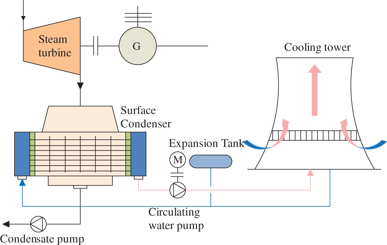
Figure 10: Hamon indirect cooling system
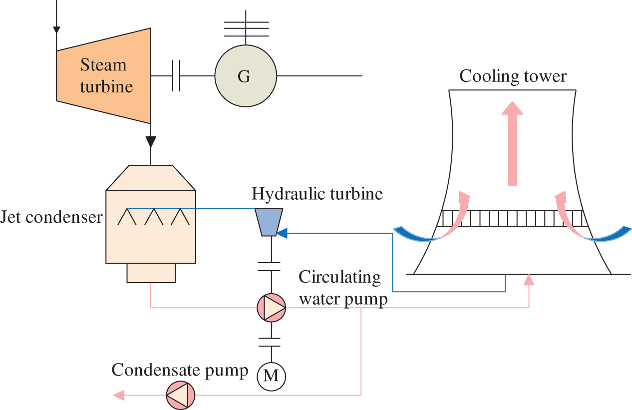
Figure 11: Heller indirect cooling system
In the air-cooled towers, the heat transfer consists only of convective heat transfer since the water indirectly contacts with the air. However, in the wet cooling tower, the cooling water directly contacts with the air and the heat transfer occurs by convective heat transfer and evaporation. In air-cooled cooling tower and wet cooling tower, the water can be cooled to dry bulb temperature and wet bulb temperature of the ambient air, respectively. The cooling water outlet temperature of wet cooling tower is lower when compared with air-cooled tower. Besides, the cooling performance of air-cooled towers is significantly decreased in the high-temperature environment [98]. It is vital to optimize the air-cooled tower to improve its cooling effect during the hot period [46,53].
According to the operation of NDDCT, increasing the heat rejection rate of NDDCT can be obtained by increasing the ventilation rate, increasing the heat transfer temperature difference and introducing evaporation, such as dry/wet hybrid cooling tower, inlet air pre-cooling technology. The following sections will review the hybrid cooling tower and inlet air pre-cooling technology.
The hybrid cooling system is a combination of wet cooling and dry cooling, which can be divided into two patterns, (i.e., separate pattern and joint pattern). The dry cooling part and the wet cooling part are built in the joint hybrid cooling system (Fig. 12), which leads to the small land occupation and complex structure of the system. For the separate hybrid cooling system (Fig. 13), the two parts are introduced into the cold end of the power plant separately, the advantage of this system is convenient in maintenance, but this system has large land occupation and large capital investment [99,100].
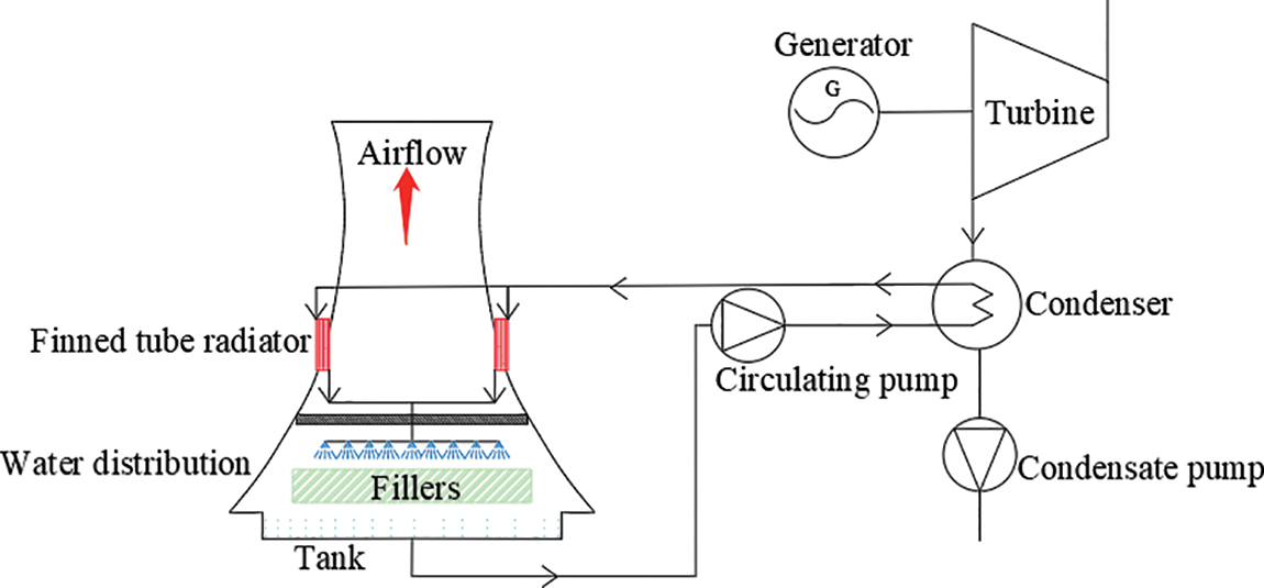
Figure 12: Joint hybrid cooling system
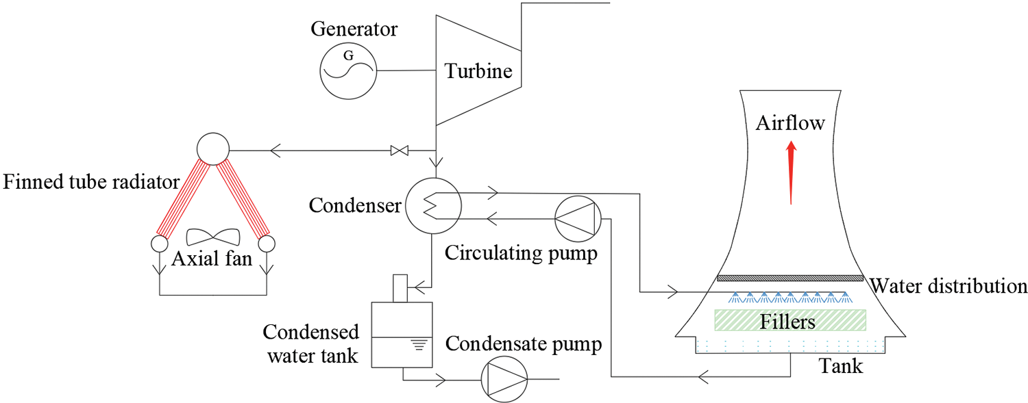
Figure 13: Separate hybrid cooling system [101]
The hybrid cooling tower is a compromise between the wet and the dry cooling. In Fig. 12, the dry section is the upper section in the hybrid cooling tower, the cooling water is cooled firstly by the finned tube radiator; the lower part is the wet section, the cooling water from the dry section is further cooled in the wet section through heat and mass transfer in the zones of water distribution, fill and rain zone.
Huang et al. [102] explored the cooling performance of a hybrid cooling tower by establishing a calculation model under variable operating conditions. The results indicated that the hybrid cooling tower provided high cooling performance at large spray flow ratio and low ambient humidity. Hu et al. [103] developed a new thermodynamic model to predict the water-saving performance of a hybrid cooling tower, they found the hybrid cooling tower could save 5.04 kg/s of water at the ambient temperature of −9.6°C, air flow rate of 465.12 kg/s, heat exchanger units of 26 and could save 0.61 kg/s of water at the ambient temperature of 14.7°C, air flow rate of 290.44 kg/s, heat exchanger units of 6. Hu et al. [101] studied the effect of environmental parameters on the cooling performance of a hybrid cooling system for a 660 MW thermal power plant by numerical simulation. The results showed that the cooling performance deterioration of the wet cooling system and hybrid cooling system are less severe than that of the dry cooling system. The cooling performance of the hybrid cooling system is superior to that of dry cooling system with 45.84% lower fan power consumption at the dry-bulb temperature of 0°C. Xia et al. [104] compared the evaporation loss of natural draft hybrid cooling tower and NDWCT for a 300 MW thermal power plant by simulation. The study found that natural draft hybrid cooling tower saves more than 95% of water when compared with NDWCT. The numerical calculation and experimental study of a hybrid cooling tower were constructed by Asvapoositkul et al. [47]. It was found that the wet cooling had better cooling performance, the wet cooling system was more sensitive to the change of water flow, and the air-cooled system was more sensitive to the change of air flow.
4.3 Pre-Cooling Inlet Air System
Increasing the heat transfer temperature difference is another effective way to improve the heat exchange rate of air-cooled tower, e.g., the air inlet pre-cooling. The inlet air of the tower is pre-cooled and the temperature difference between the air and hot water inside the heat exchanger is enlarged, so the cooling performance of the tower is increased. Evaporative pre-cooling can be introduced by two methods (i.e., wet media and nozzle spray) [1].
Fig. 14 shows a NDDCT pre-cooled by wet media [105]. The wet media are installed in the air inlet area of NDDCT, and the water is distributed by the distributor above the wet media to uniformly wet the media. The water deposited on the wet media evaporates and the cooled air absorbs heat from the hot water in the heat exchanger to reduce the circulating water temperature.
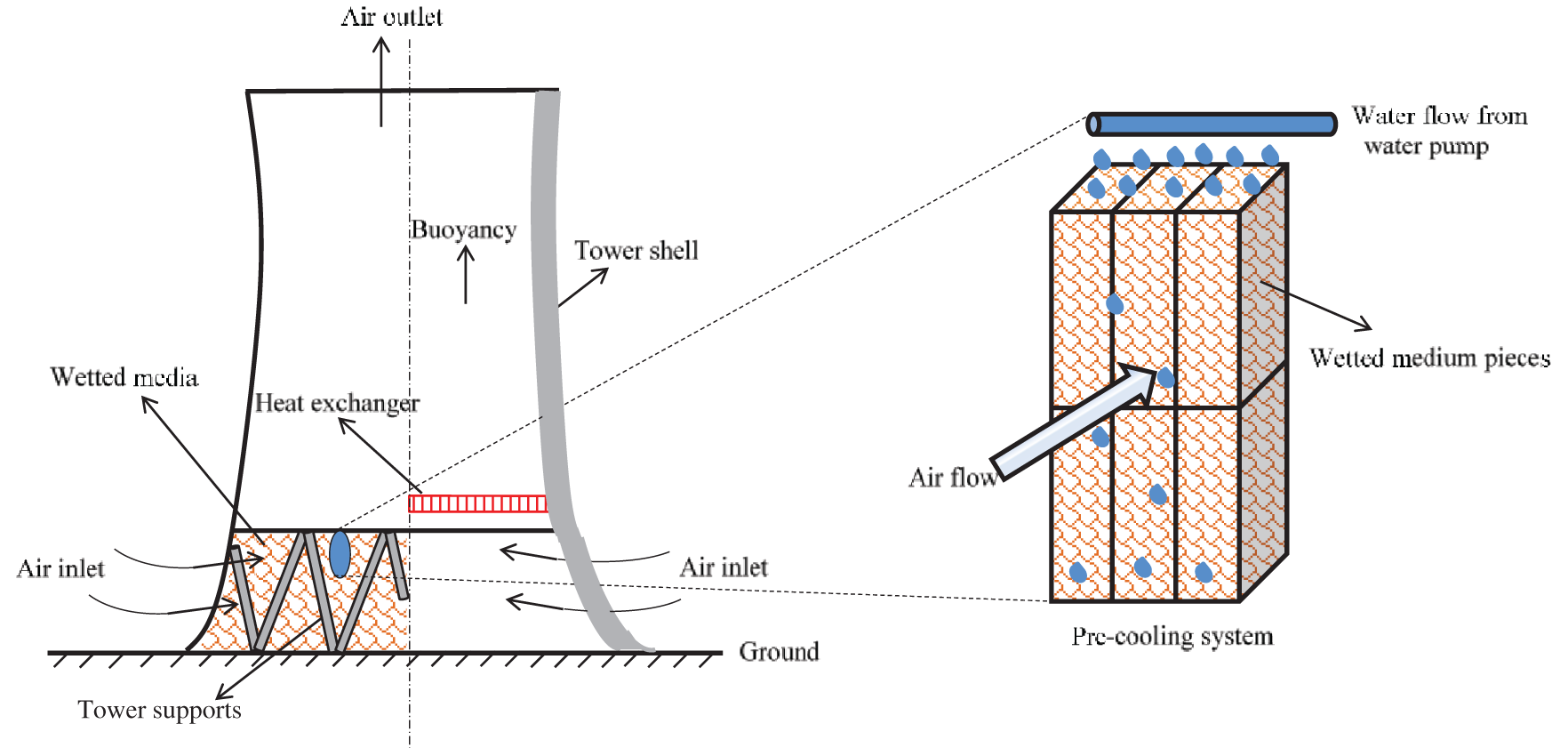
Figure 14: A NDDCT pre-cooled by wet media [105]
He et al. [106,107] selected four kinds of fills (two splash fills and two film fills) for direct evaporative cooling experiments, and obtained the calculation formulas of their cooling efficiency and pressure drop, which provides guideline for future research of pre-cooled NDDCTs. Subsequently, He et al. [108] utilized the obtained formula for calculating the performance of the wet media to simulate a NDDCT pre-cooled by wet media as well as discovered that the performance improvement of the NDDCT using film fill pre-cooling was better than that of the splash fills. The direct evaporative pre-cooling system could apparently increase the NDDCT’s heat transfer rate under the hot-dry condition. The heat rejection rate improvement of the NDDCT is 104% from 45 to 92 MW. He et al. [46,109] compared the parameters (heat transfer rate and water consumption) of a NDDCT, a pre-cooled NDDCT with wet media and a wet cooling tower by simulation. They discovered that the wet cooling tower had the highest heat rejection rate, the evaporative pre-cooling enhancement could increase 46% for the NDDCT in January. Comparing with the wet cooling tower, the pre-cooling system could save water by 70%. The inlet air pre-cooling of NDDCT is an effective measure to save water resources and enhance the thermal performance of the NDDCT in hot periods.
The wet media introduced an additional pressure drop, reducing the air flow through the tower [110]. Another method to enhance the tower’s cooling performance is spray pre-cooling, which has the advantages of simple structure and low maintenance cost [111]. The most important point is that the additional pressure drop caused by nozzle spray can be neglected. Fig. 15 shows a NDDCT pre-cooled by nozzle spray. The nozzles are installed at the NDDCT’s air inlet zone. The inlet air of NDDCT transfers heat with the water injected from the nozzle to decrease the inlet air temperature of NDDCT.
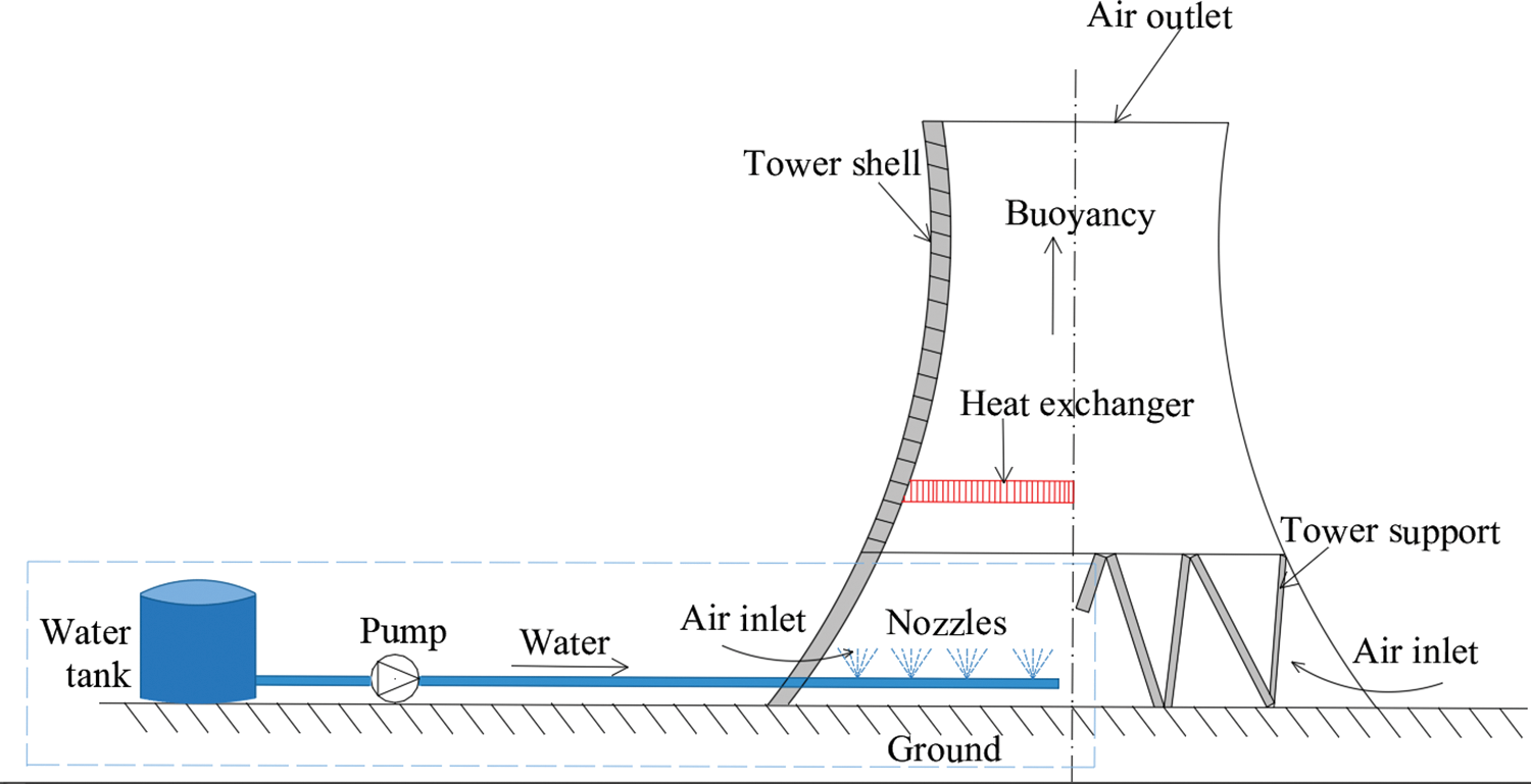
Figure 15: A NDDCT pre-cooled by nozzle spray [112]
Sadafi et al. [113] compared the performance of spray cooling system by saline water and pure water. The results showed that using saline water could increase the cooling efficiency on the region near the nozzle by 8.0%, and saline water was easier to achieve full evaporation than pure water. Subsequently, Sadafi et al. [114] compared the temperature distribution of five different nozzle arrangements, and found that the cooling efficiency could be improved by 2.9% under optimization of the nozzle arrangement. Sun et al. [115] developed a 3D model of NDDCT to study the effect of spray angle on the tower’s cooling performance and revealed the best injection angle for complete evaporation changed with the nozzle height. Then, Sun et al. [116] explored the nozzle’s arrangement of the pre-cooled NDDCT and found that a large number of nozzle arrangements could achieve better cooling effect; when five nozzles are adopted, the air temperature drop can reach to 6.3 K, and the cooling efficiency is 51.2%. Chen et al. [117] explored the influences of various environmental parameters, spray droplet size and the distance from the nozzle to the heat exchanger on the cooling performance of spray pre-cooled NDDCT. They revealed that the inlet air humidity had a great effect on the direct evaporative cooling process. With the humidity of the air increased, the spray droplets size and the height of nozzles need to be adjusted to achieve high cooling performance.
5.1 Direct Evaporative Cooling
Direct evaporative cooling is a cost-effective, energy-saving and efficient cooling method, which is widely used in industry production, especially in the field of electric power engineering. Researches about evaporative air conditioning, performance optimization of direct evaporative cooling in dry cooling system and gas turbine inlet air cooling have been in-depth and comprehensively reviewed. Through the review about the application of direct evaporative cooling in cooling towers of thermal power stations, the advantages of direct evaporative cooling technology are highlighted, and the shortcomings of existing research and technology are pointed out, which provides a reference for the further development of direct evaporative cooling.
5.2 Evaporative Cooling in Wet Cooling Towers
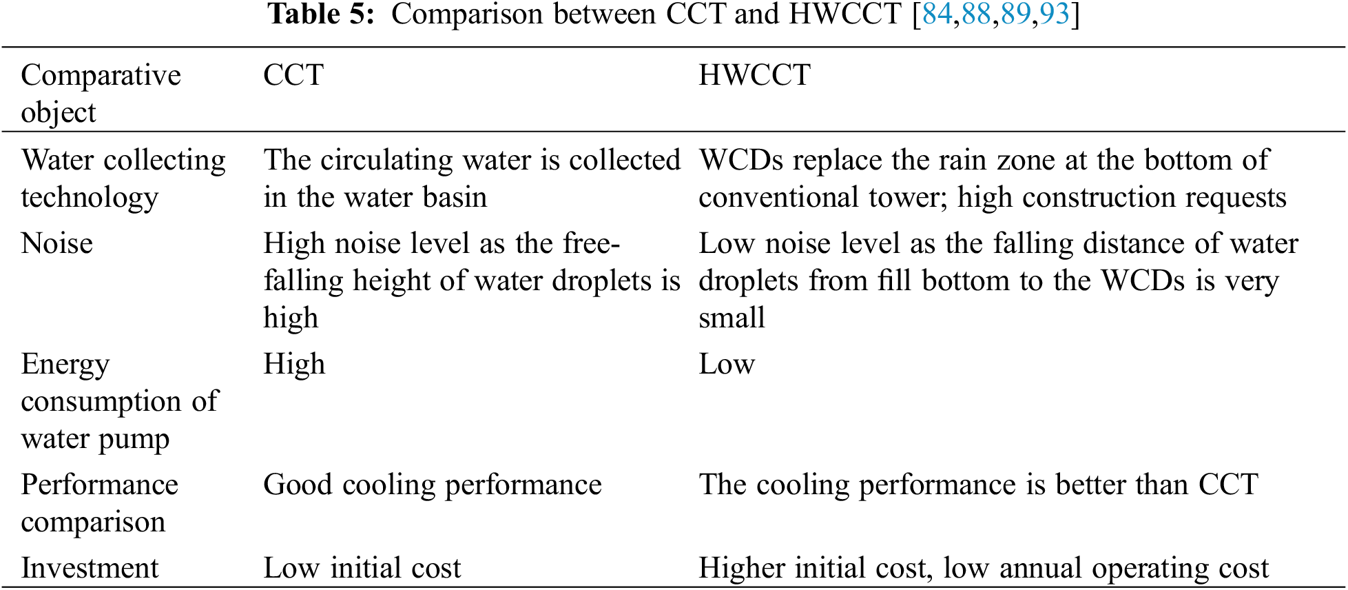
It was found that the current researches of wet cooling tower mainly focused on fills, water distribution, crosswind effect and the HWCCT. The future research of wet cooling tower will focus on how to optimize the fill arrangement and decrease the negative effects of crosswind in the process of tower design. The research of HWCCT will also be the future research highlights. If the HWCCT’s cooling performance can be improved, it will be the developing direction of wet cooling tower in the future. The comparison between CCT and HWCCT is shown in Table 5.
5.3 Evaporative Cooling in Air-Cooled Towers
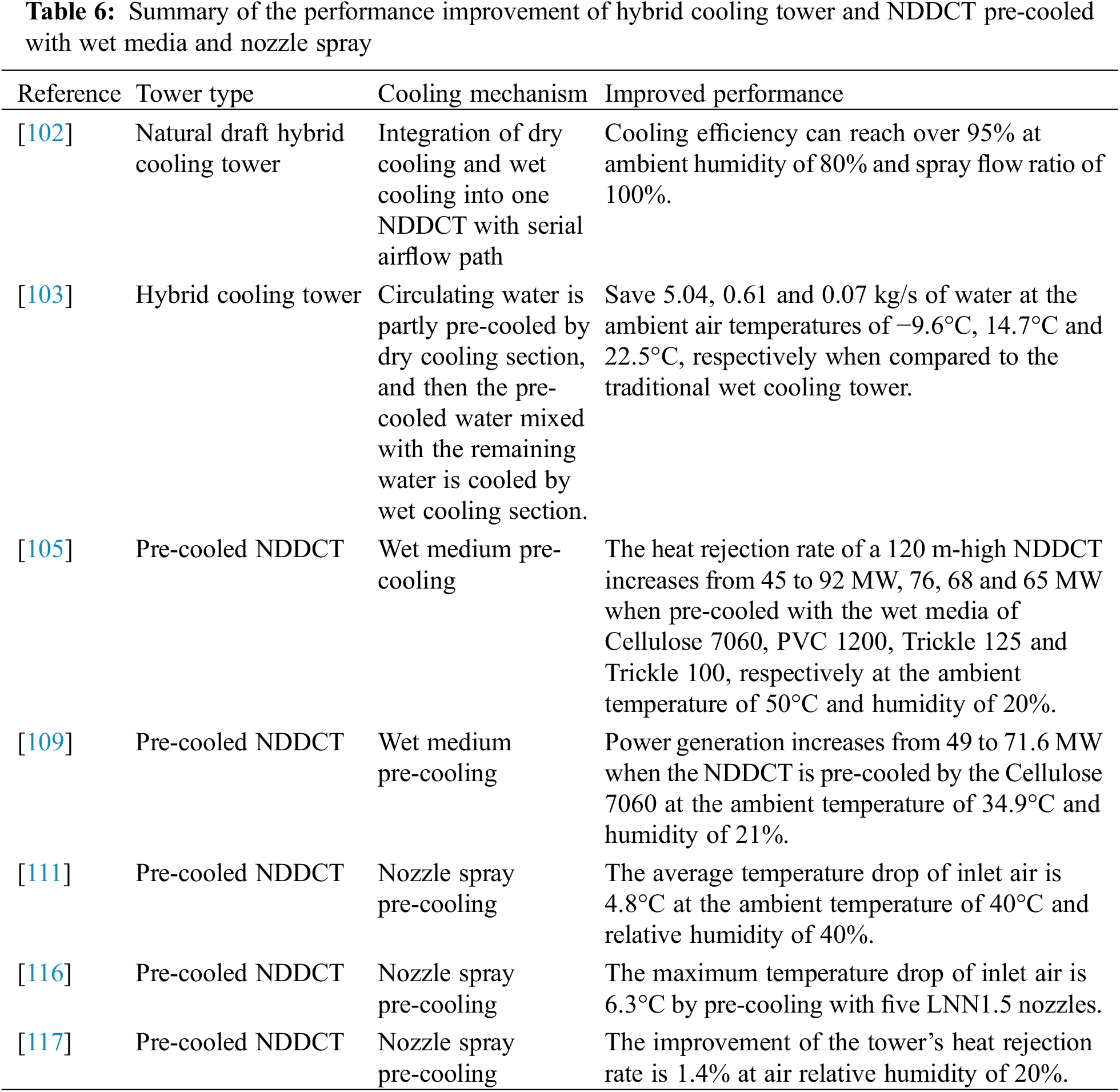
Three methods (i.e., increasing the ventilation, increasing the temperature difference and introducing evaporative cooling) can improve the heat rejection rate of air-cooled towers. The review focuses on hybrid cooling and inlet air pre-cooling. Researches revealed that the cooling performance of hybrid cooling towers is better when compared with the air-cooled towers, and further optimization research about hybrid towers will be a topic of high interest in the future. Table 6 summarizes the performance improvement of hybrid cooling tower and NDDCT pre-cooled with wet media and nozzle spray.
In hot periods, the cooling performance of NDDCTs can be enhanced by direct evaporative pre-cooling technology. The spray pre-cooling system will be a research hotspot because of its small additional pressure loss, simple structure, low maintenance requirement. Currently, researches about spray pre-cooling system mainly focus on the influence of water quality (saline water and pure water) on cooling performance and the optimization of nozzle arrangement. Further optimization of nozzle arrangement should consider ambient temperature, humidity, crosswind. Meanwhile, the economic analysis of pre-cooling system is a research gap.
6.1 Comparison of NDDCT, NDWCT and Pre-Cooled NDDCT with Wet Media
The air is driven into the tower by buoyancy force, and the circulating water in the heat exchanger is cooled by the air in a NDDCT. In a NDWCT, the air flows through the rain zone, wet medium zone and the spray zone sequentially, where the circulating water is exposed to direct contact with the air for heat exchange. In a pre-cooled NDDCT with wet media, the air is initially subjected to evaporative cooling in the wet medium zone, and then the cooled air absorbs heat from the circulating water in the heat exchanger of the tower. Comparing the performance of three typical towers (i.e., NDDCT, NDWCT and pre-cooled NDDCT with wet media) is the major objective of this case study. The case study selects the average monthly climate parameters of a typical hot-dry area in Australia in 2008 [46].
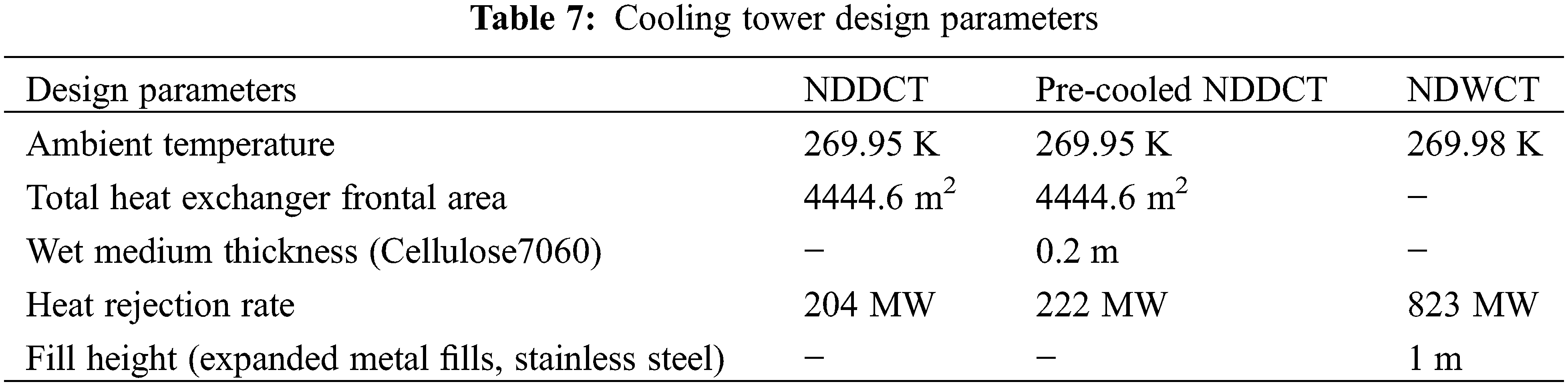
For the three types of towers discussed below, the following parameters are the same: the tower height, inlet diameter, outlet diameter are 130, 92 and 65 m, respectively; the ambient pressure is 100.9 kPa, the ambient humidity is 32.4%, the inlet water temperature is 323.15 K and its mass flow is 10000 kg/s. Table 7 lists the other design parameters. The tower dimensions are the same for the sake of comparison.
The mathematical model of a NDDCT is discussed in the reference [46]. In the direct evaporative pre-cooling process, the fills have two functions: one is to enlarge air-water contact surface; the other is to extend the contact time between air and water. According to the study of He et al. [106], this paper selects the film fill of CELdek7060 (Manufacturer: Munters Corp., Sweden) for pre-cooling study.
In the natural draft cooling tower, the energy equation and draft equation are coupled with each other. and the operation of the tower is simulated by a MATLAB iterative program. The MATLAB codes for iterative calculations of the NDDCT, the NDWCT and the pre-cooled NDDCT in Table 7 are developed for simulation. In the MATLAB algorithms, the fixed variables are the design parameters of the tower and heat exchanger, hot water flow rate, water inlet temperature and wet medium type and thickness. The thermal performance and water consumption of the three kinds of cooling towers are obtained by iterative calculations as reported in the reference [46]. Comparing the three kinds of cooling towers under the same design parameters and operation conditions, it was found that: (1) the cooling performance of NDDCT is improved by pre-cooling with wet media during hot periods while the NDWCT’s cooling performance is the highest. The tower’s heat rejection rate follows the order of NDWCT > Pre-cooled NDDCT > NDDCT; (2) the performance of three compared towers are remarkably influenced by the ambient parameters (i.e., temperature and humidity); (3) in January, the NDDCT’s heat rejection rate enhancement raises up to 46% from 93 to 136 MW owing to the pre-cooling system; (4) the pre-cooled NDDCT can save 70% water than the NDWCT [46].
It is proved that evaporative pre-cooling of NDDCTs is able to improve the cooling performance of a NDDCT during hot periods. Besides, the water consumption of a pre-cooled NDDCT is much lower than that of a NDWCT. In conclusion, evaporative pre-cooling technology has a prospective application in NDDCTs. Therefore, a further comparative study of the most frequently used pre-cooling methods, i.e., wet medium pre-cooling and nozzle spray pre-cooling, is carried out in Section 6.2.
6.2 Comparison of Pre-Cooled NDDCT with Wet Media and Nozzle Spray
According to Katsoulas et al. [118], the system with wet media is more efficient than that with spray, but wet media introduce the extra pressure drop resulting in decreasing the air flow of a natural draft cooling tower [55,119]. The performance of three types of towers (i.e., the NDDCT, the pre-cooled NDDCT using nozzle spray and the pre-cooled NDDCT using wet media) is discussed and analyzed in this section.
6.2.1 Geometry Model of the NDDCT
In this case, Table 8 lists the design parameters about the cooling tower and finned tube heat exchanger. The geometry model of the studied NDDCT as shown in Fig. 16.
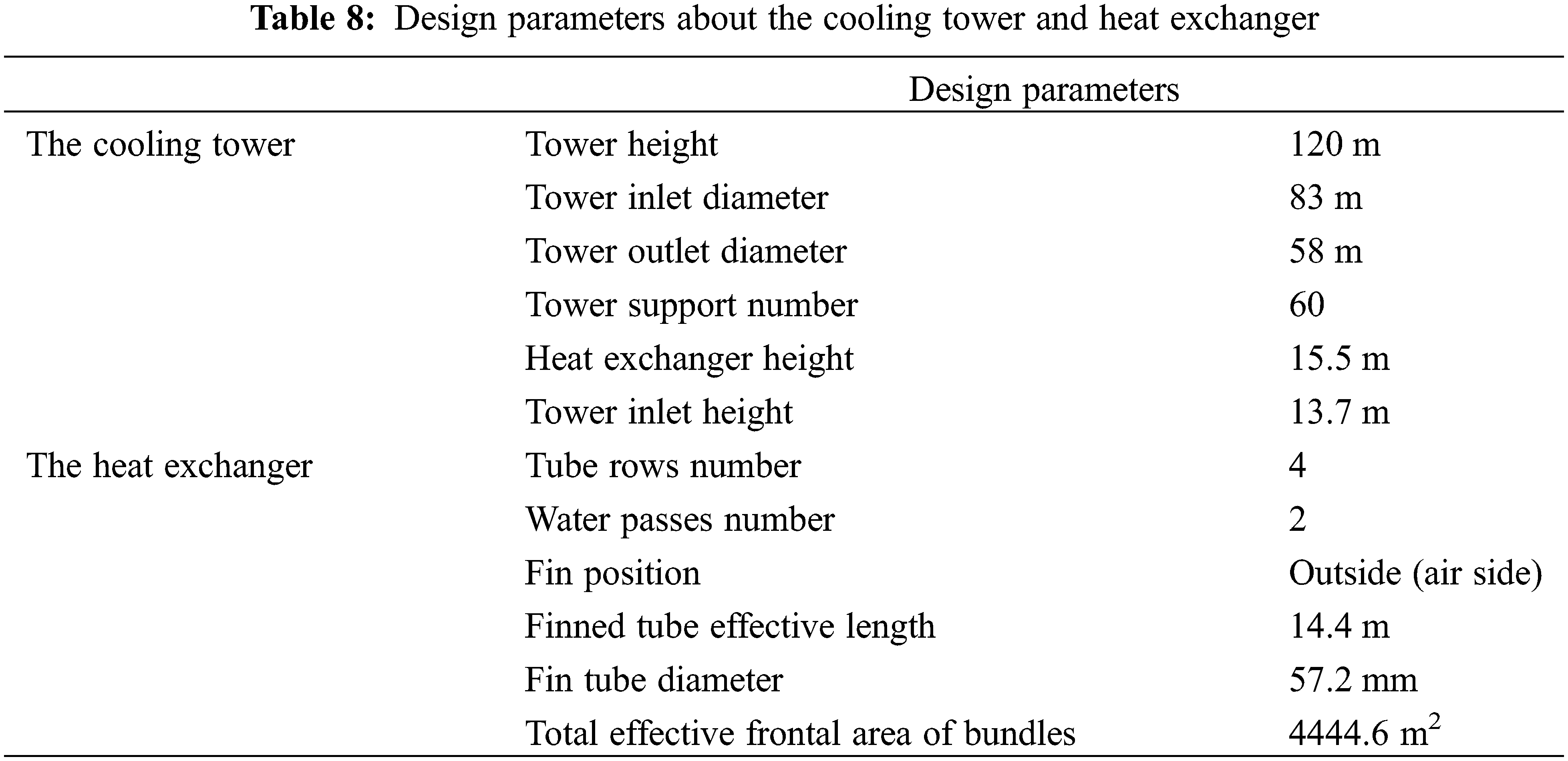
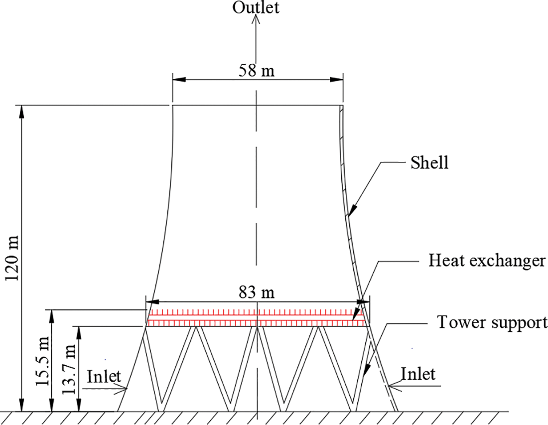
Figure 16: Geometry model of the studied NDDCT
6.2.2 Mathematical Model of the NDDCT
The NDDCT operation is controlled by energy and draft equations. The NDDCT’s energy equation is,
where Q1 is heat transfer rate, W; ma and mw are air mass flow and water mass flow, respectively, kg/s; cpa and cpw are air specific heat capacity and water specific heat capacity, respectively, J/(kg⋅K); T is temperature, K, the subscript ao, ai, wi and wo are referred to the outlet air, inlet air, inlet water and outlet water, respectively.
The heat transfer rate can be calculated by the overall heat transfer coefficient shown in Eq. (2).
where Q2 is heat transfer rate, W; A is heat exchanger area, m2; ΔTln is logarithmic mean temperature difference, K; U is overall heat transfer coefficient, W/(m2⋅K); FT is temperature correction factor; h is heat transfer coefficient, W/(m2⋅K), subscripts a and w are the air-side and water-side, respectively.
The hw (i.e., water-side heat transfer coefficient) can be calculated by Eq. (4) [120]:
Eq. (4) is applied to the ranges of Re (2300-106), Pr (0.5-104), d/L (0–1). The CD i.e., tube inside friction factor is,
where ε/d = 5.24 × 10⁻⁴, which is relative surface roughness of the investigated finned tube.
The heat transfer coefficient of air-side ha can be calculated by Eq. (6) [121]:
where Ny is the characteristic heat transfer parameter.
where μ is dynamic viscosity of air, kg/(m⋅s); Afr is total effective frontal area of heat exchanger, m2.
According to the buoyancy equals to the total flow resistances, the draft equation is,
where Δpa = ΣKρavuav2/2; Δp is flow resistances, Pa; ρavi and ρavo are inlet air density and outlet air density, kg/m3; H is the tower height, m. The flow resistances include tower support loss Δpts, the flow separation and redirection loss at the tower shell lower edge Δpct, the loss flow through the heat exchanger support Δphes which can be neglected, contraction loss Δpctc and expansion loss Δpcte at the heat exchanger, the frictional loss of heat exchanger Δphe, tower outflow kinetic energy loss Δpto. The empirical relations showed in reference [121] can be used to calculate the losses. The flow resistance can be expressed as the following:
The pressure drop can also be calculated by Eq. (11) according to reference [121]:
The subscript he indicates that all the loss coefficients are referred to the frontal area of the heat exchanger and the air mean density flowing through it.
The tower supports loss coefficient is affected by the characteristics of heat exchanger is [121],
The loss coefficient of cooling tower inlet can be calculated by Eq. (13), which based on the heat exchanger characteristics.
The expansion/contraction loss coefficient referred to the heat exchanger characteristics Kcte/Kctc can be calculated by Eqs. (14) and (15).
where Ae3 = Afr sinθ.
The contraction coefficient σc can be calculated by the formula according to reference [121],
The heat exchanger loss coefficient can be calculated by the formula according to reference [121],
where θm is the mean flow incidence angle that θm = 0.0019θ2 + 0.9133θ − 3.1558; The downstream loss coefficient is Kd, Kd = exp (5.488405 − 0.2131209θ + 3.533265 × 10⁻³θ2 − 0.2901016 × 10⁻⁴θ3); The inlet shrinkage loss coefficient is Kci, Kci = 0.05.
The correlation for Kto (i.e., loss coefficient of tower outlet) is,
where
The subscript 1, 3, 4, 5 and 6 are referred to the elevation of the ground level, the heat exchanger inlet, the heat exchanger outlet, the tower outlet and the ambient elevation that equals to tower height, respectively.
As mentioned in Section 4.3, the wet medium pre-cooling system could improve the thermal performance of a NDDCT during hot periods, but it introduces additional pressure drop, which is not beneficial to the enhancement of tower performance. Considering the trade-off between cooling efficiency and pressure drop of wet media, CELdek7060 media with a thickness of 0.2 m was selected to be arranged around the air inlet of the NDDCT, as shown in Fig. 14. The correlations of the fill for pressure drop and cooling efficiency are [106]:
where cooling efficiency η is defined as η = (Ta − Tai)/(Ta − Twb) × 100%, which indicates how close the exiting air gets to the state of saturation. le/l is a dimensionless parameter which represents the fill’s characteristic length determined by geometric structure, le is 0.002742 m for the CELdek7060, l (wet medium thickness) and qw (water flow rate) are 0.2 m and 0.00207 m3/s, respectively.
The purpose of the nozzle is also to enlarge air-water contact surface as well as to accelerate the evaporation of the droplets. Theoretically, the lowest temperature of the cooled air can reach its wet bulb temperature by using a spray precooling system. However, in practice, the cooling efficiency is much less than 100% due to the nozzle arrangement and other influencing factors. Sun et al. [116] carried out simulation research on the arrangement of nozzles in cooling tower. It was discovered that the spray pre-cooling system with 5 nozzles can reduce the inlet air temperature by 6.3°C, so that the cooling efficiency can reach 51.2%. In current study, we adopted the commercial nozzle LNN1.5 which is hollow and cone. The main parameters of LNN1.5 are speed of 22 m/s, cone angle of 39°, D32 (Sauter mean diameter) of 55 μm and Dv90 of 85 μm [116]. To pre-cool more air, the nozzles are arranged in a circle around the air inlet of the tower. For the arrangement of nozzles, to ensure that the droplets evaporate as much as possible and reduce the waste of water, the space between two nozzles is 5 m, and the radial distance from the nozzle to the center of the tower is 41.5 m. The empirical formula to calculate the cooling efficiency of nozzle spray system is,
where η is the cooling efficiency; me is the water evaporation rate, kg/s; ma is the air flow rate, kg/s; Twb is the wet bulb temperature of ambient air, K; Ds is horizontal arrangement distance between nozzles at the same height, m; R is the radial distance from the nozzle position to the tower center, m. In this paper, me is 41565.6 g/s, which is the spray water flow rate calculated by assuming the inlet air is cooled to the saturation under the design condition of the NDDCT; Ds is 5.0 m; R is 41.5 m. The air temperature after cooling can be obtained by Eq. (21) and the definition of cooling efficiency.
Case studies are investigated below to discuss and analyze the performance of three typical towers, i.e., the NDDCT, the pre-cooled NDDCT with wet media and nozzle spray, respectively. MATLAB code from reference [46] was adapted to study the operation of nozzle spray pre-cooling. The difference between wet medium and nozzle spray pre-cooling is the fact that the air-side flow resistance in nozzle spray system is negligible.
The case study selects the Naomao Lake’s weather data (Table 9) [122] in Xinjiang Province in the year of 2015.
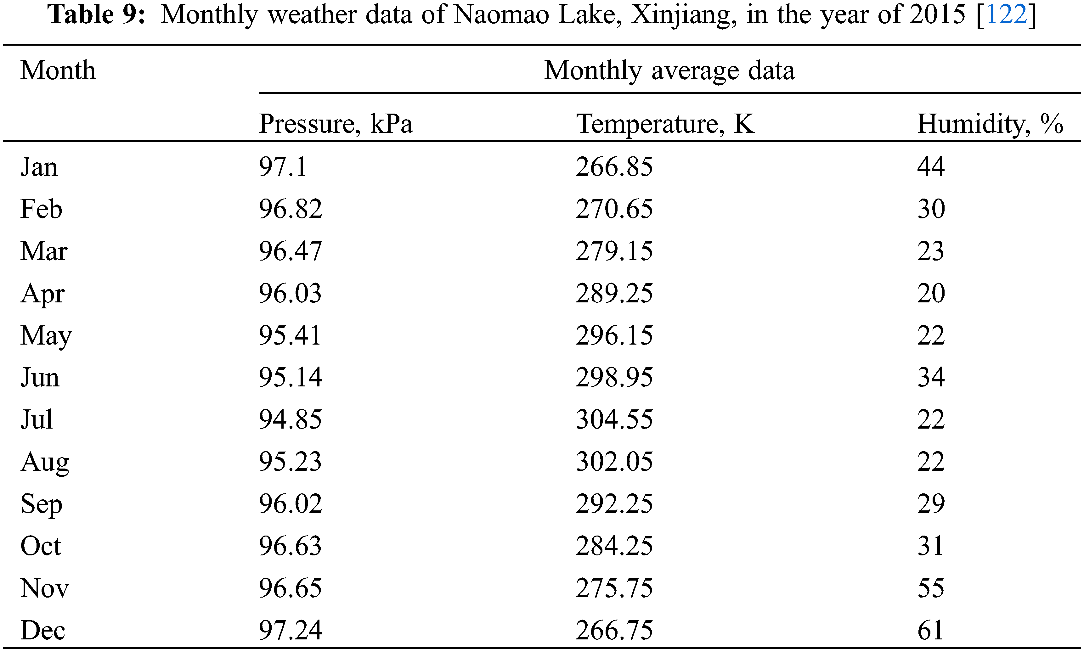
Fig. 17 illustrates the comparison of heat rejection rate and circular water exit temperature between the NDCCT, the pre-cooled NDDCT with nozzle spray and wet media, respectively. The lowest heat rejection rates of three kinds of tower occur in the hottest month (i.e., July). This is because the tower’s air flow rate becomes lower and the temperature difference (Twi-Tai) becomes smaller in the hottest month (i.e., July) when compared with the other months. The tower’s heat rejection rate follows the order of NDWCT > Pre-cooled NDDCT > NDDCT, which indicates that direct evaporative pre-cooling is able to enhance the performance of the NDDCT in hot-dry season.
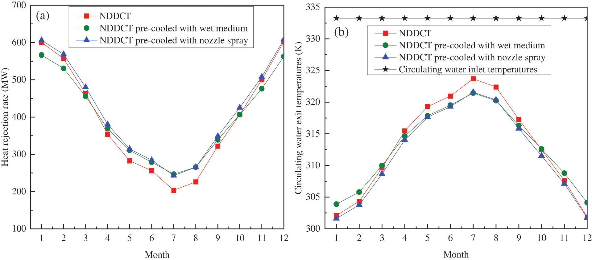
Figure 17: Performance comparison between the pre-cooled NDDCT with wet media and nozzle spray: (a) heat rejection rate and (b) circulating water exit temperature
In Fig. 17a, the wet medium pre-cooling technology can increase the NDDCT’s heat rejection rate in May, June, July and August. A clear improvement of the tower’s performance in July is estimated; it is reflected by the heat rejection increase of 21.2%. However, the spray pre-cooling technology can improve the NDDCT’s heat rejection rate in all year as well as increased by 19.4% in July.
The tower outlet water temperature directly affects the turbine back pressure of the thermal power plants. Fig. 17b describes the variation of the circulating water exit temperature of the three kinds of tower. The outlet temperature of circulating water of NDCCT is higher compared with NDDCT using wet media between April and September. The circulating water exit temperature is lower than that of the NDDCT throughout the year in the spray pre-cooled NDCCT. In July, the circulating water exit temperature of the NDDCT with nozzle spray and wet media decreases 2.2 and 2.4 K respectively when compared with the NDDCT.
The simulation study has the following conclusions: (1) The NDDCTs’ performance is affected by the variation of ambient humidity and temperature. (2) The NDDCTs’ cooling performance affected obviously by the evaporative pre-cooling in the hottest month. In July, the heat rejection rate has the highest improvement from 203.4 to 246.7 MW increasing about 21.2% in the pre-cooled NDDCT using wet media, followed by improvement from 203.4 to 242.9 MW increasing about 19.4% in the pre-cooled NDDCT with nozzle spray. (3) The rejection performance of NDDCTs can be improved using pre-cooling system with nozzle spray and wet media in hot periods. However, the wet medium pre-cooling is not recommended in Jan, Feb, Nov and Dec, because the NDDCT’s heat rejection rate is not improved in these months.
As mentioned in the reference [123], the standard coal consumption rate of a thermal power plant can be increased by 0.977 g/(kW⋅h) when the ambient temperature increases 1°C. Pre-cooling inlet air is able to reduce the temperature of the entering air of a NDDCT, which will in turn save coal consumption and reduce carbon emission of the served thermal power plant. The air temperature after pre-cooling can be obtained according to the cooling efficiency Eqs. (20) and (21). As shown in Fig. 18, the maximum temperature drops of 10.6°C and 17.6°C for the nozzle spray and wet-medium pre-cooling occur in July, which is the hottest month. Consequently, pre-cooled NDDCT using nozzle spray and wet media could save coal consumption up to 10.4 and 17.2 g/(kW⋅h), respectively, and reduces 27.6 and 45.7 g/(kW⋅h) of CO2 emissions in July.
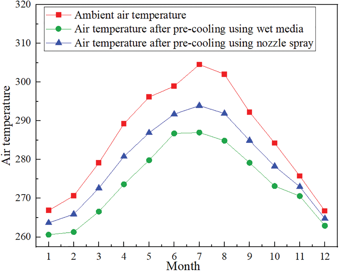
Figure 18: Air temperature after pre-cooling using wet media and nozzle spray
Direct evaporative pre-cooling can be applied for air-cooled towers in dry and hot areas. The pre-cooled NDDCT by nozzle spray is recommended to improve the cooling performance during hot periods since it has the advantage of performance improvement in all year. This technology is also used to direct air-cooled systems.
This paper reviews the application and research of evaporative cooling in power plants. The following conclusions can be obtained:
(1) There is a significant improvement on the thermal performance of a gas turbine cycle system using inlet air cooling technology. Evaporative cooling technology has poor enhancement on the thermal performance of the gas turbine cycle and has larger water consumption when compared to vapor compression cooling, absorption cooling and hybrid cooling technology. However, evaporative cooling technology is recommended at low ambient air temperature and low relative humidity conditions as it is cost effective.
(2) The research on wet cooling towers mainly focuses on fill, water distribution, cross-wind effect and HWCCT. The future research of wet cooling tower will focus on the optimization of fill arrangement, the control of the adverse effects of cross-wind and deep investigation of HWCCT.
(3) The hybrid cooling tower is a compromise between wet and dry cooling. Research shows that the cooling performance of hybrid cooling towers is better than that of the air-cooled towers, and further optimization research of the hybrid towers will be a topic with increasing interest in the future.
(4) Direct evaporative pre-cooling technology is an effective measure to improve the NDDCT’s cooling performance in hot periods. These cases discover that the cooling performance of three kinds of tower from high to low is NDWCT, pre-cooled NDDCT, NDDCT. The rejection performance of NDDCT can be improved using pre-cooling system with both wet media and nozzle spray in hot months. In July, the heat rejection rate has the highest improvement from 203.4 to 246.7 MW increasing about 21.2% in the pre-cooled NDDCT using wet media, followed by improvement from 203.4 to 242.9 MW increasing about 19.4% in the pre-cooled NDDCT using nozzle spray. The pre-cooling using nozzle spray is tend to enhance the tower performance in all months.
Future research will be a topic with increasing interest about the optimization of nozzle arrangement of the nozzle spray system. Besides, the ambient air temperature, humidity, crosswind and other influencing factors should be considered during the optimization of nozzle arrangement. Meanwhile, economic analysis of NDDCT with different evaporative pre-cooling systems are suggested to consider the water consumption, the increment of power output, the capital investment, etc.
Funding Statement: This work was supported by the Shandong Natural Science Foundation (Grant No. ZR2022ME008), the Shandong Provincial Science and Technology SMEs Innovation Capacity Improvement Project (2022TSGC2018), and the Shenzhen Science and Technology Program (KCXFZ20201221173409026). The financial supports from the “Young Scholars Program of Shandong University” (YSPSDU, No. 2018WLJH73), the Open Project of State Key Laboratory of Clean Energy Utilization, Zhejiang University (Program Number ZJUCEU2020011) and the Shandong Natural Science Foundation (Grant No. ZR2021ME118) are gratefully acknowledged.
Conflicts of Interest: The authors declare that they have no conflicts of interest to report regarding the present study.
References
1. He, S. Y. (2015). Performance improvement of natural draft dry cooling towers using wetted-medium evaporative pre-cooling (Ph.D. Thesis). University of Queensland, Australia. [Google Scholar]
2. Milosavljevic, N., Heikkilä, P. (2001). A comprehensive approach to cooling tower design. Applied Thermal Engineering, 21(9), 899–915. https://doi.org/10.1016/S1359-4311(00)00078-8 [Google Scholar] [CrossRef]
3. Xuan, Y. M., Xiao, F., Niu, X. F., Huang, X., Wang, S. W. (2012). Research and application of evaporative cooling in China: A review (I)–Research. Renewable and Sustainable Energy Reviews, 16(5), 3535–3546. https://doi.org/10.1016/j.rser.2012.01.052 [Google Scholar] [CrossRef]
4. Woods, J., Kozubal, E. (2013). A desiccant-enhanced evaporative air conditioner: Numerical model and experiments. Energy Conversion and Management, 61, 208–220. https://doi.org/10.1016/j.enconman.2012.08.007 [Google Scholar] [CrossRef]
5. Huang, X., Li, X., Sheng, X., Su, X. (2014). The research of the key problem of evaporative cooling system in dry areas subway. Energy Procedia, 61, 1965–1968. https://doi.org/10.1016/j.egypro.2014.12.053 [Google Scholar] [CrossRef]
6. He, Z., Cui, Y., Hellickson, M. A., Walker, J. N. (1987). Evaporative cooling system for agricultural production buildings. Transactions of the Chinese Society of Agricultural Engineering, 4, 99–109. [Google Scholar]
7. Watt, J. R. (1986). Evaporative air conditioning handbook. New York: Springer Berlin. [Google Scholar]
8. Ndukaife, T. A., Nnanna, A. G. A. (2018). Optimization of water consumption in hybrid evaporative cooling air conditioning systems for data center cooling applications. Heat Transfer Engineering, 40(7), 559–573. https://doi.org/10.1080/01457632.2018.1436418 [Google Scholar] [CrossRef]
9. Cui, Y. L., Zhu, J., Zoras, S., Liu, L. (2021). Review of the recent advances in dew point evaporative cooling technology: 3E (energy, economic and environmental) assessments. Renewable and Sustainable Energy Reviews, 148, 111345. https://doi.org/10.1016/j.rser.2021.111345 [Google Scholar] [CrossRef]
10. Yang, Y. F., Cui, G., Lan, C. Q. (2019). Developments in evaporative cooling and enhanced evaporative cooling-A review. Renewable and Sustainable Energy Reviews, 113, 109230. https://doi.org/10.1016/j.rser.2019.06.037 [Google Scholar] [CrossRef]
11. Al-Juwayhel, F., El-Dessouky, H., Ettouney, H., Al-Qattan, M. (2004). Experimental evaluation of one, two, and three stage evaporative cooling systems. Heat Transfer Engineering, 25(6), 72–86. https://doi.org/10.1080/01457630490486292 [Google Scholar] [CrossRef]
12. Cuce, P. M., Riffat, S. (2016). A state of the art review of evaporative cooling systems for building applications. Renewable and Sustainable Energy Reviews, 54, 1240–1249. https://doi.org/10.1016/j.rser.2015.10.066 [Google Scholar] [CrossRef]
13. Tejero-González, A., Franco-Salas, A. (2021). Direct evaporative cooling from wetted surfaces: Challenges for a clean air conditioning solution. Wiley Interdisciplinary Reviews: Energy and Environment, 11(3), e423. [Google Scholar]
14. Tejero-González, A., Franco-Salas, A. (2021). Optimal operation of evaporative cooling pads: A review. Renewable and Sustainable Energy Reviews, 151, 111632. https://doi.org/10.1016/j.rser.2021.111632 [Google Scholar] [CrossRef]
15. Sajjad, U., Abbas, N., Hamid, K., Abbas, S., Hussain, I. et al. (2021). A review of recent advances in indirect evaporative cooling technology. International Communications in Heat and Mass Transfer, 122(2), 105140. https://doi.org/10.1016/j.icheatmasstransfer.2021.105140 [Google Scholar] [CrossRef]
16. Sofia, E., Putra, N. (2020). Evaporative cooling innovations–A review. International Conference on Trends in Material Science and Inventive Materials, pp. 020036. Coimbatore, India. [Google Scholar]
17. Zhu, G., Wen, T., Wang, Q., Xu, X. (2022). A review of dew-point evaporative cooling: Recent advances and future development. Applied Energy, 312, 118785. https://doi.org/10.1016/j.apenergy.2022.118785 [Google Scholar] [CrossRef]
18. Huang, K. X. (2019). Research on energy saving application of evaporative cooling air conditioning system at airport (Ph.D. Thesis). Xi’an Polytechnic University, China. [Google Scholar]
19. Watt, J. R., Brown, W. K. (1997). Evaporative air conditioning handbook. USA: Fairmont Press Inc. [Google Scholar]
20. Hughes, B. R., Chaudhry, H. N., Ghani, S. A. (2011). A review of sustainable cooling technologies in buildings. Renewable and Sustainable Energy Reviews, 15(6), 3112–3120. https://doi.org/10.1016/j.rser.2011.03.032 [Google Scholar] [CrossRef]
21. Tang, L., Sun, D. F., Pan, J. P. (2017). Application of evaporative cooling ventilation technology to turbine house of one power plant in Pakistan. Procedia Engineering, 205, 902–907. https://doi.org/10.1016/j.proeng.2017.10.105 [Google Scholar] [CrossRef]
22. He, X. W., R, C. W., L, C. (2012). Selection and optimization of cooling and ventilation equipment for air-cooled inverter rooms. Heating Ventilating and Air Conditioning, 42(3), 32–36. [Google Scholar]
23. Xu, Y. Z. (2012). Application analysis of evaporative cooling air conditioner in hydropower plants. Hydropower and New Energy, 3, 72–74. [Google Scholar]
24. Li, C. C., Huang, X., Wang, C., Wu, S., Qv, Y. et al. (2011). Development of two-stage direct evaporative cooling air-conditioning units combined with filler and high pressure micro fog. Refrigeration and Air-Conditioning, 11(3), 116–120. [Google Scholar]
25. Wang, W. Z., Liu, Z. H., Liang, Z. F., Wang, R. X. (2008). Causes and countermeasures for the load limit in summer for 600 MW direct air-cooling units. Electric Power, 41(1), 56–59. [Google Scholar]
26. Du, X. Z., Li, Y. L., Wei, G. S., Yang, L. J., Yang, Y. P. (2010). Modeling on evaporative condenser for exhaust steam cooling of small-scale turbine. Journal of Thermal Science and Technology, 9(3), 200–205. [Google Scholar]
27. Wei, G. S., Ren, J. Q., Hong, W. P. (2012). Scheme design and analysis of variable condition of evaporative condenser for steam condensing of steam feeding water pump for 1000 MW air-cooled unit. Energy Procedia, 171, 177–1184. [Google Scholar]
28. Guo, S. J., Chen, G. B., Dong, X. J. (2004). Feasibility analysis of the application of evaporative condensers to cooling system in thermal power plant. Dong. Energy Engineering, 4, 53–57. [Google Scholar]
29. Bustamante, J. G., Rattner, A. S., Garimella, S. (2016). Achieving near-water-cooled power plant performance with air-cooled condensers. Applied Thermal Engineering, 105, 362–371. https://doi.org/10.1016/j.applthermaleng.2015.05.065 [Google Scholar] [CrossRef]
30. Wang, S. L., Zhao, W. S., Song, L. Q., Liu, Y. (2008). The study of spray humidification system used in direct air-cooled unit. Journal of Power Engineering, 28(5), 722–726. [Google Scholar]
31. Wang, S. L., Zhao, W. S., Liu, Y., Lin, A. B. (2008). Numerical study on spray humidification system used in the direct air-cooled unit. Proceedings of the CSEE, 28(29), 28–33. [Google Scholar]
32. Zhang, J. (2013). Study on flow and heat transfer characteristics of direct air-cooled condenser using spray cooling system (Ph.D. Thesis). University of Chinese Academy of Science, China. [Google Scholar]
33. Zhou, L. X., Zhang, Q., Li, H. H., Zhou, S. C., Li, P. (2010). Numerical simulation of longitudinal double-row arrangement of spray humidification system in the direct air-cooling unit. Electric Power Construction, 31(9), 98–101. [Google Scholar]
34. Hui, X. S. (2013). The structural optimization for spray humidification system of direct air-cooling unit (Master Thesis). North China Electric Power University, China. [Google Scholar]
35. Zheng, W. H., Li, B. Y., Cai, J. J., Li, Y. M. (2021). Effects of continuous wet weather on the microclimate environment of electrical power plants. Sustainable Energy Technologies and Assessments, 43, 100989. https://doi.org/10.1016/j.seta.2020.100989 [Google Scholar] [CrossRef]
36. Sanaye, S., Amani, M., Amani, P. (2018). 4E modeling and multi-criteria optimization of CCHPW gas turbine plant with inlet air cooling and steam injection. Sustainable Energy Technologies and Assessments, 29, 70–81. https://doi.org/10.1016/j.seta.2018.06.003 [Google Scholar] [CrossRef]
37. Mohapatra, A. K., Sanjay (2013). Analytical investigation of parameters affecting the performance of cooled gas turbine cycle with evaporative cooling of inlet air. Arabian Journal for Science and Engineering, 38, 1587–1597. https://doi.org/10.1007/s13369-013-0598-x [Google Scholar] [CrossRef]
38. Mohapatra, A. K., Sanjay (2015). Comparative analysis of inlet air cooling techniques integrated to cooled gas turbine plant. Journal of the Energy Institute, 88(3), 344–358. https://doi.org/10.1016/j.joei.2014.07.006 [Google Scholar] [CrossRef]
39. Najjar, Y. S. H. (1996). Enhancement of performance of gas turbine engines by inlet air cooling and cogeneration system. Applied Thermal Engineering, 16(2), 163–173. https://doi.org/10.1016/1359-4311(95)00047-H [Google Scholar] [CrossRef]
40. Najjar, Y. S. H., Abubaker, A. M. (2015). Indirect evaporative combined inlet air cooling with gas turbines for green power technology. International Journal of Refrigeration, 59, 233–250. https://doi.org/10.1016/j.ijrefrig.2015.07.001 [Google Scholar] [CrossRef]
41. Shukla, A. K., Singh, O. (2016). Performance evaluation of steam injected gas turbine based power plant with inlet evaporative cooling. Applied Thermal Engineering, 102, 454–464. https://doi.org/10.1016/j.applthermaleng.2016.03.136 [Google Scholar] [CrossRef]
42. Shukla, A. K., Singh, O. (2017). Thermodynamic analysis of steam-injected gas turbine cycle power plant with inlet air cooling. International Journal of Ambient Energy, 38(6), 556–566. https://doi.org/10.1080/01430750.2016.1155495 [Google Scholar] [CrossRef]
43. Shukla, A. K., Singh, O. (2017). Thermodynamic investigation of parameters affecting the execution of steam injected cooled Gas turbine based combined cycle power plant with vapor absorption inlet air cooling. Applied Thermal Engineering, 122, 380–388. https://doi.org/10.1016/j.applthermaleng.2017.05.034 [Google Scholar] [CrossRef]
44. Barakat, S., Ramzy, A., Hamed, A. M., El-Emam, S. H. (2019). Augmentation of gas turbine performance using integrated EAHE and fogging inlet air cooling system. Energy, 189, 116133. https://doi.org/10.1016/j.energy.2019.116133 [Google Scholar] [CrossRef]
45. Zhao, Z. G. (1997). Cooling tower. Beijing: China Water Power Press. [Google Scholar]
46. He, S. Y., Gurgenci, H., Guan, Z. Q., Hooman, K., Zou, Z. et al. (2016). Comparative study on the performance of natural draft dry, pre-cooled and wet cooling towers. Applied Thermal Engineering, 99, 103–113. https://doi.org/10.1016/j.applthermaleng.2016.01.060 [Google Scholar] [CrossRef]
47. Asvapoositkul, W., Kuansathan, M. (2014). Comparative evaluation of hybrid (dry/wet) cooling tower performance. Applied Thermal Engineering, 71(1), 83–93. https://doi.org/10.1016/j.applthermaleng.2014.06.023 [Google Scholar] [CrossRef]
48. Nourani, Z., Naserbegi, A., Tayyebi, S., Aghaie, M. (2019). Thermodynamic evaluation of hybrid cooling towers based on ambient temperature. Thermal Science and Engineering Progress, 14, 100406. https://doi.org/10.1016/j.tsep.2019.100406 [Google Scholar] [CrossRef]
49. Kloppers, J. C., Kroger, D. G. (2005). Influence of temperature inversions on wet-cooling tower performance. Applied Thermal Engineering, 25(8–9), 1325–1336. https://doi.org/10.1016/j.applthermaleng.2004.09.003 [Google Scholar] [CrossRef]
50. Wan, D. W., Gao, S. S., Liu, M. H., Li, S. G., Zhao, Y. B. (2020). Effect of cooling water salinity on the cooling performance of natural draft wet cooling tower. International Journal of Heat and Mass Transfer, 161, 120257. https://doi.org/10.1016/j.ijheatmasstransfer.2020.120257 [Google Scholar] [CrossRef]
51. Zhou, X. H., Wang, W. J., Chen, L., Yang, L. J., Du, X. Z. (2021). Numerical investigation on novel water distribution for natural draft wet cooling tower. International Journal of Heat and Mass Transfer, 181, 121886. https://doi.org/10.1016/j.ijheatmasstransfer.2021.121886 [Google Scholar] [CrossRef]
52. Zhang, Z. Q., Gao, M., Wang, M. Y., Guan, H. J., Dang, Z. G. et al. (2019). Field test study on thermal and ventilation performance for natural draft wet cooling tower after structural improvement. Applied Thermal Engineering, 155, 305–312. https://doi.org/10.1016/j.applthermaleng.2019.04.015 [Google Scholar] [CrossRef]
53. Williamson, N., Armfield, S., Behnia, M. (2008). Numerical simulation of flow in a natural draft wet cooling tower-the effect of radial thermofluid fields. Applied Thermal Engineering, 28(2–3), 178–189. https://doi.org/10.1016/j.applthermaleng.2007.03.036 [Google Scholar] [CrossRef]
54. Pawel, R., Marek, L., Renata, K. (2019). Optimization of thermal-flow processes in a system of conjugate cooling towers. Heat Transfer Engineering, 41(22), 1938–1948. [Google Scholar]
55. He, S. Y., Gurgenci, H., Guan, Z. Q., Huang, X., Lucas, M. (2015). A review of wetted media with potential application in the pre-cooling of natural draft dry cooling towers. Renewable and Sustainable Energy Reviews, 44, 407–422. https://doi.org/10.1016/j.rser.2014.12.037 [Google Scholar] [CrossRef]
56. Kloppers, J. C., Kroger, D. G. (2003). Loss coefficient correlation for wet-cooling tower fills. Applied Thermal Engineering, 23(17), 2201–2211. https://doi.org/10.1016/S1359-4311(03)00201-1 [Google Scholar] [CrossRef]
57. Tiwari, A. K., Jain, S., Karmakar, S. (2021). An improved three-dimensional numerical model of a v-bar splash fill in a wet cooling tower. International Communications in Heat and Mass Transfer, 128, 105617. https://doi.org/10.1016/j.icheatmasstransfer.2021.105617 [Google Scholar] [CrossRef]
58. Mirskyand, G. R., Bauthier, J. (1984). Evolution of cooling tower fill. Cooling Technol Institute Journal, 14, 12–19. [Google Scholar]
59. Yan, M. X., He, S. Y., Li, N., Huang, X., Gao, M. (2021). Experimental investigation on a novel arrangement of wet medium for evaporative cooling of air. International Journal of Refrigeration, 124, 64–74. https://doi.org/10.1016/j.ijrefrig.2020.12.014 [Google Scholar] [CrossRef]
60. Zhang, D. Y., Zhang, Z. Q., Han, Q., Wu, F. X., He, S. Y. (2021). Numerical simulation on synergetic optimization of non-equidistant fillings and non-uniform water distribution for wet cooling towers. International Journal of Heat and Mass Transfer, 179, 121676. https://doi.org/10.1016/j.ijheatmasstransfer.2021.121676 [Google Scholar] [CrossRef]
61. Zhou, Y., Wang, K., Gao, M., Dang, Z. G., He, S. Y. et al. (2018). Experimental study on the drag characteristic and thermal performance of non-uniform fillings for wet cooling towers under crosswind conditions. Applied Thermal Engineering, 40, 398–405. https://doi.org/10.1016/j.applthermaleng.2018.05.071 [Google Scholar] [CrossRef]
62. Lyu, D. Q., Sun, F. Z., Zhao, Y. B. (2017). Impact mechanism of different fill layout patterns on the cooling performance of the wet cooling tower with water collecting devices. Applied Thermal Engineering, 110, 1389–1400. https://doi.org/10.1016/j.applthermaleng.2016.08.190 [Google Scholar] [CrossRef]
63. Singh, K., Das, R. (2016). An experimental and multi-objective optimization study of a forced draft cooling tower with different fills. Energy Conversion and Management, 111, 417–430. https://doi.org/10.1016/j.enconman.2015.12.080 [Google Scholar] [CrossRef]
64. Gao, M., Zhang, L., Wang, N. N., Shi, Y. T., Sun, F. Z. (2016). Influence of non-uniform layout fillings on thermal performance for wet cooling tower. Applied Thermal Engineering, 93, 549–555. https://doi.org/10.1016/j.applthermaleng.2015.09.054 [Google Scholar] [CrossRef]
65. Zhou, Y. S., Zhu, X., Ding, X. (2018). Theoretical investigation on thermal performance of new structure closed wet cooling tower. Heat Transfer Engineering, 39(5), 460–472. https://doi.org/10.1080/01457632.2017.1312899 [Google Scholar] [CrossRef]
66. Zhang, H. C. (2013). Numerical simulation of natural ventilation countercurrent wet cooling tower and optimization of water distribution system (Master Thesis). North China Electric Power University, Beijing, China. [Google Scholar]
67. Li, H. W., Duan, W. B., Wang, S. B., Zhang, X. L., Sun, B. (2018). Numerical simulation study on different spray rates of three-area water distribution in wet cooling tower of fossil-fuel power station. Applied Thermal Engineering, 130, 1558–1567. https://doi.org/10.1016/j.applthermaleng.2017.11.107 [Google Scholar] [CrossRef]
68. Zhao, S. A., Liao, N. P., Xu, M. (2003). Two dimensional optimal design of counter flow natural draught cooling tower. Journal of Hydraulic Engineering, 10, 26–31+37. [Google Scholar]
69. Zou, J., He, S. Y., Long, G. Q., Sun, F. Z., Gao, M. (2018). Field test on ventilation performance for high level water collecting wet cooling tower under crosswind conditions. Applied Thermal Engineering, 133, 439–445. https://doi.org/10.1016/j.applthermaleng.2018.01.065 [Google Scholar] [CrossRef]
70. Al-Waked, R. (2010). Crosswinds effect on the performance of natural draft wet cooling towers. International Journal of Thermal Sciences, 49(1), 218–224. https://doi.org/10.1016/j.ijthermalsci.2009.07.012 [Google Scholar] [CrossRef]
71. Al-Waked, R., Behnia, M. (2006). CFD simulation of wet cooling towers. Applied Thermal Engineering, 26(4), 382–395. https://doi.org/10.1016/j.applthermaleng.2005.06.018 [Google Scholar] [CrossRef]
72. Gao, M., Sun, F. Z., Wang, K., Shi, Y. T., Zhao, Y. B. (2008). Experimental research of heat transfer performance on natural draft counter flow wet cooling tower under cross-wind conditions. International Journal of Thermal Sciences, 47(7), 935–941. https://doi.org/10.1016/j.ijthermalsci.2007.07.010 [Google Scholar] [CrossRef]
73. Chen, X. H., Sun, F. Z., Chen, Y. L., Yuan, W. (2021). The effects of different air channels’ layout patterns on heat transfer and ventilation characteristics of wet cooling tower under crosswind conditions. Journal of Thermal Science and Engineering Applications, 13(6), 1–27. https://doi.org/10.1115/1.4050664 [Google Scholar] [CrossRef]
74. Gao, M., Sun, F. Z., Wang, N. N., Zhao, Y. B. (2014). Experimental research on circumferential inflow air and vortex distribution for wet cooling tower under crosswind conditions. Applied Thermal Engineering, 64(1–2), 93–100. https://doi.org/10.1016/j.applthermaleng.2013.12.023 [Google Scholar] [CrossRef]
75. Zhang, Z. Q., Wang, M. Y., Liu, Y., Gao, M., He, S. Y. (2020). An exploratory research on performance improvement of super-large natural draft wet cooling tower based on the reconstructed dry-wet hybrid rain zone, Part 2: Crosswind effects. International Journal of Heat and Mass Transfer, 160, 118465. https://doi.org/10.1016/j.ijheatmasstransfer.2020.120225 [Google Scholar] [CrossRef]
76. Liu, D. M. (2015). Three-dimensional numerical study on the influence of crosswind on the performance of natural ventilation wet cooling tower (Master Thesis). Beijing Jiaotong University, China. [Google Scholar]
77. Jiang, B., Zhou, L. X. (2010). Numerical study of installing cross-windbreak on natural draft cooling tower. Turbine Technology, 52(3), 165–168+172. [Google Scholar]
78. Chen, X. H., Sun, F. Z., Chen, Y. L., Gao, M. (2019). New retrofit method to improve the thermal performance of natural draft wet cooling towers based on the reconstruction of the aerodynamic field. International Journal of Heat and Mass Transfer, 132, 671–680. https://doi.org/10.1016/j.ijheatmasstransfer.2018.12.047 [Google Scholar] [CrossRef]
79. Kashani, M. M. H., Dobrego, K. V. (2015). Effect of inlet window deflectors on the performance of a natural-draft cooling tower subjected to crosswinds. Heat Transfer Engineering, 37(15), 1293–1301. https://doi.org/10.1080/01457632.2015.1119618 [Google Scholar] [CrossRef]
80. Al-Waked, R., Behnia, M. (2007). Enhancing performance of wet cooling towers. Energy Conversion and Management, 48(10), 2638–2648. https://doi.org/10.1016/j.enconman.2007.04.018 [Google Scholar] [CrossRef]
81. Chen, Y. L., Sun, F. Z., Wang, H. G., Mu, N., Gao, M. (2011). Experimental research of the cross walls effect on the thermal performance of wet cooling towers under crosswind conditions. Applied Thermal Engineering, 31(7–18), 4007–4013. https://doi.org/10.1016/j.applthermaleng.2011.08.001 [Google Scholar] [CrossRef]
82. Chen, X. H., Sun, F. Z., Chen, Y. L., Gao, M. (2019). Novel method for improving the cooling performance of natural draft wet cooling towers. Applied Thermal Engineering, 147, 562–570. https://doi.org/10.1016/j.applthermaleng.2018.10.076 [Google Scholar] [CrossRef]
83. Zhao, Y. B., Sun, F. Z., Long, G. Q., Huang, X. F., Huang, W. Q. et al. (2016). Comparative study on the cooling characteristics of high level water collecting natural draft wet cooling tower and the usual cooling tower. Energy Conversion and Management, 116, 150–164. https://doi.org/10.1016/j.enconman.2016.02.071 [Google Scholar] [CrossRef]
84. Wu, Y. Y. (2015). Numerical calculation research on high-level water collecting cooling tower and optimization of water collector (Master Thesis). Shandong University, China. [Google Scholar]
85. He, S. Y., Zhang, Z. Y., Gao, M., Sun, F. Z., Lucas, M. et al. (2019). Experimental study on the air-side flow resistance of different water collecting devices for wet cooling tower applications. Journal of Wind Engineering and Industrial Aerodynamics, 190, 53–60. https://doi.org/10.1016/j.jweia.2019.04.012 [Google Scholar] [CrossRef]
86. Claude, J. (1982). Principle of a general hydraulic circuit in atmosphere cooling towers with a recovery system. Proceedings of 3th IAHR Cooling Tower Workshop Symposium, Budapest, Hungary. [Google Scholar]
87. Vauzanges, M. E., Rribier, J. G. (1982). Cooling towers with cooled collectors. Proceedings of 3th IAHR Cooling Tower Workshop Symposium, Budapest, Hungary. [Google Scholar]
88. Jin, X. Q., Xie, H. Y., Ni, J. L., Wang, Z. S. (1993). Design of the high level water collecting cooling tower. Electric Power, 6, 39–43. [Google Scholar]
89. Li, Y. (2015). Comparison of economic efficiency of conventional cooling tower and high level water collecting wet cooling tower. Huadian Technology, 37(7), 38–39+42+77. [Google Scholar]
90. Li, Z. H., Zhang, G. Z., Wang, Z. Q. (2017). Application research on energy saving technology of high cooling tower in jiujiang power plant. Jiangxi Electric Power, 41(2), 49–51. [Google Scholar]
91. Gao, M., Zou, J., He, S. Y., Sun, F. Z. (2018). Thermal performance analysis for high level water collecting wet cooling tower under crosswind conditions. Applied Thermal Engineering, 136, 568–575. https://doi.org/10.1016/j.applthermaleng.2018.03.043 [Google Scholar] [CrossRef]
92. Dang, Z. G., Gao, M., Long, G. Q., Zou, J., He, S. Y. et al. (2019). Crosswind influence on cooling capacity in different zones for high level water collecting wet cooling towers based on field test. Journal of Wind Engineering and Industrial Aerodynamics, 190, 134–142. https://doi.org/10.1016/j.jweia.2019.04.014 [Google Scholar] [CrossRef]
93. Chen, G. G., Zhao, Y. B., Li, W. D., Ge, W. J. (2019). The efficiency of high-level water collecting cooling tower with the installation of cross wall affect by the evolution of aerodynamic field. Applied Thermal Engineering, 161, 114181. https://doi.org/10.1016/j.applthermaleng.2019.114181 [Google Scholar] [CrossRef]
94. Chen, G. G., Zhao, Y. B., Li, W. D., Ge, W. J. (2020). Critical guidelines to cope with the adverse impacts of the inner peripheral vortex in the high-level water collecting natural draft wet cooling tower. Applied Thermal Engineering, 168, 114819. https://doi.org/10.1016/j.applthermaleng.2019.114819 [Google Scholar] [CrossRef]
95. Lyu, D. Q., Sun, F. Z., Zhao, Y. B. (2016). Experimental study on the air flow field in the water collecting devices. Applied Thermal Engineering, 105, 961–970. https://doi.org/10.1016/j.applthermaleng.2016.01.124 [Google Scholar] [CrossRef]
96. He, S. Y., Zhang, G. H., Gao, M., Sun, F. Z., Huang, X. (2019). Wind tunnel test on the flow resistance of U-type water collecting devices for natural draft wet cooling towers. Journal of Wind Engineering and Industrial Aerodynamics, 186, 234–240. https://doi.org/10.1016/j.jweia.2019.01.008 [Google Scholar] [CrossRef]
97. Chen, L. J., Mi, L. J., Xv, C., Lei, Y. (2010). Development and analysis of direct and indirect air cooling under new situation. Power System Engineering, 26(6), 5–6+9. [Google Scholar]
98. Gnielinski, V. (1975). Neue gleichungen fürden wärme-undden stoffübergang in turbulent durchströmten rohren und kanälen. Forschung Im Ingenieurwesen A, 41(1), 8–16. https://doi.org/10.1007/BF02559682 [Google Scholar] [CrossRef]
99. Tao, T., Xu, J. Q., Jin, S. X., Wei, H. Q. (2013). Study on operating characteristics of power plant with dry and wet cooling systems. Energy and Power Engineering, 5(4), 651–656. https://doi.org/10.4236/epe.2013.54B126 [Google Scholar] [CrossRef]
100. Heyns, J. A. (2008). performance characteristics of an air-cooled steam condenser incorporating a hybrid (dry/wet) dephlegmator (Master Thesis). Stellenbosch University, South Africa. [Google Scholar]
101. Hu, H. M., Li, Z. G., Jiang, Y. Y., Du, X. Z. (2018). Thermodynamic characteristics of thermal power plant with hybrid (dry/wet) cooling system. Energy, 147, 729–741. https://doi.org/10.1016/j.energy.2018.01.074 [Google Scholar] [CrossRef]
102. Huang, X. W., Wang, W. J., Chen, L., Yang, L. J., Du, X. Z. (2020). Performance analyses of a combined natural draft hybrid cooling system with serial airflow path. International Journal of Heat and Mass Transfer, 159, 120073. https://doi.org/10.1016/j.ijheatmasstransfer.2020.120073 [Google Scholar] [CrossRef]
103. Hu, H. M., Jiang, Y. Y., Guo, G. H., Li, Z. G. (2018). Thermodynamic coupling characteristics in hybrid (dry/wet) cooling system. International Journal of Green Energy, 15(9), 532–543. https://doi.org/10.1080/15435075.2018.1489253 [Google Scholar] [CrossRef]
104. Xia, L., Li, J. H., Wei, M., Gurgenci, H., Guan, Z. Q. et al. (2016). Water consumption comparison between a natural draft wet cooling tower and a natural draft hybrid cooling tower an annual simulation for luoyang conditions. Heat Transfer Engineering, 38(11–12), 1034–1043. https://doi.org/10.1080/01457632.2016.1216975 [Google Scholar] [CrossRef]
105. He, S. Y., Xu, Y., Zhang, G. H., Hooman, K., Gao, M. (2017). Selection of wetted media for pre-cooling of air entering natural draft dry cooling towers. Applied Thermal Engineering, 114, 857–863. https://doi.org/10.1016/j.applthermaleng.2016.11.179 [Google Scholar] [CrossRef]
106. He, S. Y., Guan, Z. Q., Gurgenci, H., Hooman, K., Lu, Y. S. et al. (2014). Experimental study of film media used for evaporative pre-cooling of air. Energy Conversion and Management, 87, 874–884. https://doi.org/10.1016/j.enconman.2014.07.084 [Google Scholar] [CrossRef]
107. He, S. Y., Guan, Z. Q., Gurgenci, H., Hooman, K., Lu, Y. S. et al. (2015). Experimental study of the application of two trickle media for inlet air pre-cooling of natural draft dry cooling towers. Energy Conversion and Management, 89, 644–654. https://doi.org/10.1016/j.enconman.2014.10.031 [Google Scholar] [CrossRef]
108. He, S. Y., Sun, F. Z., Gao, M., Zhao, Y. B. (2017). Performance improvement of natural draft dry cooling towers using wetted-medium evaporative pre-cooling. Acta Energiae Solaris Sinica, 38(11), 3022–3028. [Google Scholar]
109. Zhang, G. H., He, S. Y., Zhang, Z. Y., Xu, Y., Wang, R. (2017). Economic analyses of natural draft dry cooling towers pre-cooled using wetted media. Procedia Engineering, 205, 423–430. https://doi.org/10.1016/j.proeng.2017.10.393 [Google Scholar] [CrossRef]
110. He, S. Y., Gurgenci, H., Guan, Z. Q., Alkhedhair, A. (2013). Pre-cooling with munters media to improve the performance of natural draft dry cooling towers. Applied Thermal Engineering, 53(1), 67–77. https://doi.org/10.1016/j.applthermaleng.2012.12.033 [Google Scholar] [CrossRef]
111. Alkhedhair, A., Gurgenci, H., Jahn, I., Guan, Z. Q., He, S. Y. (2013). Numerical simulation of water spray for pre-cooling of inlet air in natural draft dry cooling towers. Applied Thermal Engineering, 61(2), 416–424. https://doi.org/10.1016/j.applthermaleng.2013.08.012 [Google Scholar] [CrossRef]
112. Zhang, Z. Y., He, S. Y., Yan, M. X., Gao, M., Shi, Y. T. et al. (2020). Numerical study on the performance of a two-nozzle spray cooling system under different conditions. International Journal of Thermal Sciences, 152, 106291. https://doi.org/10.1016/j.ijthermalsci.2020.106291 [Google Scholar] [CrossRef]
113. Sadafi, M. H., Jahn, I., Hooman, K. (2015). Cooling performance of solid containing water for spray assisted dry cooling towers. Energy Conversion and Management, 91, 158–167. https://doi.org/10.1016/j.enconman.2014.12.005 [Google Scholar] [CrossRef]
114. Sadafi, M. H., Jahn, I., Hooman, K. (2016). Nozzle arrangement effect on cooling performance of saline water spray cooling. Applied Thermal Engineering, 105, 1061–1066. https://doi.org/10.1016/j.applthermaleng.2016.01.078 [Google Scholar] [CrossRef]
115. Sun, Y. B., Guan, Z. Q., Gurgenci, H., Hooman, K., Li, X. X. et al. (2017). Investigation on the influence of injection direction on the spray cooling performance in natural draft dry cooling tower. International Journal of Heat and Mass Transfer, 110, 113–131. https://doi.org/10.1016/j.ijheatmasstransfer.2017.02.069 [Google Scholar] [CrossRef]
116. Sun, Y. B., Guan, Z. Q., Gurgenci, H., Li, X. X., Hooman, K. (2017). A study on multi-nozzle arrangement for spray cooling system in natural draft dry cooling tower. Applied Thermal Engineering, 124, 795–814. https://doi.org/10.1016/j.applthermaleng.2017.05.157 [Google Scholar] [CrossRef]
117. Chen, L., Huang, X., Yang, L. J., Du, X. Z., Yang, Y. P. (2019). Evaluation of natural draft dry cooling system incorporating water spray air precooling. Applied Thermal Engineering, 151, 294–307. https://doi.org/10.1016/j.applthermaleng.2019.02.016 [Google Scholar] [CrossRef]
118. Katsoulas, N., Savvas, D., Tsirogiannis, I., Merkouris, O., Kittas, C. (2009). Response of an eggplant crop grown under Mediterranean summer conditions to greenhouse fog cooling. Scientia Horticulturae, 123(1), 90–98. https://doi.org/10.1016/j.scienta.2009.08.004 [Google Scholar] [CrossRef]
119. Sohani, A., Zabihigivi, M., Moradi, M. H., Sayyaadi, H., Balyani, H. H. (2017). A comprehensive performance investigation of cellulose evaporative cooling pad systems using predictive approaches. Applied Thermal Engineering, 110, 1589–1608. https://doi.org/10.1016/j.applthermaleng.2016.08.216 [Google Scholar] [CrossRef]
120. Alizadeh kheneslu, R., Jahangiri, A., Ameri, M. (2020). Interaction effects of natural draft dry cooling tower (NDDCT) performance and 4E (energy, exergy, economic and environmental) analysis of steam power plant under different climatic conditions. Sustainable Energy Technologies and Assessments, 37, 100599. https://doi.org/10.1016/j.seta.2019.100599 [Google Scholar] [CrossRef]
121. Kroger, D. G. (2004). Air-cooled heat exchangers and cooling towers: Thermal-flow performance evaluation and design. Stellenbosch: Stellenbosch University. [Google Scholar]
122. China Meteorological Data Network (2015). The average monthly temperature, humidity and atmospheric pressure in Naomao Lake. https://weather.cma.cn/web/weather/52203.html [Google Scholar]
123. Wu, T. (2020). Operational characteristics and optimization of cold end system in large-scale indirect dry cooling unit (Ph.D. Thesis). North China Electric Power University, China. [Google Scholar]
Cite This Article
 Copyright © 2023 The Author(s). Published by Tech Science Press.
This work is licensed under a Creative Commons Attribution 4.0 International License , which permits unrestricted use, distribution, and reproduction in any medium, provided the original work is properly cited.
 Downloads
 Citation Tools