
 Submit a Paper
 Propose a Special lssue
 Open Access
ARTICLE

An Analysis of the Static and Dynamic Behavior of the Hydraulic Compensation System of a Multichannel Valve
1 College of Transportation, Shandong University of Science and Technology, Qingdao, 266590, China
2 School of Mechanical and Automotive Engineering, Qilu University of Technology, Jinan, 250353, China
3 College of Mechanical and Electronic Engineering, Shandong University of Science and Technology, Qingdao, 266590, China
4 Rizhao Haizhuo Hydraulic Co., Ltd., Rizhao, 276800, China
5 Rizhao Polytechnic, Rizhao, 276800, China
* Corresponding Author: Ruichuan Li. Email:
(This article belongs to the Special Issue: EFD and Heat Transfer IV)
Fluid Dynamics & Materials Processing 2023, 19(7), 1817-1836. https://doi.org/10.32604/fdmp.2023.022602
Received 17 March 2022; Accepted 29 June 2022; Issue published 08 March 2023
 View Full Text
 Download PDF
Abstract
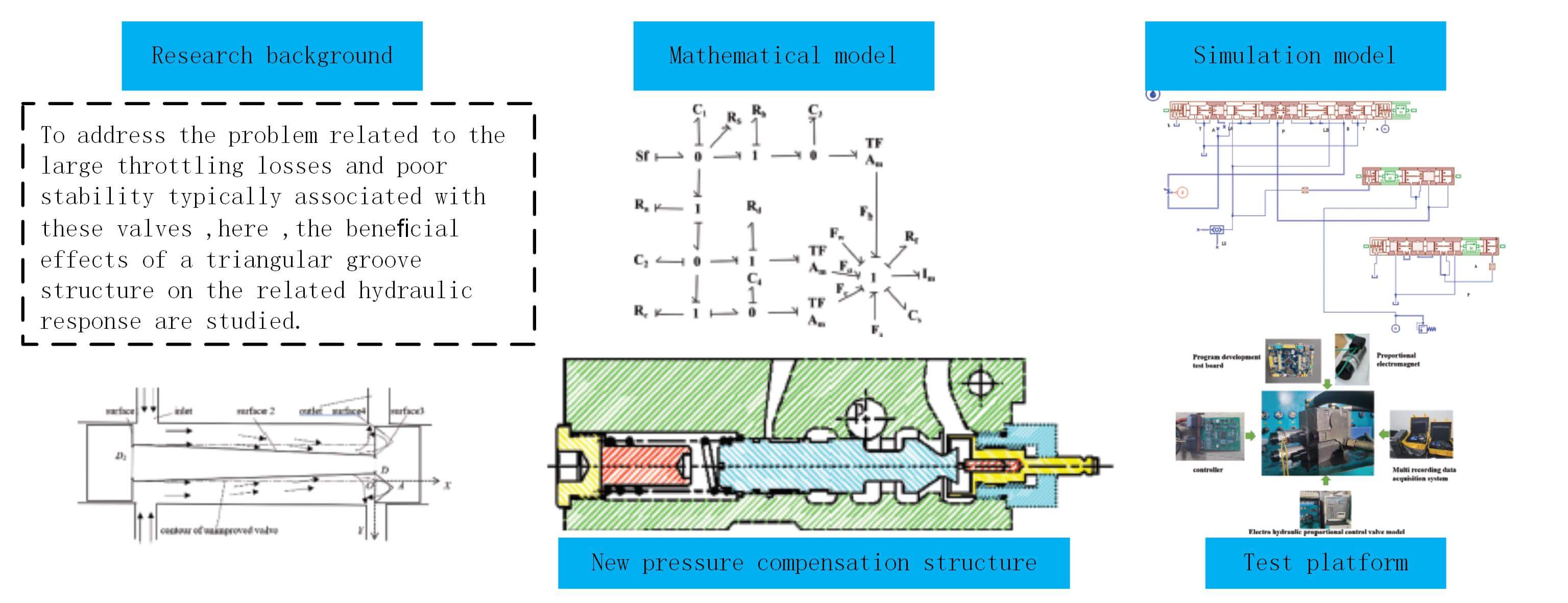
Electro-hydraulic proportional valve is the core control valve in many hydraulic systems used in agricultural and engineering machinery. To address the problem related to the large throttling losses and poor stability typically associated with these valves, here, the beneficial effects of a triangular groove structure on the related hydraulic response are studied. A mathematical model of the pressure compensation system based on the power-bond graph method is introduced, and the AMESim software is used to simulate its response. The results show that the triangular groove structure increases the jet angle and effectively compensates for the hydrodynamic force. The steady-state differential pressure at the valve port of the new pressure compensation structure was 0.65 MPa. Furthermore, experimental results show that the pressure difference at the main valve port is 0.73 MPa, and that the response time is less than 0.2 s. It is concluded that the new compensation structure has good pressure compensation response characteristics.Graphic Abstract
Keywords
Electrohydraulic proportional valve is the core control valve of hydraulic systems used in agricultural and engineering machinery. Its performance determines the reliability, stability, accuracy, and green energy savings of the entire hydraulic system. The performance of the electrohydraulic proportional valve directly affects the quality and efficiency of the entire operation [1–5]. The main drawback of electrohydraulic proportional valves is their poor pressure-compensation stability, which cannot meet the operational requirements of modern agricultural equipment in complex and dynamic field environments. This significantly hinders the development of high-end hydraulic components [6–10].
In recent years, electrohydraulic proportional valves and their pressure compensation technologies have rapidly developed. Rexroth and Eaton developed supporting technologies and products to satisfy various system requirements [11–15]. Some scholars have conducted in-depth research on pressure compensation valves to overcome traditional technical barriers. Xia et al. [16,17] analyzed the flow-pressure characteristics of a pressure compensation valve by considering the shape of the orifice as the research object. Milic et al. [18,19] analyzed the pressure compensation problem in an LUDV multiway valve and found that by reducing the spring stiffness of the pressure compensation valve, one can effectively increase the hydraulic buffer and improve the compensation effect. Grosbrink et al. [20,21] found that a system with pre-valve compensation has better speed regulation rigidity. They also studied the post-valve pressure compensation of a pressure compensation valve. However, these studies generally have insufficient innovation, and their structural design should be optimized. The pressure-compensation analyses focused on a certain parameter or variable, while the influence of other parameters and boundary conditions was not fully considered. The fretting response characteristics were poor and difficult to discern from the results. Moreover, there was a lack of objects for comparison, and it was impossible to define the technical level of the research results [22–26].
Therefore, in this study, an electrohydraulic proportional control valve was selected as the research object, and an advanced international reversing valve was selected as the reference object [27–31]. A mathematical model of the pressure compensation system was established using the power bond diagram method. The influence of the triangular groove shape of the valve core on the hydrodynamic response characteristics was analyzed using FLUENT. Simulation models of the pressure compensation system were built using AMESim software. A multiparameter simulation of the pressure compensation performance was conducted, and the parameters of the electrohydraulic proportional valve were optimized. Finally, the accuracy of the mathematical and simulation models of the pressure compensation system was verified experimentally.
2 Structural Composition and Working Principle of the Pressure Compensation System in the Electrohydraulic Proportional Valve
The pressure compensation system of an electrohydraulic proportional valve consists of a pressure compensation valve, spring, main valve, and various oil passages. The structure of the pressure compensation valve is illustrated in Fig. 1. The pressure compensation valve has a series-type pre-valve pressure compensation and is connected in series to the throttle port of the main valve to form a two-way speed-regulating valve. This ensures that the working pressure difference of the throttle valve does not change with load pressure fluctuation and realizes the independent function of the load. The pressure compensation valve has a separate modular interface design that can be directly inserted into the valve body without adjustment. The pressure compensation valve has the advantages of high-precision control, robust reliability, a reasonable and compact structure, and ease of maintenance.
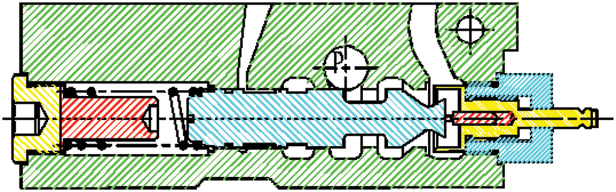
Figure 1: System structure of pressure compensation valve
The working principle of the pressure compensation system is that, when the valve is in operation, the hydraulic oil from the pressure port flows into the pressure compensation valve spool through the thin-walled hole to reach the installation valve seat. Subsequently, the spool is pushed to the left toward the position where the thin-walled hole is closed. The pressure compensation valve port and thin-walled hole opens, and a portion of the hydraulic oil input from the pressure port flows into the main valve cavity. Thus, the load pressure and main valve orifice exhibit a logical relationship. The remaining hydraulic oil flows through the thin-walled hole into the pressure cavity formed by the right end of the pressure compensation valve spool and the installed valve seat and participates in the stress of the pressure compensation valve spool. After a certain period, the pressure-compensating valve spool reaches a balanced state.
3 Mathematical Model and Characteristic Analysis of Pressure Compensation System
3.1 Mathematical Model of the Pressure Compensation System Based on Power-Bond Diagram
Fig. 2 shows the power-bond model of the pressure compensation system based on the working principle of the pressure compensation valve.
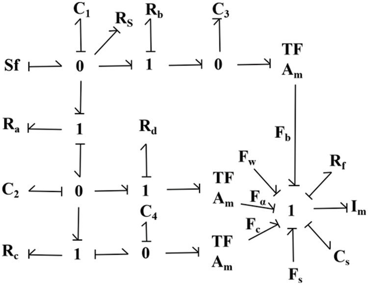
Figure 2: Power-bond diagram of the new pressure compensation system
A mathematical model is derived from the aforementioned power-bond diagram. The generalized displacement of element C and generalized momentum of element I in this system are considered as the state variables, which were set as Xi (i = 1, 2, 3, 4, 5, 6), expressed as follows:
which is
According to the above expressions, the state equation can be deduced as follows:
Each parameter in the formula is defined as follows:
Sf——Input source,
3.2 Theoretical Calculation of the Main Parameters of the Pressure Compensation System
(1) Calculation of the pressure compensation valve port liquid resistance.
The valve port of the pressure compensation valve is similar to the nonlinear liquid resistance and is expressed as follows:
In the formula
(2) Calculation of the liquid guide during the process, from the small hole on the left side to the installed valve seat through the valve spool interior.
During this process, oil passes through thin-walled holes 1, 2, and 3. The liquid guide of the thin-walled holes is given as follows:
The following can be determined using the orifice flow formula:
Each parameter in the formula is defined follows:
Via calculation, it is known that
Each parameter in the formula is defined as follows:
(3) Calculation of the liquid guide during the process, from the small hole on the right side to the installed valve seat through the valve spool interior.
Similar to (2), the liquid guide can be expressed as:
Each parameter in the formula is defined as follows:
(4) Calculation of fluid power on the pressure compensation valve spool.
The steady-state flow force can be expressed using the valve port flow and flow rate formulas as follows:
Each parameter in the formula is defined as follows:
The pressure compensation valve orifice was of the triangular groove type. The two orifices are arranged symmetrically; therefore, the flow area is:
Therefore,
Each parameter in the formula is defined as follows:
4 Simulation Results and Analysis
4.1 Simulation of Hydrodynamic Change in the Valve Core
An improved valve core structure was designed, as shown in Fig. 3. The valve stem was shaped like a round table by reducing the diameter on one side. A triangular groove was circumscribed on each step on the same side. After part of the liquid flow is guided through the triangular groove, the flow direction changes; that is, a flow component along the closing direction of the valve core is generated. This part of the liquid flow impacts the positive direction liquid flow, such that the flow angle of the liquid at the outlet increases; therefore, the jet angle increases and the hydrodynamic force decreases. As the diameter of one side of the valve stem decreases, the space on the side of the valve stem increases, enabling more liquid to be guided through the triangular groove, further reducing the hydraulic force.
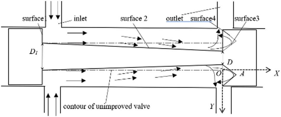
Figure 3: Improved valve core structure
Fig. 4 shows the jet angle distribution at the outlet of the original valve core. Fig. 5 shows the change in the jet angle when the bottom radius of the fixed triangular groove remains unchanged and the bottom depth increases. The comparison shows that the improved structure effectively increases the jet angle at the outlet, which increases with the groove bottom depth.
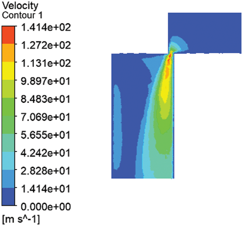
Figure 4: Original spool jet angle

Figure 5: Jet angle with increasing groove bottom depth
Fig. 6 shows the change in the jet angle when the fixed groove bottom depth is unchanged and the groove bottom radius increases. The comparison shows that the jet angle increases with an increase in the groove bottom radius; however, the change range of the jet angle is small.

Figure 6: Jet angle with increasing groove bottom radius
The simulation results showed that the triangular groove structure can produce a flow component in the negative direction. This part of the liquid impacts the liquid flow in the positive direction, such that the flow angle of the liquid flow at the outlet increases; that is, the jet angle increases. The structure effectively compensates for the hydrodynamic force.
4.2 Simulation of the New Pressure Compensation System
The simulation model of the pressure compensation system in the electrohydraulic proportional control valve of agricultural and engineering machinery is shown in Fig. 7. To compare the simulation results of the advanced reversing valve and optimize the design of the electrohydraulic proportional control valve parameters, the influences of the spring preload, spring stiffness, and pressure compensation valve viscous damping coefficient on the pressure-compensation characteristics were studied.

Figure 7: A simulation model of the new pressure compensation system
The simulation parameters of the model are set as shown in Table 1.

(1) Influence of spring stiffness on compensation characteristics.
The spring stiffness comparison values were 20,000, 25,000, and 30,000 N/m. The simulation duration was set to 0.2 s. Fig. 8 shows the response curves for the different spring stiffness values.
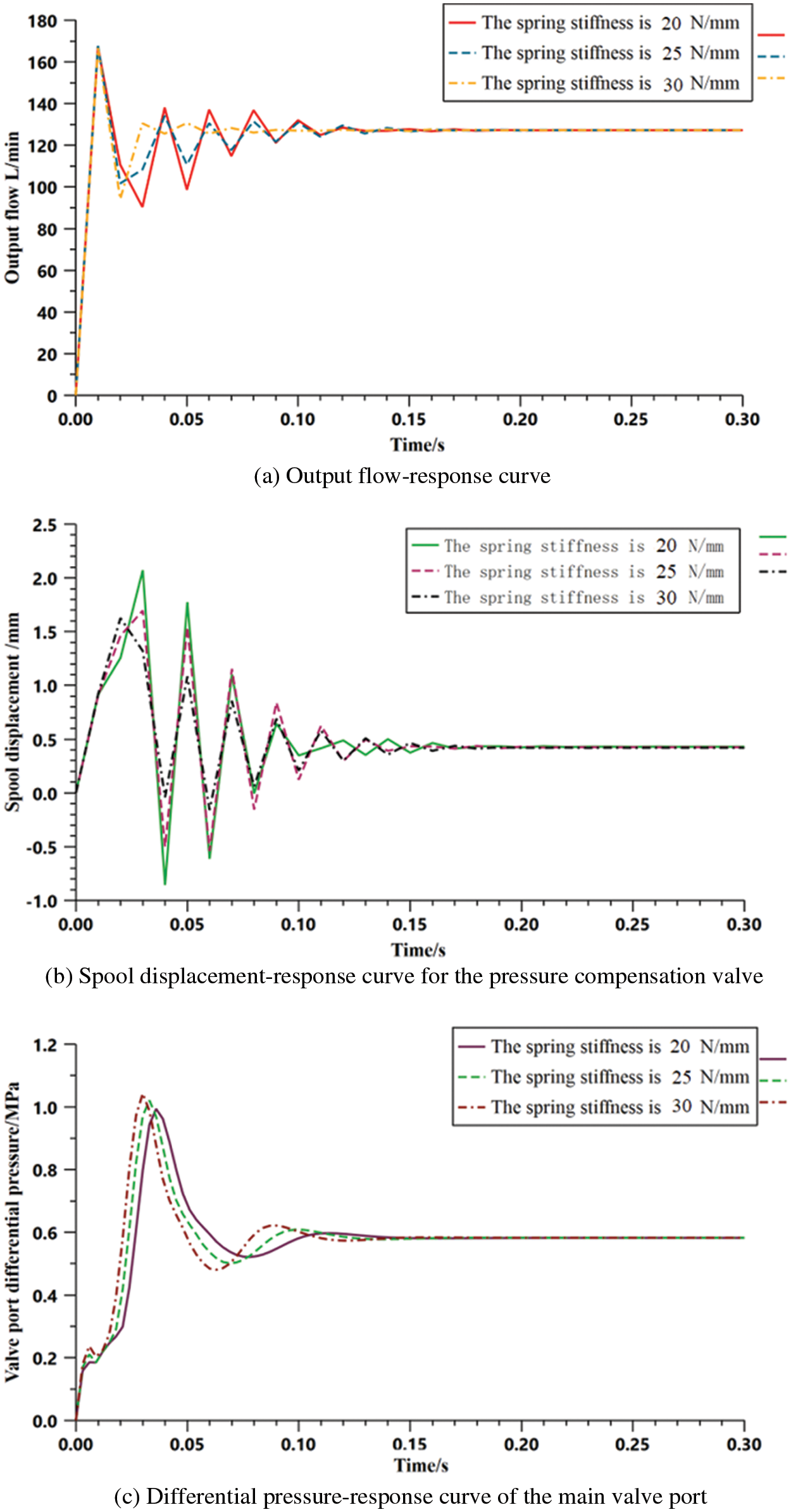
Figure 8: Response curves for different spring stiffness values
From Fig. 8, it can be seen that as spring stiffness increases, the response speed of the output flow and differential pressure increases, peak time and peak value significantly decrease, system-adjustment time increases, stability decreases, and the steady-state output value slightly increases. For the displacement response of the pressure compensation valve spool, the peak value decreased as the spring stiffness increased; however, the maximum overshoot increased. When the spring stiffness was 30,000 N/m, the system adjustment time was shortest.
The spring preload affects the dynamic response and steady-state characteristics of the pressure compensation system of an electrohydraulic proportional valve. Within a certain range, the performance of the pressure compensation system can be improved by increasing spring stiffness. For the existing pressure compensation system model, the spring stiffness was set to 30,000 N/m.
(2) Influence of the spring preload on the compensation characteristics.
The comparison values of the spring preloads were 456, 471, and 486 N. The simulation duration was set as 0.2 s. The simulation results are shown in Fig. 9.

Figure 9: Response curves for different spring preloads
Fig. 9 shows that the impact of the spring preload on the dynamic response and steady-state characteristics of the pressure compensation system of the electrohydraulic proportional valve. With the increase in spring preload of the pressure compensation valve, the maximum overshoot of the output flow and differential pressure significantly decreased, and the response stability slightly improved and the time to reach a steady-state decreased accordingly. The best response of the spool displacement was obtained at a spring preload of 471 N. When the preload was 486 N, the greatest fluctuation in spool displacement and longest system adjustment time were observed.
With the other parameters of the system remaining constant, increasing the spring preload of the pressure compensation valve within a certain range improves the stability of the pressure difference of the pressure compensation system, and the response characteristics of the output flow. It also improves the electrohydraulic pressure-compensation characteristic index of the proportional valve. For the current pressure compensation system model, a spring preload of 471 N is ideal.
(3) Influence of viscous friction coefficient on compensation characteristics.
The viscous friction coefficients in the dynamic simulation model were set as 0.5, 1.5, and 2.5 s⋅N⁄m, while other system parameters remained unchanged. The system pressure, load pressure, and simulation duration were 30, 29, and 0.2 s, respectively. The response curves for different viscous friction coefficients were obtained and are presented in Fig. 10.
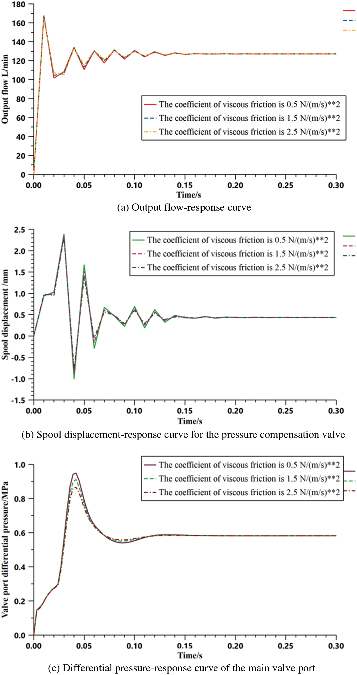
Figure 10: Response curves for different viscous friction coefficients
Fig. 10 shows that the change laws of the output flow-response curve and main valve port differential-pressure response curve are approximately the same. With the increase in the viscous friction coefficient, the peak value of the curve significantly increased, the peak time was slightly delayed, the maximum overshoot increased, and the system stability deteriorated. The time to reach a stable output state was the shortest at a viscous friction coefficient of
The magnitude of the viscous friction coefficient is a key factor affecting the dynamic response and steady-state characteristics of the pressure compensation system of the electrohydraulic proportional valve. Within a certain range, increasing or decreasing the viscous friction coefficient improved the performance of the pressure compensation system. Thus, in the design and manufacturing process, designers should pay special attention to the indirect control of the viscous friction coefficient. In the existing pressure compensation system model, the viscous friction coefficient was set to 2.5 s⋅N/m.
An electrohydraulic proportional-valve hydraulic system test platform was built to verify the accuracy of the mathematical model and simulation results of the pressure compensation system of the electrohydraulic proportional valve, as shown in Fig. 11. The test platform consisted of a measured electrohydraulic proportional valve, proportional electromagnet, load proportional relief valve, electrohydraulic proportional controller, and data acquisition system.
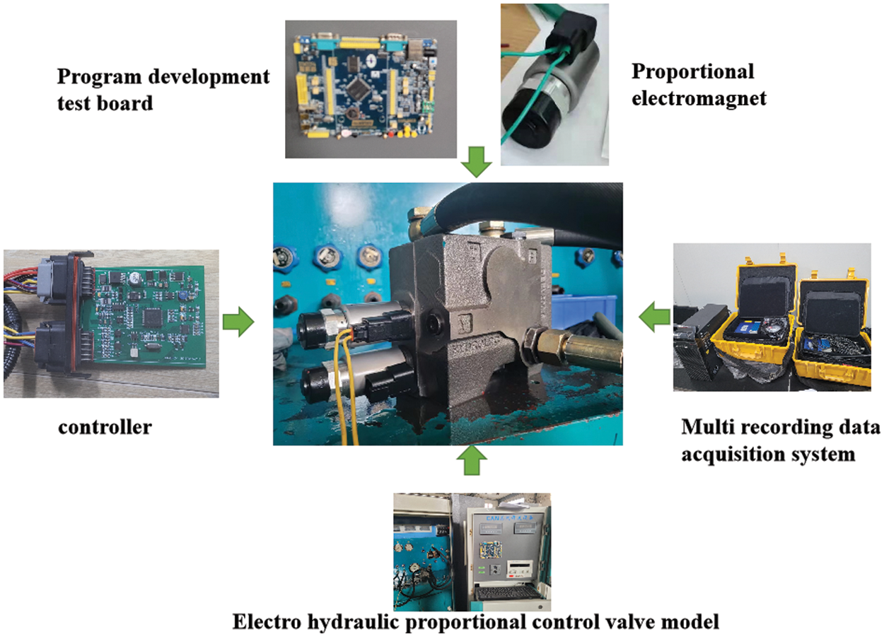
Figure 11: Electrohydraulic proportional valve hydraulic system test platform
The system pressure was set to 30 MPa, and the loading pressure of the load-proportional relief valve was set to 29 MPa. A step signal with an amplitude of 8 V is applied to the proportional controller. The output flow response, spool displacement response, and main valve port differential pressure-response curves were obtained experimentally, as shown in Fig. 12.
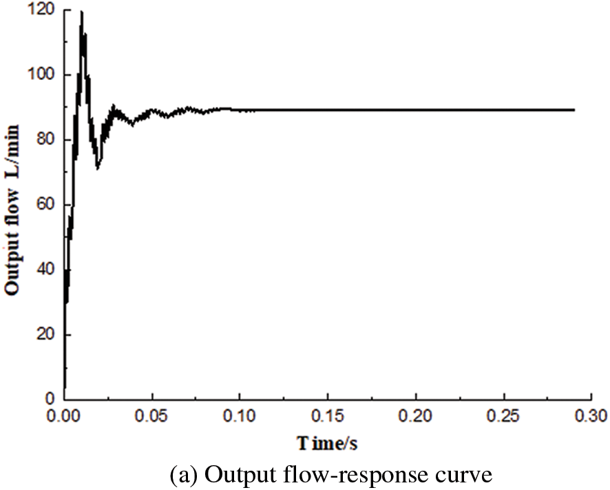

Figure 12: System response curves under step signal
As shown in Fig. 12, the steady-state value of the output flow was 89.1 L⁄min, the maximum overshoot was approximately 33.3%, and the adjustment time was 0.12 s. The displacement-response time of the pressure compensation valve spool was 0.15 s, and the steady-state value was −0.49 mm. The response time of the pressure difference at the valve port was 0.2 s. The steady-state pressure difference was 0.73 MPa. When the main valve spool was at rest, the pressure difference between the two ends was 0.65 MPa. When the main valve port was open, the differential pressure changed dynamically with the response of the system pressure, causing output flow fluctuations. Thus, the trends in the changes shown in Figs. 12a and 12c are the same.
A comparison of the response curves of the test and simulation show that the simulation model built in this study accurately simulates the dynamic characteristics of the actual pressure compensation system.
(1) The influence of the triangular groove shape of the valve core on the hydrodynamic response characteristics was analyzed using FLUENT software. The results showed that the triangular groove structure could produce a flow component in the negative direction. This part of the liquid flow reversely impacts the liquid flowing in the positive direction, thereby increasing the flow angle of the liquid at the outlet and jet angle. This structure effectively compensated for the hydrodynamic force and reduced pressure loss along the path.
(2) The simulation models of the pressure compensation systems were built using AMESIM software. The influence of the pressure compensation valve spring preload, spring stiffness, and viscous damping coefficient on the pressure compensation characteristics was studied. The final spring preload, spring rate, and viscous damping coefficient were 471 N, 30000 N/m, and 2.5 s⋅N/m, respectively. A comparison of the load-step changes for the two systems showed that the response times of both systems were similar. The maximum fluctuations of the new pressure compensation system were 0.54 L/min, 0.017, and 0.006 MPa, with improved stability. In other words, its pressure compensation characteristics were better than those of the reverse valve.
(3) A test platform was built to evaluate the electrohydraulic proportional valve. The results showed that the pressure difference at the main valve port was approximately 0.73 MPa, and the response time was approximately 0.2 s. The test and simulation curves were consistent, which verifies the accuracy of the mathematical and simulation models. An experimental analysis of different working conditions proved that the electrohydraulic proportional valve has good pressure-compensation performance and can replace similar products.
Acknowledgement: I would like to thank my tutor, R.L., for his support and guidance. I would also like to express my gratitude to my coworkers for their support and understanding, without which I would have never completed my research. I would also like to especially thank my family and friends, who listened to my frustrations and believed in me, sometimes more than I believed in myself.
Funding Statement: This research was funded by the 2020 Shandong Province Key Research and Development Programs (Major Technological Innovation Projects): Construction Machinery Integration Research and Application of Key Technologies for Intelligent Integration and Matching of Vehicle Assembly (2020CXGC011005), Large Tractor Hydraulic CVT Intelligent Continuously Variable Transmission Integration Research and Application (2020CXGC010806), and Development and Application of High-Horsepower High-Efficiency Intelligent Tractors (2021CXGC010812).
Conflicts of Interest: The authors declare that they have no conflicts of interest to report regarding the present study.
References
1. Liu, K., Gao, Y., Tu, Z. (2016). Energy saving potential of load sensing system with hydro-mechanical pressure compensation and independent metering. International Journal of Fluid Power, 17(3), 173–186. https://doi.org/10.1080/14399776.2016.1185877 [Google Scholar] [CrossRef]
2. Casoli, P., Riccò, L., Campanini, F., Lettini, A., Dolcin, C. (2015). Mathematical model of a hydraulic excavator for fuel consumption predictions. Fluid Power Systems Technology, 57236, V001T01A035. https://doi.org/10.1115/FPMC2015-9566 [Google Scholar] [CrossRef]
3. Pawananont, K., Leephakpreeda, T. (2019). Sequential control of multichannel on–off valves for linear flow characteristics via averaging pulse width modulation without flow meter: An application for pneumatic valves. Journal of Dynamic Systems, Measurement, and Control, 141(1), 011007. https://doi.org/10.1115/1.4040969 [Google Scholar] [CrossRef]
4. Bhushan, B. M., Yoon, J. Y., Griffith, L. G., Trumper, D. L. (2020). Flux-biased, energy-efficient electromagnetic micropumps utilizing bistable magnetic latching and energy-storage springs. IEEE/ASME Transactions on Mechatronics, 26(5), 2362–2372. https://doi.org/10.1109/TMECH.2020.3038885 [Google Scholar] [CrossRef]
5. Hsieh, C. T., Lai, C. P. (2019). Nonlinear dynamic analysis and control of a hydraulic press electro-hydraulic servo system. Journal of Low Frequency Noise Vibration and Active Control, 38(3), 1594–1606. https://doi.org/10.1177/1461348418813021 [Google Scholar] [CrossRef]
6. Dindorf, R., Wos, P. (2019). Force and position control of the integrated electro-hydraulic servo-drive. 2019 20th International Carpathian Control Conference (ICCC), pp. 277–282. Poland. [Google Scholar]
7. Kumar, S., Tewari, V. K., Bharti, C. K., Ranjan, A. (2021). Modeling, simulation and experimental validation of flow rate of electro-hydraulic hitch control valve of agricultural tractor. Flow Measurement and Instrumentation, 82, 102070. https://doi.org/10.1016/j.flowmeasinst.2021.102070 [Google Scholar] [CrossRef]
8. Essa, M. E. S. M., Aboelela, M. A., Hassan, M. M., Abdraboo, S. M. (2019). Fractional order fuzzy logic position and force control of experimental electro-hydraulic servo system. 2019 8th International Conference on Modern Circuits and Systems Technologies (MOCASTpp. 1–4. Thessaloniki, Greece. [Google Scholar]
9. Ko, Y. R., Kim, T. H. (2020). Feedforward plus feedback control of an electro-hydraulic valve system using a proportional control valve. Actuators, 9(2), 45. https://doi.org/10.3390/act9020045 [Google Scholar] [CrossRef]
10. Tic, V., Rotovnik, A., Lovrec, D. (2021). Impact of proportional valves’ differences to ensure uniform motion of hydraulic motors. International Journal of Simulation Modelling, 20(1), 52–63. https://doi.org/10.2507/IJSIMM [Google Scholar] [CrossRef]
11. Wos, P., Dindorf, R. (2019). Self-tuning controllers based on polynomial methods for electro-hydraulic servo drive. 10th International Conference on Applied Mechanics, vol. 2077, pp. 020063. Poland. [Google Scholar]
12. Thomas, A. T., Parameshwaran, R., Sathiyavathi, S., Starbino, A. V. (2021). Practical profile tracking for a hydraulic press using sliding mode controller. Proceedings of the Institution of Mechanical Engineers Part C: Journal of Mechanical Engineering Science, 236(2), 1202–1213. [Google Scholar]
13. Hagen, D., Padovani, D., Choux, M. (2020). A comparison study of a novel self-contained electro-hydraulic cylinder versus a conventional valve-controlled actuator–Part 1: Motion control. Actuators, 8(4), 79. https://doi.org/10.3390/act8040079 [Google Scholar] [CrossRef]
14. Thangavel, S., Maheswari, C., Priyanka, E. B., Iyanka, E. B. (2021). Dynamic modeling and control analysis of industrial electromechanical servo positioning system using machine learning technique. Journal of Testing and Evaluation, 49(4), 2425–2440. https://doi.org/10.1520/JTE20200159 [Google Scholar] [CrossRef]
15. Lisowski, E., Filo, G. (2017). Analysis of a proportional control valve flow coefficient with the usage of a CFD method. Flow Measurement and Instrumentation, 53(B), 269–278. https://doi.org/10.1016/j.flowmeasinst.2016.12.009 [Google Scholar] [CrossRef]
16. Xia, Q. C. (2013). Research on static and dynamic characteristics of a series of load-sensitive proportional multi-way valve (Master Thesis). Yanshan University, China. [Google Scholar]
17. Zhao, R. H., Liao, Y. Y., Lian, Z. S., Li, R. Z., Guo, Y. C. (2021). Research on the performance of a novel electro-hydraulic proportional directional valve with position-feedback groove. Proceedings of the Institution of Mechanical Engineers, Part E: Journal of Process Mechanical Engineering, 235(6), 1930–1944. https://doi.org/10.1177/09544089211024424 [Google Scholar] [CrossRef]
18. Milic, V., Situm, Z., Essert, M. (2010). Robust H-infinity position control synthesis of an electro-hydraulic servo system. ISA Transactions, 38(3), 1594–1606. [Google Scholar]
19. Yi, Y., Hu, Y. P., Mo, H. (2018). Research on steady characteristics of F-π bridge lectrohydraulic proportional pressure reducing valve. International Journal of Fluid Machinery and Systems. 11(2), 154–162. [Google Scholar]
20. Grosbrink, B., Harms, H. (2009). Control concept for an advanced load-sensing system. Proceedings of the 7th International Conference on Fluid Power Transmission and Control, Hangzhou, China. [Google Scholar]
21. Axin, M., Eriksson, B., Palmberg, J. O., Krus, P. (2011). Dynamic analysis of single pump, flow controlled mobile systems. The Twelfth Scandinavian International Conference on Fluid Power, pp. 223–238. Tampere, Finland. [Google Scholar]
22. Axin, M., Eriksson, B., Palmberg, J. O. (2009). Energy efficient load adapting system without load sensing: Design and evaluation. The 11th Scandinavian International Conference on Fluid Power, pp. 58–73. Linkoping, Sweden. [Google Scholar]
23. Wu, W., Wei, C. H., Zhou, J. J., Hu, J. B., Yuan, S. H. (2021). Numerical and experimental nonlinear dynamics of a proportional pressure-regulating valve. Nonlinear Dynamics, 103(2), 1415–1425. https://doi.org/10.1007/s11071-020-06125-0 [Google Scholar] [CrossRef]
24. Mannesmann, R. (2019). Mobile hydraulics and electronics. RE6400/08.92. [Google Scholar]
25. Zhao, J. W. (2013). Research on shunt control of multi-actuator load sensing system (Master Thesis). Yanshan University, China. [Google Scholar]
26. Wang, B. L. (2009). Application of load sensing and pressure compensation technology in aerial hydraulic system. China Ship Repair, 22(4), 61–62. [Google Scholar]
27. Sun, H. L., Li, R. C., Xu, J. K., Xu, F. N., Zhang, B. et al. (2021). Fractional modeling and characteristic analysis of hydro-pneumatic suspension for construction vehicles. Processes, 9(8), 1414. https://doi.org/10.3390/pr9081414 [Google Scholar] [CrossRef]
28. Sun, H. L., Li, R. C., Huang, M. M., Li, Z., Xu, J. K. (2021). Numerical simulations of the influence of inert gases (N2/CO2) on combustion characteristics of laminar-premixed biosyngas flame. ACS Omega, 2(6), 14585–14597. https://doi.org/10.1021/acsomega.1c01729 [Google Scholar] [PubMed] [CrossRef]
29. Xu, J. K., Li, R. C., Li, Y. C., Zhang, Y. S., Sun, H. L. et al. (2021). Research on variable-universe fuzzy control technology of an electro-hydraulic hitch system. Processes, 9(11), 1920. https://doi.org/10.3390/pr9111920 [Google Scholar] [CrossRef]
30. Li, R. C., Ding, X. K., Lin, J. H., Chi, F., Xu, J. K. et al. (2021). Study on the influence of triangular groove structure on steady-state flow force compensation characteristics. Applied Sciences, 11(23), 11354. https://doi.org/10.3390/app112311354 [Google Scholar] [CrossRef]
31. Al-Zughaibi, A., Xue, Y. Q., Grosvenor, R., Okon, A. (2019). Design and investigation of pole assignment controller for driving nonlinear electro hydraulic actuator with new active suspension system model. Proceedings of the Institution of Mechanical Engineers, Part D: Journal of Automobile Engineering, 233(13), 3460–3479. [Google Scholar]
Cite This Article
 Copyright © 2023 The Author(s). Published by Tech Science Press.
This work is licensed under a Creative Commons Attribution 4.0 International License , which permits unrestricted use, distribution, and reproduction in any medium, provided the original work is properly cited.
 Downloads
 Citation Tools