
 Submit a Paper
 Propose a Special lssue
 Open Access
ARTICLE

Improved Design of a Hydraulically Expanded Overhead Cylinder for an Automotive Torsion Beam
1 Anhui Polytechnic University, Wuhu, 241000, China
2 Chinese University of Hong Kong (Shenzhen), Shenzhen, 518172, China
* Corresponding Author: Kefan Yang. Email:
(This article belongs to the Special Issue: Computational Mechanics and Fluid Dynamics in Intelligent Manufacturing and Material Processing)
Fluid Dynamics & Materials Processing 2023, 19(5), 1317-1338. https://doi.org/10.32604/fdmp.2023.024265
Received 27 May 2022; Accepted 09 August 2022; Issue published 30 November 2022
 View Full Text
 Download PDF
Abstract
The design of hydro-bulge molds, able to provide hollow parts with special-shaped cross-sections, is still a pretty complicated task (especially for what concerns the design of the related hydraulic system and its “synchronization”). In the present work, this task is addressed through the introduction of a new type of overhead cylinder hydraulic synchronization system, able to correct automatically any deviation from the optimal process. Using the AMESim software, the displacement synchronization curve of the piston rods of the two cylinders is obtained and it is verified that the system is able to implement an automatic deviation correction function by adjusting the bidirectional servo valve. A mathematical model for the synchronization system is presented, and the transfer function of the closed-loop control system is determined accordingly. The results show that the system response is generated at about 0.1∼0.2 s with the system reaching an equilibrium state at about 0.2 s.Keywords
Nowadays, the degree of hydraulic transmission has become one of the critical signs to measure the industrial level of businesses and nations alike. In developed countries, 95% of factory machinery, 90% of CNC machining centers, and more than 95% of automated production lines have adopted hydraulic transmission technology [1]. Hydraulic technology has essential application value and development potential in machinery manufacturing and other industries. We can only meet the needs of the machinery manufacturing industry by constantly studying and improving the demand for hydraulic technology. Hydraulic simulation technology is critical in the design, analysis, and optimization of hydraulic systems and is gradually attracting the industry’s attention [2].
Kumar et al. [3] studied the influence of the attenuation characteristics of the hydraulic accumulators on the response of the hydrostatic drive system of mining vehicles and simulated it in MATLAB/Simulink. The simulated test results were obtained according to the hydraulic motor speed and system pressure under different resistive loads and accumulator capacity and verified with the experimental test data. By using the validated model, the velocity response of the hydrostatic actuator under different accumulator precharge pressures and inertial loads on the motor shaft is also studied. Yahya et al. [4] established the positive and negative displacement simulation model of valveless electro-hydraulic servo system to solve the problems of slow response speed and poor displacement tracking accuracy of hydraulic transmission technology and model the hydraulic simulation and motor by using AMESim and Simulink software. The system is simulated separately. To improve the performance of a valveless electro-hydraulic servo system, a fuzzy PID controller is introduced and simulated by adding a fuzzy PID controller. Mishra et al. [5] emphasized the design and implementation of a nonlinear offline feedforward controller related to PID controller as a fault-tolerant control measure for the closed-loop hydraulic system. The results show that the control model achieves good consistency between the requirements of various load conditions (such as step load, sine load, variable load, triangle load, etc.) and the real-time speed response. Feng et al. [6] proposed the method of using ultra-high pressure hydraulic system to simplify the tablet press structure, designed the laboratory ultra-high pressure tablet press for XRF spectral analysis sample manufacturing, used AMESim software to simulate the established hydraulic system model, and reasonably set the relevant parameters of the simulation model based on theoretical analysis and relevant experience. The AMESim simulation results are obtained, and each hydraulic circuit system’s motion and flow characteristics are analyzed, which verifies the rationality of the hydraulic system. Yu et al. [7] established a mathematical model of pressure pulsation of the pile hammer hydraulic system and analyzed the pressure pulsation results using AMESim. It is proved that only the accumulator with optimal pressure and capacity can effectively absorb pressure pulsation and ensure the efficiency of the pile hammer hydraulic system. Shen et al. [8] studied the control problem of a class of hydraulic servo systems with digital communication constraints and model uncertainties. They proposed a collaborative design method of adaptive robust sliding mode controller with event triggering strategy and finite-time disturbance observer. In this paper, the mathematical modeling of the control system is completed, and the step response curve of the system is successfully obtained in Simulink, which verifies the control characteristics of the synchronous control system of the overhead cylinder. The control system has good performance and meets the design requirements.
Bao et al. [9] aimed at the problems of high nonlinear, weak stiffness, and slow response speed of common PID control of frequency conversion hydraulic system of irrigation machine, and adopt fuzzy adaptive control strategy to improve system performance. Based on the co-simulation of AMESim and MATLAB, a fuzzy controller is designed, and expert experience is combined with a PID controller. The controller can adjust the parameters automatically according to the changes in system working conditions to improve the system’s dynamic characteristics. According to the coupling characteristics of hydraulic rock drill propulsion system and impact system, Liu et al. [10] derived the calculation formula of the optimal axial thrust of hydraulic rock drill propulsion system, constructed a hydraulic rock drill composite drive propulsion system based on electro-hydraulic proportional pressure reducing valve and high-speed on-off valve, and established its dynamic model. Finally, taking the optimal axial thrust as the goal, the fuzzy PID control strategy is adopted to realize the online and intelligent control of the axial thrust of the hydraulic rock drill propulsion system. Nguyen et al. [11] analyzed and simulated the dynamics model of the hydraulic system that drives the mechanical operating equipment and obtained A hydraulic system that meets the requirements of fast response and high accuracy. Given the low efficiency of the traditional hydraulic system, Kittisares et al. [12] proposed an alternating pressure control system based on an alternating pressure source system. They verified the controlled accuracy of position and pressure of the scenario through simulation experiments. In this paper, the modeling and simulation of the hydraulic system are completed in AMESim, and the synchronization curves of the displacement of the piston rod of two cylinders are obtained under two working conditions, which verifies that the hydraulic system can realize the automatic deviation correction function.
In the present study, the product structure of the automotive torsion beam is designed, and the processing process of parts is preliminarily determined. The hydraulic expansion mold structure of the automotive torsion beam was intended. According to the actual processing conditions and the synchronization requirements of hydraulic cylinders on both sides, a new synchronous system of the overhead cylinder that can automatically correct deviation was designed. The motion parameters of the overhead cylinders on both sides during the processing of the torsion beam were determined, and the hydraulic system parts were selected. Modeling and simulation are completed in AMESim, and the synchronous characteristic curves of piston rod displacement of two cylinders are obtained under two working conditions. When the load pressure of two hydraulic overhead cylinders is the same, the movement of the two cylinders’ piston rod is synchronous, and the displacement error is 0 mm. When the load pressure of the two hydraulic overhead cylinders is different, the following valve can adjust the throttle area of the valve outlet of the two cylinders according to the displacement of the spool, which verifies the automatic correction function of the hydraulic system. The mathematical modeling of the synchronization system is completed, and the step response curve of the system with good performance is successfully obtained in Simulink; the results show that the response action of the system is generated at about 0.1∼0.2 s and the system reaches the equilibrium state at about 0.2 s, which verifies the response characteristics of the system, and completes the characteristic analysis of the synchronization system of the overhead cylinder of the hydraulic expansion mold of the torsion beam.
2 Design of Torsion Beam Structure and Bulging Process Route
2.1 Design and Analysis of Automobile Torsion Beam Structure
CATIA is used to carry out three-dimensional modeling design for the closed tubular torsion beam. Basic dimensions are as follows: the length is 1260 mm, the maximum height difference between two-part ends is 85.2 mm, the surface area is 0.356
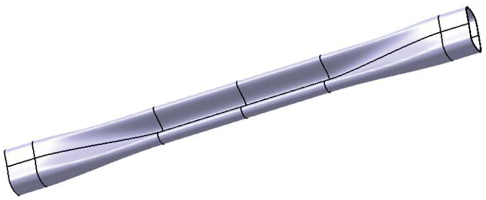
Figure 1: Original digital model drawing of torsion beam parts
Because the parts will be extended to a certain extent in the process of swelling, and the length of the billet is related to the size of the elements, and in the process of swelling, the filler device will be set for the billet, to improve the utilization rate of the material as much as possible, the length of the pipe fittings used for the beam is preliminarily determined to be 1290 mm. Therefore, the blank tube size is defined as
2.2 Main Technical Parameters of Bulging Hydraulic Process of Torsion Beam
Initial yield pressure is the internal pressure required at the beginning of the plastic deformation of the pipe [14]. As shown in Eq. (1), assuming that the tube is a cylindrical shell bearing internal pressure, and without considering the work hardening of pipe fittings, combined with the Tresca yield criterion, the yield pressure of hydraulic expansion of pipe fittings is:
where:
where
In the later stage of hydraulic bulging, the parts have basically been attached to the mold, while more forming pressure is needed to shape the fillet area to ensure dimensional accuracy. The force of the fillet increases with the decrease of the fillet radius, and there is no axial feeding in the fillet stage. As shown in Eq. (2), the formula for calculating integral pressure is summarized as follows:
where:
where
In the process of hydraulic bulging, the internal pressure of pipe fittings will act indirectly on the mold. The clamping force is needed to make the mold close without gaps in the forming process. If this force is too large, it will cause damage to the die. The calculation of the clamping force is mainly to determine the capacity of the hydraulic clamping press, as shown in Eq. (3). The calculation formula is:
where:
where
The torsion beam manufactured by hydraulic bulging technology can be supplemented by axial feeding during the bulging process, which can reduce the thinning trend of the wall thickness of the forming area and make the wall even and with a better forming effect. In the ideal state, the amount of feeding is the one in that the selected tube billet is completely formed into expansion parts, and the surface area of the pipe fittings does not change before and after forming. However, in actual production, due to the friction between the tube blank and the mold and the structural characteristics of torsion beam parts, the filling material at both ends cannot flow entirely to the middle forming area, as shown in Eq. (4). In general, the actual feeding amount is 60%∼80% of the ideal feeding amount [16].
where:
where
3 Design of Bulging Hydraulic Die and Hydraulic Synchronization System
3.1 Design of the Overall Scheme of Hydraulic Bulging Die
The bulging hydraulic mold comprises an upper die and lower die bases, punch, matrix, left and right axial sealing plugs, positioning plates, guide columns and guide sleeves. Fig. 2 shows the schematic diagram of the final assembly of the hydraulic expansion mold. To avoid leakage and other hydraulic system problems, combined with the design standard of bulging hydraulic die, a whole mold was designed. This plan has three points:
(1) The whole mold comprises the upper and lower two mold bases and the inner mold. The internal punch and matrix die adopt a mosaic structure, which is embedded in the groove of the upper and lower die seat by screws and positioned by the positioning pin. The hydraulic cylinders on both sides are fixed on the sliding platform of the lower die seat. The piston rod stroke of the hydraulic cylinder is controlled by a displacement sensor in the control system to control its axial feed. The overall size of the mold is defined as
(2) The upper die moves downward, and the limit plate on both sides of the lower die seat controls the closing clearance of the die through the positioning of the guide pillar guide sleeve of the four angles of the lower mold seat and the guide block on both sides when the mold is closed. When the mold is closed, the high-pressure liquid is injected and pressurized inwards through the holes connecting the plug and the piston rod on both sides. Meanwhile, the piston rod on both sides pushes the sealing plug inward to feed the filling material;
(3) After expansion, two symmetrical cylinders are fixed in the torsion beam parts’ symmetry groove of the lower die seat. The top plate is fixed on the front end of the cylinder rod. The top plate acts on the concave die insert block to push out the parts, which are reset after removal.
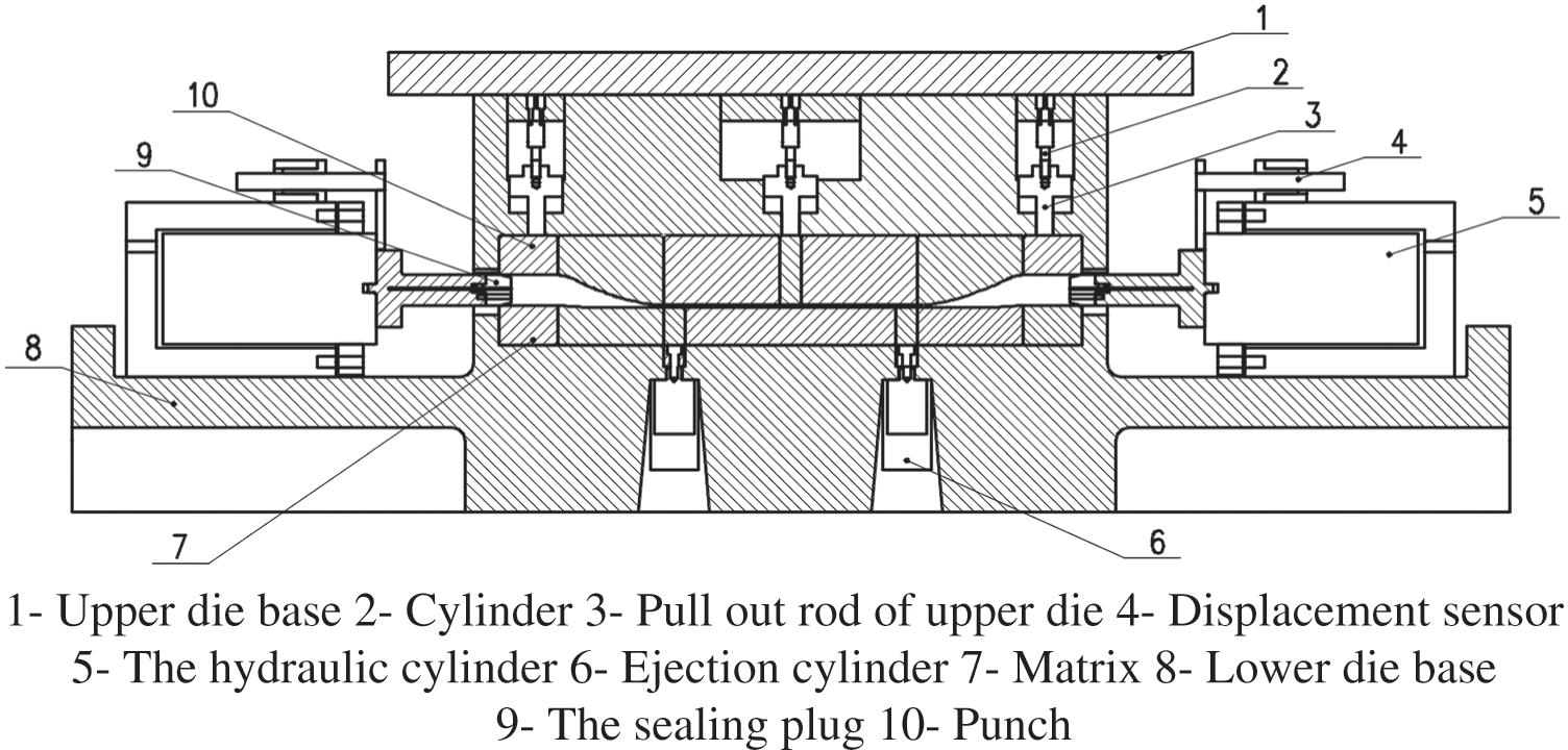
Figure 2: General assembly diagram of hydraulic expansion die for torsion beam
According to the shape of the two ends of the torsion beam, the plug is designed as a tapered table, the front end of the plug is 15 mm long into the billet part, the middle part is 40 mm long in direct contact with the mold, and the junction of the two parts is the contact sealing part between the plug and the end of the billet. As shown in Fig. 3, water is injected into the piston rod’s injection holes on both sides during hydraulic expansion. The water flows into the mold for pressurization from the four outlet holes of the plug through the internal flow channel. In this paper, the front end of the plug is directly contacted with the end of the tubing, and the small deformation of the joint is caused by the squeezing of the axial feeding force of the hydraulic cylinders on both sides to achieve a seal. Compared to soft seals, this form of a hard seal with direct metal-to-metal contact is suitable for high-pressure environments. It has the advantage of good wear resistance and mechanical properties.
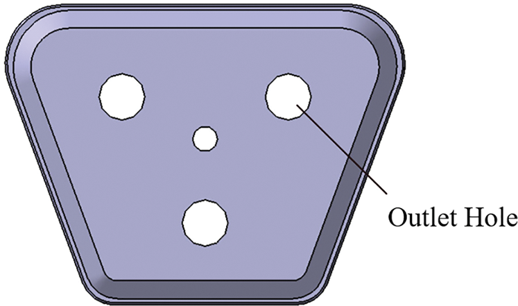
Figure 3: Structure diagram of sealing plug
In the process of hydraulic bulging, tubular parts are often malformed due to the asynchronous axial feed, including wrinkling or cracking. Therefore, to reduce the possibility of forming defects as much as possible, this paper designed a new type of overhead cylinder hydraulic synchronization system which can automatically correct deviation according to the synchronization requirements of hydraulic cylinders on both sides to solve this problem.
3.2 Design of Synchronous Hydraulic System for the Synchronous Overhead Cylinders on Both Sides
In order to implement the synchronous feeding function of synchronous overhead cylinders on both sides, a hydraulic synchronization system of synchronous overhead cylinders on both sides that can automatically correct deviation is designed in this paper, as shown in Fig. 4. The control quantity is the spool displacement of the bidirectional shunt follow-up valve, represented by
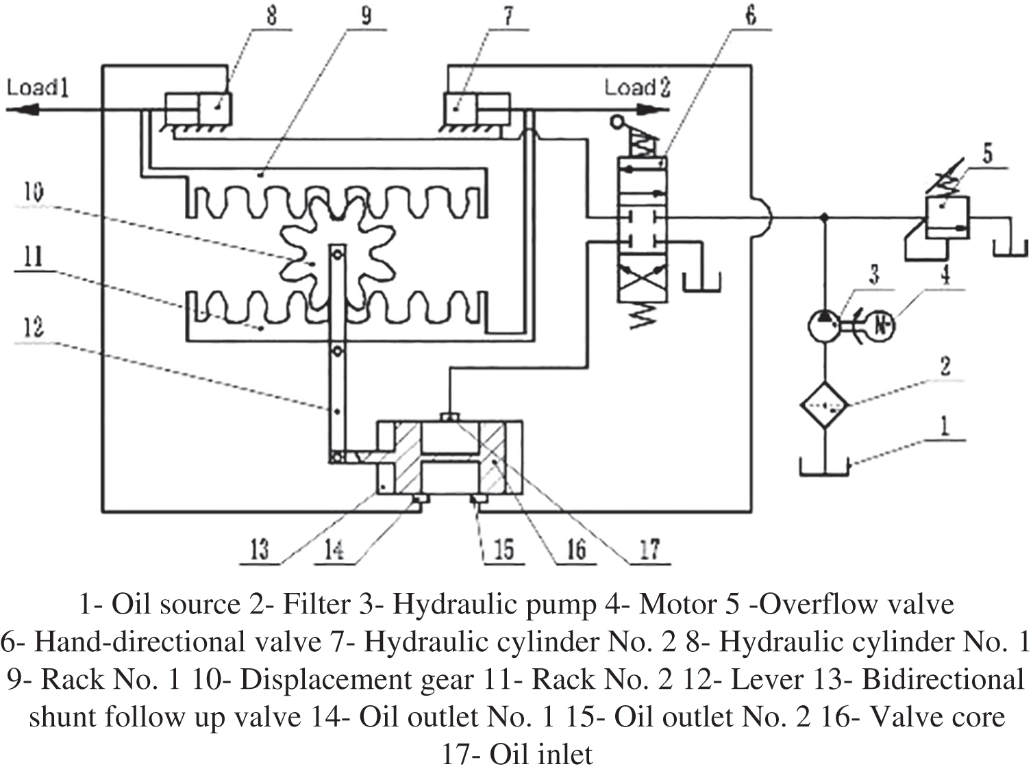
Figure 4: Schematic diagram of hydraulic control system
The motor is used as the power to provide hydraulic oil for the entire hydraulic system, and the two hydraulic cylinders of the system are of the exact specifications. When the system works, the hydraulic oil is connected by the Hand-directional valve to the bidirectional shunt follow-up valve, and the bidirectional shunt follow-up valve will input the oil into two hydraulic cylinders. Due to the exact hydraulic cylinder specifications, the two hydraulic cylinders at this time have the same running speed and have the opposite direction of movement. Because the two racks are connected with the piston rod of the hydraulic cylinder, their movement mode is the same as the hydraulic cylinder. Consequently, the displacement gear position does not shift.
When the speed of the hydraulic cylinder No. 1 is greater than that of hydraulic cylinder No. 2, due to the speed difference, the displacement of the rack No. 1 and the rack No. 2 will produce deviation, resulting in displacement gear position to the right, the expulsion of the gear drives the bidirectional shunt to follow up valve core to the right, to reduce the number of the oil outlet valve throttling area at the same time increase the number of the oil outlet valve orifice size, until the system is stable again.
Similarly, when the speed of the hydraulic cylinder No. 1 is less than that of hydraulic cylinder No. 2, due to the speed difference, the displacement of the rack No. 1 and the rack No. 2 will produce deviation, thus causing the displacement gear position to move to the left. The displacement gear drives the valve spool of the bidirectional shunt follow-up valve to move to the left. Thus, the throttle area of outlet No. 1 is increased while the throttle area of outlet No. 2 is reduced until the system reaches stability again.
3.3 Selection and Calculation of Synchronous Hydraulic System
According to the operation of the synchronous feeding hydraulic system on both sides in the process of hydraulic bulging, the rated pressure of the synchronous hydraulic system is selected as 10 MPa, the loading force
Firstly, the hydraulic cylinder is selected, as shown in Eq. (5). The effective area of the cylinder and the diameter of the piston rod should be determined when the specifications of the hydraulic cylinder are selected, and the specific calculation is made according to the balance of the force on the cylinder. Given that
where:
Ignoring the influence of pressure loss, it is known that the rated pressure of the hydraulic system is 10 MPa. Refer to the mechanical manual, take
Take the data circle D = 80 mm, d = 56 mm, take the hydraulic cylinder damping ratio
The hydraulic pump is then selected, as shown in Eq. (8). As there is pressure loss when hydraulic oil flows, the maximum operating pressure of a hydraulic pump is defined as:
where:
The maximum operating pressure obtained in Eq. (8) is only the static operating pressure of the hydraulic control system. In order to make the hydraulic pump have some reserve pressure, the rated pressure of the hydraulic pump is 1.4 times its static working pressure [19], as shown in Eq. (9), so the rated pressure of the hydraulic pump
As shown in Eq. (10), the hydraulic pump flow is:
where:
Substituting Eq. (11) into Eq. (10), as in Eq. (12), the maximum flow of the hydraulic pump is calculated as:
Check the mechanical manual and refer to the rated pressure of the hydraulic pump
As shown in Eq. (13), the total volume of the hydraulic cylinder
As shown in Eq. (14), the volumetric elastic modulus of hydraulic oil
Then the motor model is selected. In order to provide enough power for the hydraulic pump, the motor should be chosen according to the maximum power of the hydraulic pump [19]. Generally speaking, the actual efficiency of a hydraulic pump is 0.6∼0.8 times the total efficiency, so the maximum efficiency of the pump
where:
Y12S2-2 three-phase asynchronous motor is selected after consulting the mechanical manual, it is Y series three-phase asynchronous motor. Its rated power reaches 7.5 KW, full load speed is 2990 r/min, and rated current is 15 A, which meets the requirements of the hydraulic system.
Then determine the open-loop gain, as shown in Eq. (16), and calculate the open-loop gain K of the system according to the requirement of gain margin. Its value is:
According to the value obtained in Eq. (14), as shown in Eq. (17), it can be calculated as follows:
Then the bidirectional shunt follow-up valve is designed. According to the flow gain required by the system, the slide valve with two convex shoulders, two sides, zero opening, and a rectangular window is selected.
According to the calculation results of the size of the hydraulic cylinder, the initial specification is modified, as shown in Eq. (18). The maximum no-load flow of the spool valve
As shown in Eq. (19), the maximum opening area of the slide valve
where:
As shown in Eq. (20), the spool valve flow gain
where:
As shown in Eq. (21), the feedback gain can be defined as follows from the working principle of synchronous overhead cylinder:
According to Eqs. (7), (17) and (21), Eq. (22) can be obtained. The flow gain of the spool valve
As shown in Eq. (23), the flow gain of the slide valve
As shown in Eq. (24), the area gradient of the slide valve W can be obtained by deforming the above equation:
As shown in Eq. (25), the maximum displacement of the spool
The maximum displacement of the spool
Therefore, a slide valve with a rectangular window without full circumference opening should be used, as shown in Eq. (27). According to the condition that flow saturation is not generated:
where:
As shown in Eq. (28), the following equation can be obtained:
To sum up, the spool diameter
Then determine the pipeline and fuel tank parameters. When the hydraulic oil flow through the pipeline is 13.3 L/min, the allowable liquid flow rate is 1.5 m/s, as shown in Eq. (29), then the inner pipe diameter is:
where:
Therefore, the tubing with an inner diameter of 16 mm and a wall thickness of 2 mm is selected.
The hydraulic oil capacity in the tank is 5∼7 times that of the pump per minute in the case of a medium pressure system [19]. At this time, take 6 times, as shown in Eq. (30), then the tank capacity is:
Finally, the system pressure loss is checked. The system pressure loss includes the pressure loss along the pipeline
where:
As shown in Eq. (34), the total pressure loss
According to the above, the inner diameter of the tubing d is 16 mm, as shown in Eq. (35), the hydraulic oil flow rate in the tubing is:
As shown in Eq. (36), Reynolds number
where:
From Eq. (36),
According to experience, the local pressure loss of the pipeline is 0.1 times the pressure loss along the pipeline, as shown in Eq. (38):
As shown in Eq. (39), the pressure loss of relief valve and manual reversing valve in the hydraulic system is 0.3 MPa under nominal pressure, therefore, the local pressure loss
According to Eqs. (37)–(39), Eq. (40) can be obtained, and system pressure loss
According to Eq. (8), the estimated value of system pressure loss,
3.4 Simulation of Synchronous Hydraulic System
In order to explore whether the designed synchronous hydraulic system of automatic correction can be established, the AMESim simulation software is used to simulate the synchronous hydraulic system. By adjusting the parameters of each component, the displacement curves of the two-cylinder piston rod under the given loading conditions are obtained.
First, the model is built in AMESim, as shown in Fig. 5. The middle rack and pinion are replaced by differential, the speed difference is converted into displacement difference, and a 1:1 isometric lever is set. The rest is retrieved from the component library, and the interfaces of each component are connected to complete the model building.

Figure 5: Diagram of hydraulic system modeling
In order to explore the automatic deviation correction performance of the hydraulic synchronous loop designed in this paper, two different working conditions are set for the model, the selection of other components as described above, the simulation time is set to 10 s. The displacement of the piston rod is 80 mm, and the displacement curve of the valve core in the middle of the two-cylinder piston rod and the bidirectional shunt follow-up valve is obtained.
Firstly, the same load was analyzed. In the first working condition, 18 kN load was applied to the Nos. 1 and 2 hydraulic cylinders. After simulation, displacement curves of the piston rod of the two cylinders and the displacement curves of the valve core in the middle of the two-way shunt follow-up slide valve were obtained, as shown in Figs. 6 and 7.
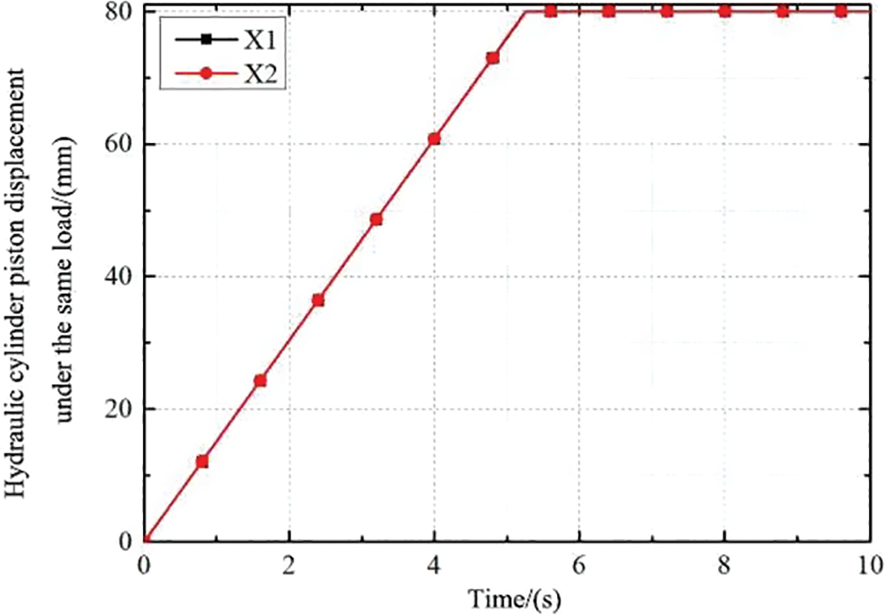
Figure 6: Displacement curve of two cylinder piston rod
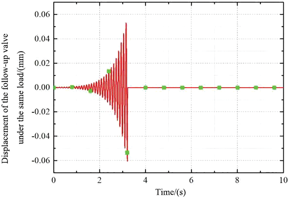
Figure 7: Follow-up valve spool displacement curve
Fig. 6 shows that the displacement curves of the two piston rods coincide entirely, and the synchronization of the hydraulic synchronization system is high. The displacement reaches 80 mm at about 5.1 s. Fig. 7 shows that the displacement of the valve spool of the follow-up valve reaches the stable middle position at about 3.1 s after early adjustment. At this time, the flow of the two ports is equal, and the spool of the follow-up valve does not move anymore.
In the second working condition, 18 kN load is applied to hydraulic cylinder No. 1 and 17 kN load to hydraulic cylinder No. 2. After simulation, displacement curves of the piston rod of two cylinders are obtained as shown in Fig. 8, and displacement curves of valve core in the middle of bi-directional shunt follow-up slide valve are obtained as shown in Fig. 9.
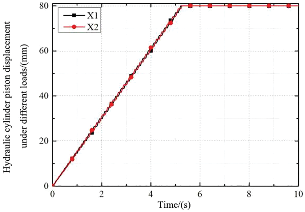
Figure 8: Displacement curve of two cylinder piston rod
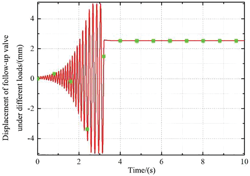
Figure 9: Diagram of displacement curve of valve spool of follow-up valve
It can be seen from Fig. 8 that the displacement of the two piston rods has a certain deviation between 0∼5.1 s, and the displacement of the two cylinders around 5.1 s reaches a stable position of 80 mm, and the displacement curves of the two piston rods coincide completely to realize synchronization, indicates that the system can recognize the automatic deviation correction function. Fig. 9 shows that the spool displacement of the follow-up valve under different loads reaches a stable position at about 3.1 s after early adjustment, and the spool moving distance is about 2.5 mm at this time.
Finally, the simulation results are compared and analyzed, and the displacement errors of the piston rods of the two hydraulic cylinders in Figs. 6 and 8 are derived. The conclusion can be drawn by observing the change of displacement error with time.
As shown in Fig. 10, the synchronous overhead cylinder hydraulic synchronization system can realize automatic deviation correction and ensure the synchronous displacement of the two overhead cylinders to meet the purpose of guaranteeing the forming quality of parts by hydraulic expansion mold of torsion beam. When the load pressure of the two hydraulic overhead cylinders is the same, the piston rod of the two cylinders moves synchronously, and the displacement error is 0 mm. When the load pressure of the two hydraulic overhead cylinders is different, the following valve can adjust the throttle area of the valve outlet of the two cylinders according to the displacement of the spool to achieve an automatic deviation correction function; the system has been verified successfully.
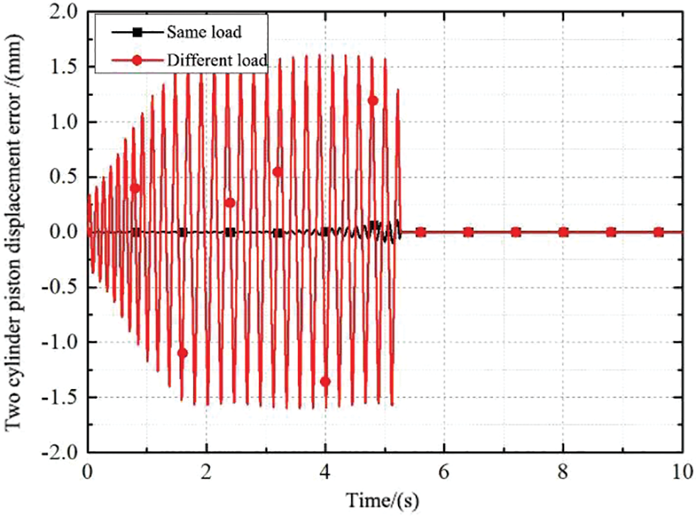
Figure 10: Diagram of two cylinder piston rod displacement error curve
4 Research on Synchronous Hydraulic System of Overhead Cylinder
4.1 Establishment of Mathematical Model for a Synchronous System of Overhead Cylinders
In order to further study the control characteristics of the synchronous system of the overhead cylinder, a mathematical model of the hydraulic control system is established and simulated in Simulink. The system block diagram is shown in Fig. 11.
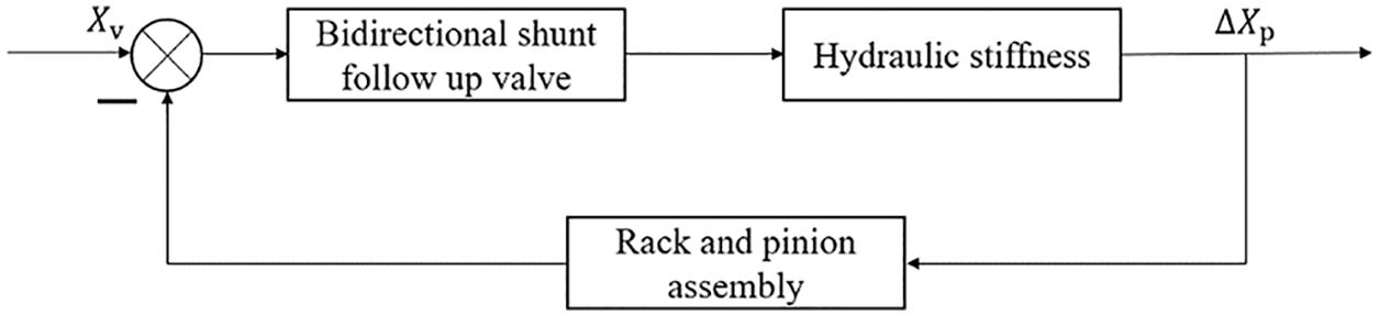
Figure 11: Block diagram of the hydraulic control system
To determine the feedback gain, this paper designs the gear lever as a critical part of the feedback control that is crucial for the whole hydraulic synchronization synchronous system, based on the above analysis of the agency gear center horizontal displacement speed, speed when the relationship is determined, as the same time, the displacement relationship is defined.
As shown in Fig. 12, the upper and lower rack move in a reverse straight line. In order to calculate the horizontal displacement distance of the center point O of the middle gear when the speed difference between the upper and lower rack is
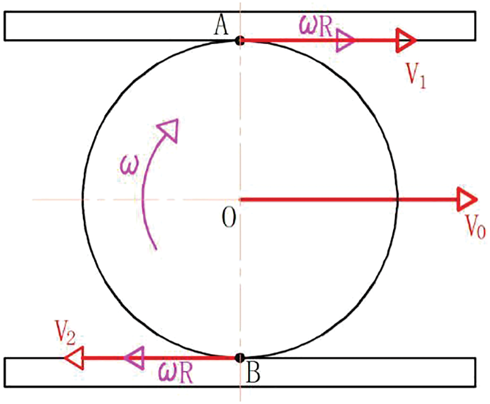
Figure 12: Schematic diagram of rack and pinion model
If the motion direction of
Subtract Eq. (42) from Eq. (41) to get Eq. (43):
Similarly, it can be judged that when
4.2 Analysis of Response Characteristics of Overhead Cylinder Synchronous System
According to the system block diagram, the flow equation of the follow-up spool valve is established, as shown in Eq. (45):
where:
According to Bernoulli equation, the flow through two hydraulic cylinders can be expressed in the following formula, as shown in Eqs. (46) and (47):
where:
where:
Eq. (48) can be obtained from Eqs. (46) and (47):
Eq. (48) is linearized to obtain the pressure-flow characteristics near zero, as shown in Eq. (49):
where:
where:
Idealize the connected pipe and its internal parameters. The dynamic parameters are ignored, the oil pressure in the hydraulic cylinder is equal everywhere, and the oil temperature and other parameters do not change with time. The leakage of the hydraulic system is regarded as laminar flow [20]. The load flow can be expressed by Eqs. (52)–(54):
where:
Its rotation deviation is shown in Eq. (55):
where:
The total compression volume is shown in Eq. (56), and the load flow is shown in Eq. (57):
where:
Then the force balance equation of the hydraulic cylinder and the load is established. According to Newton’s second law [21], the balanced equation of the output force and the load force of the hydraulic cylinder can be obtained, as shown in Eq. (58):
where:
Eqs. (49), (57) and (58) are the three basic equations of the valve-controlled hydraulic cylinder. The Laplace transform of the three equations is as follows (59)–(61):
After the conversion of the above three expressions, Eq. (62) can be obtained:
Hydraulic system load is mainly divided into elastic load and inertia load, but in the servo system often elastic load is very small and ignored, so we only consider the inertia load [22]. In this formula, the velocity of the piston is so large that the velocity generated by leakage and viscosity of the other terms can be ignored. When K = 0, Eq. (62) can be simplified into Eq. (63):
Plus the feedback gain
According to Eq. (14), hydraulic natural frequency
Eq. (65) is put into the Simulink simulation model in Fig. 13 for simulation analysis, and the step response curve of the hydraulic synchronous system is obtained.
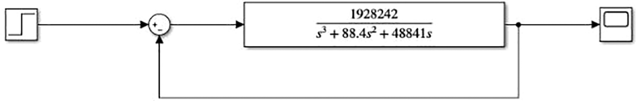
Figure 13: Simulation diagram of synchronous hydraulic system transfer function
As shown in Fig. 14, when the stop signal is input, the system responds at about 0.1∼0.2 s and reaches the equilibrium state at about 0.2 s. The system has no overshoot, and the output signal can match the input signal, which verifies the control characteristics of the synchronous control system of the overhead cylinder. The control system has good performance and meets the design requirements.
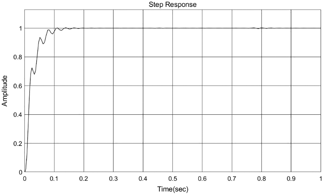
Figure 14: Step response curve of synchronous hydraulic system
(1) The product structure of the automotive torsion beam is designed, and its basic dimensions are determined as follows: length is 1260 mm, the maximum height difference is 85.2 mm, the surface area is 0.356 m², basic wall thickness is 3 mm, parts are symmetrical; the process flow of the parts is determined, the initial tube blank is selected, and the process parameters related to hydraulic bulging are calculated. The hydraulic expansion mold structure of the automotive torsion beam is designed. According to the actual processing conditions and the synchronization requirements of hydraulic cylinders on both sides, a new type of synchronous hydraulic system of the overhead cylinder which can automatically correct deviation is designed. The movement parameters of the cylinders on both sides during the processing of torsion beam are determined, and each part is selected.
(2) Modeling and simulation are completed in AMESim, and synchronization curves of displacement of two cylinders piston rod are obtained under two working conditions. When the load pressure of two hydraulic overhead cylinders is the same, the movement of the two cylinders’ piston rod is synchronous, and the displacement error is 0 mm. When the load pressure of the two hydraulic overhead cylinders is different, the following valve can adjust the throttle area of the two cylinders’ valve outlet according to the spool’s displacement to achieve an automatic deviation correction function and the system has been verified successfully.
(3) The mathematical modeling of the control system is completed, and the step response curve of the system is successfully obtained in Simulink. The results show that the response action of the system is generated at about 0.1∼0.2 s, and the system reaches the equilibrium state at about 0.2 s. There is no overshoot in the system, and the output signal can match the input signal, which verifies the control characteristics of the overhead cylinder synchronous control system. The performance of the control system is good and meets the design requirements.
Funding Statement: This article belongs to the major projects of “The University Synergy Innovation Program of Anhui Province (GXXT-2019-004); Teaching Research Project of Anhui Education Department; Science and Technology Planning Project of Wuhu City (2021YF58).”
Conflicts of Interest: The authors declare they have no conflicts of interest to report regarding the present study.
References
1. Ali, H. H., Mustafa, A. W., Al-Bakri, F. F. (2021). A new control design and robustness analysis of a variable speed hydrostatic transmission used to control the velocity of a hydraulic cylinder. International Journal of Dynamics and Control, 9(3), 1078–1091. [Google Scholar]
2. Pendyala, V. K., Sukumar, T. (2021). Modeling and simulation of lift axle control system at vehicle level using AMESim. SAE Technical Paper. [Google Scholar]
3. Kumar, A., Dasgupta, K., Das, J. (2017). Analysis of decay characteristics of an accumulator in an open-circuit hydrostatic system with pump loading. Proceedings of the Institution of Mechanical Engineers, Part I: Journal of Systems and Control Engineering, 231(4), 312–326. [Google Scholar]
4. Yahya, A. T. A. M., Chen, S. Y. (2020). Research on simulation analysis of valveless hydraulic servo system. IOP Conference Series: Earth and Environmental Science, 546(5), 052006. [Google Scholar]
5. Mishra, S. K., Wrat, G., Ranjan, P., Das, J. (2018). PID controller with feed forward estimation used for fault tolerant control of hydraulic system. Journal of Mechanical Science and Technology, 32(8), 3849–3855. [Google Scholar]
6. Feng, K., Deng, B., Zha, C. (2021). An AMESim-based simulation of hydraulic system design for ultra-high pressure tablet presses. Journal of Physics: Conference Series, 1983(1), 012033. [Google Scholar]
7. Yu, J., Wang, Z., Zhang, H. (2021). Research on pressure pulsation of piling hammer hydraulic system based on AMESim. IOP Conference Series: Earth and Environmental Science, 781(2), 022072. [Google Scholar]
8. Shen, W., Liu, S., Liu, M. (2021). Adaptive sliding mode control of hydraulic systems with the event trigger and finite-time disturbance observer. Information Sciences, 569, 55–69. [Google Scholar]
9. Bao, Z., Zeng, D. (2019). Optimization of variable frequency hydraulic system of filling machine based on fuzzy adaptive control. IOP Conference Series: Earth and Environmental Science, 252(3), 1–4. [Google Scholar]
10. Liu, Z., Wang, H., Xiong, Z., Huo, J., Zhan, J. et al. (2021). Modeling and research of fuzzy PID control strategy for hydraulic rock drill propulsion system. Journal of Physics: Conference Series, 1820(1), 012188. [Google Scholar]
11. Nguyen, D. D., van Chu, D. (2021). Dynamic analysis and simulation of the hydraulic control system on the remote-controlled explosive ordnance disposal machine. International Journal of Manufacturing, Materials, and Mechanical Engineering, 11(3), 37–54. [Google Scholar]
12. Kittisares, S., Hirota, Y., Nabae, H., Endo, G., Suzumori, K. (2022). Alternating pressure control system for hydraulic robots. Mechatronics, 85, 102822. [Google Scholar]
13. Yang, K., Wang, Y., Fu, K. (2021). Design of hydraulic bulging die for automobile torsion beam and optimization of forming process parameters. Advances in Materials Science and Engineering, 2021, 2–3. [Google Scholar]
14. Dukalski, P., Będkowski, B., Parczewski, K., Wnęk, H., Urbaś, A. et al. (2021). Analysis of the influence of motors installed in passenger car wheels on the torsion beam of the rear axle suspension. Energies, 15(1), 1–20. [Google Scholar]
15. Yeole, P., Kim, S., Hassen, A. A., Kumar, V., Kunc, V. et al. (2021). Large-scale additive manufacturing tooling for extrusion-compression molds. Additive Manufacturing Letters, 1, 100007. [Google Scholar]
16. Peng, Y. D. (2019). Simulation analysis of internal high pressure forming of torsion beam based on fluid-structure coupling method (Master Thesis). Guangxi University of Science and Technology, China. [Google Scholar]
17. Solazzi, L., Buffoli, A. (2021). Fatigue design of hydraulic cylinder made of composite material. Composite Structures, 277, 114647. [Google Scholar]
18. Zhu, B. (2018). Research on active disturbance rejection control of oil film thickness test bench for hydrostatic guide of machine tool (Master Thesis). Anhui Polytechnic University, China. [Google Scholar]
19. Nayak, S., Rao, M. (2021). Design and development of a flexurally amplified piezoelectric actuator based piezo-hydraulic pump. Materials Today: Proceedings, 46, 9956–9965. [Google Scholar]
20. Ghazaly, N. M., Moaaz, A. O. (2020). Hydro-pneumatic passive suspension system performance analysis using AMESim software. International Journal of Vehicle Structures & Systems, 12(1), 9–12. [Google Scholar]
21. Siddique, M. A. A., Kim, W. S., Kim, Y. S., Kim, T. J., Choi, C. H. et al. (2020). Effects of temperatures and viscosity of the hydraulic oils on the proportional valve for a rice transplanter based on PID control algorithm. Agriculture, 10(3), 73. [Google Scholar]
22. Alekseenkov, A. S., Erofeev, E. V., Khaletskiy, L. V. (2020). Experimental research of dynamic characteristics of electro-backup hydraulic actuator at the load test-rig of flight control systems. IOP Conference Series: Materials Science and Engineering, 734(1), 012015. [Google Scholar]
Cite This Article
 Copyright © 2023 The Author(s). Published by Tech Science Press.
This work is licensed under a Creative Commons Attribution 4.0 International License , which permits unrestricted use, distribution, and reproduction in any medium, provided the original work is properly cited.
 Downloads
 Citation Tools