 Open Access
ARTICLE
Comparative Study of Two Materials Combining a Standard Building Material with a PCM
1 Research Laboratory in Industrial Eco-innovation and Energetics (LR2E), ECAM-EPMI, Cergy-Pontoise, 95000, France
2 Laboratory of Mechanic and Materials of Civil Engineering (L2MGC), University of Cergy-Pontoise, Cergy-Pontoise, 95000, France
3 Historical Monuments Research Laboratory (LRMH), Champs-sur-Marne, 77420, France
* Corresponding Author: Marwa El Yassi. Email:
(This article belongs to the Special Issue: Materials and Energy an Updated Image for 2021)
Fluid Dynamics & Materials Processing 2023, 19(5), 1283-1290. https://doi.org/10.32604/fdmp.2022.023183
Received 13 April 2022; Accepted 20 July 2022; Issue published 30 November 2022
Abstract
Phase change materials (PCMs) have the ability to store thermal energy and make it available at a later stage to keep indoor temperature within a specific range and achieve better thermal comfort in buildings. This study focuses on the performances of materials obtained by combining a standard building material with a PCM. In particular, two different materials mixed with the same PCM are considered under the same climatic conditions. The related thermal behavior is assessed in the framework of numerical simulations conducted with ANSYS Fluent assuming parameters representative of a city located in Europe. The results show that the addition of PCM to concrete and bricks can improve the thermal inertia of the resulting material.Keywords
Nomenclature
| H | Enthalpy [J/kg] |
| λ | Thermal conductivity [W/(m.K)] |
| T | Temperature [K] |
| ρ | Density [kg/m3] |
| Cp | Specific heat capacity [J/(kg.K)] |
| Capp. | Apparent specific heat capacity [J/(kg.K)] |
| L | Latent heat [kJ/kg] |
| t | Time [s] |
| Tout | Outside temperature [K] |
| Tin | Inside temperature [K] |
| h | Convective heat transfer coefficient [W/(m2.K)] |
In recent years, the building industry has accounted for the largest share of energy overconsumption, and interest in this sector is growing. To cope with this overconsumption of energy, several suitable methods are applied in the building sector to reduce energy consumption. The main challenge of tomorrow’s building is to avoid passive cooling and heating systems. One of the solutions is the integration of smart materials in the building walls.
Several researches have studied the addition of phase change materials: a material having the capacity to store energy during the day and to restore it during the night in order to smooth the temperature fluctuations in case of overheating and specially to limit the summer discomfort. This new solution has the advantage of limiting the energy consumed by the various equipment intended for the comfort of the habitat. These materials can be integrated or combined with other construction materials such as plaster or gypsum [1–3], concrete [4–6] and other matrices [7,8]. However, studies comparing solutions in combination with concrete and brick remain rare in the literature.
The objective of this paper is to compare the same PCM with two ubiquitous building materials in construction: brick and concrete, and to evaluate their influence on temperature distribution and their impact on the reduction of internal wall temperature through numerical modeling. The numerical simulation was solved with the finite volume method integrated in the commercial software Ansys Fluent.
Two different materials are chosen with the same PCM under the same climatic conditions: brick and concrete with the PCM Energain manufactured by DuPont.
The thermo-physical properties of PCM wallboard [9], concrete and brick [10] are listed in Tables 1 and 2.


The effect of placement in a multi-layer wall of a PCM composite wall panel has been studied previously which showed that there is an optimized location for placement of PCM in building envelope surfaces based on its effectiveness on interior temperature control: Externally located composite PCM wall panels performed better than internally located composite PCM panels in multilayer wall systems during cooling seasons.
In this study, the PCM panel is used in the outside of the wall. From exterior to interior, the wall layer is the PCM panel of 5.3 mm thickness, followed by the building material layer (concrete or brick) with the thickness of 15 cm.
In this study, the PCM panel is used in the outside of the wall. From exterior to interior, the wall layer is the PCM panel of 5.3 mm thickness, followed by the building material layer (concrete or brick) with the thickness of 15 cm.
The model is described in Fig. 1 and has been validated by comparison with an analytical solution and a numerical study [11]. Two types of boundary conditions were imposed on the inner wall: Dirichlet-type condition (Case 1) and natural convection condition (Case 2) shown in Table 3. The assumptions made to simplify the equation are listed below:
- The flow is considered laminar.
- The material is pure and homogeneous.
- Heat transfer through the wall is one-dimensional in unsteady regime.
- Integration of conduction regime.
- All other heat transfer phenomena are neglected.
- The horizontal walls are considered in adiabatic conditions.
- The thermal conduction follows the Fourier law: q = −λ ∂T/∂x.
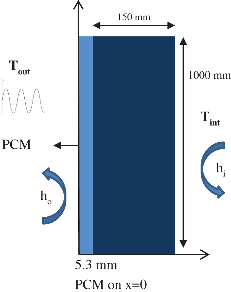
Figure 1: Schematic representation of the wall

The general energy conservation equation has been simplified with the apparent Cp method as follows (1):
With Capp, the apparent specific heat capacity in J/(kg.K).
For the phase change phenomenon, L representing the latent heat is taken into account as below:
With
The imposed temperature is a sinusoidal approximation to simulate the real temperatures, in order to define the hottest days during the hot season in Paris, which represents the peak of summer discomfort for residents, during 24 h (a day) [8]:
With the time t in seconds.
Please note that the results were evaluated at the surface of the wall with/without the PCM.
Case 1:
Fig. 2 shows the surface temperature distribution in the concrete wall and the PCM/concrete. It was noted that compared to the reference wall, the bilayer with the presence of the PCM layer has lower temperatures. The surface temperature distribution within the brick wall and the PCM/brick wall at t = 12 h is shown in Fig. 2. Low temperatures can be observed locally, due to the addition of a PCM plate to the brick.
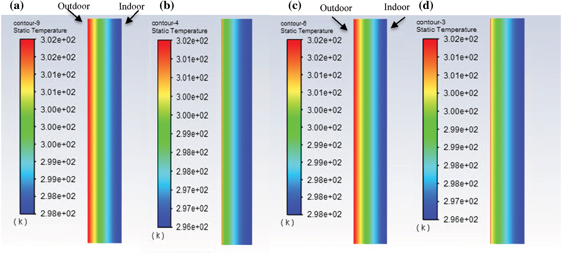
Figure 2: Temperature distribution within the concrete wall of concrete (a), PCM/concrete (b), wall of brick (c) and PCM/brick (d)
Fig. 3 illustrates the evolution of the surface temperature of the two walls by 24 h. It can be seen that a significant result is obtained in terms of temperature reduction. In comparison with the reference concrete, the temperature of PCM/concrete can be reduced by 1.5 K. In addition, a phase shift of the order of 2 h between the two peaks of the two walls is observed.
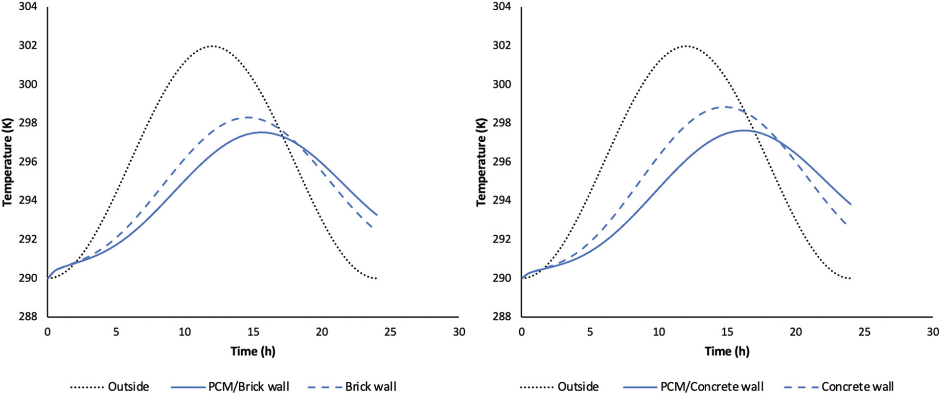
Figure 3: Evolution of the surface temperature of the concrete and brick wall with and without PCM
This figure presents also the evolution of the surface temperature of brick with and without PCM. A temperature reduction of 0.8 K was measured on the wall with phase change materials compared to the brick without PCM. A phase shift of 2 h between the two temperature peaks was noted.
In this case, we can observe that the amplitudes of the oscillations were greatly affected for the wall including the panel of PCM. It can be noted that the PCM/concrete have the ability to keep the wall temperature cooler than the PCM/Brick and to reduce the surface temperature of the wall more efficiently.
Case 2:
The surface temperature distribution within the concrete wall and the PCM /concrete wall at t = 12 h is shown in Fig. 4. Very low temperatures can be observed locally, due to the addition of a PCM to the reference concrete.
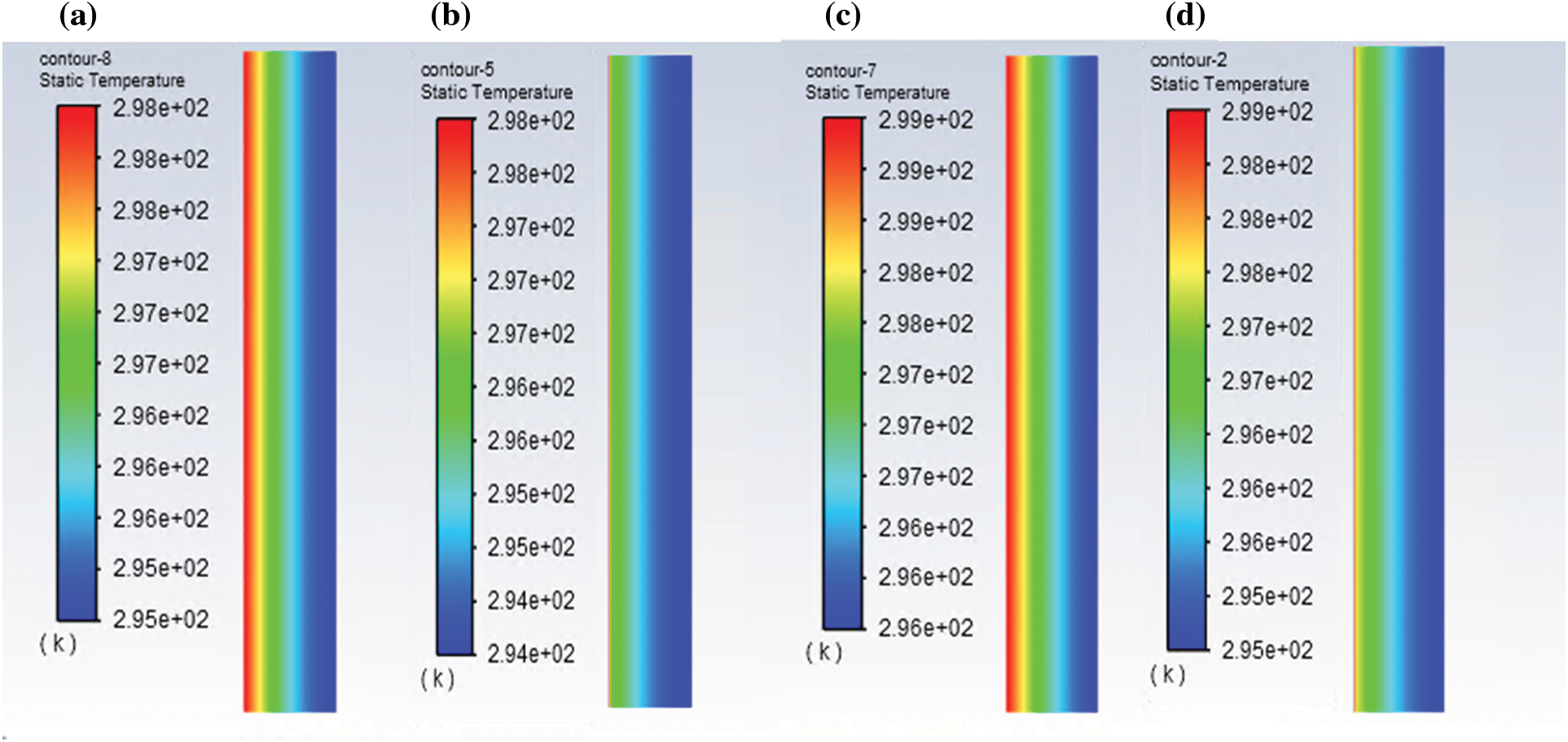
Figure 4: Temperature distribution within the concrete wall (a), PCM/concrete (b), wall of brick (c) and PCM/brick (d)
For the case of the brick, the presence of the isothermal lines show lower temperatures at the wall with PCM.
Fig. 5 illustrates the evolution of the surface temperature of the concrete wall and the PCM/concrete. There is a significant difference between the wall with and without PCM in terms of reduction of temperature fluctuations. Indeed, there is a drop in the internal wall temperature of about 1.5 K recorded, with a phase shift noted between the two temperature peaks of 2 h. We can underline that the wall temperature with brick and PCM is slightly lower than the reference wall temperature. Indeed, a maximum drop of 0.8 K was noted at temperature after a calculation time of about 16.5 h. It was also observed a phase shift of temperature peaks of 2 h.
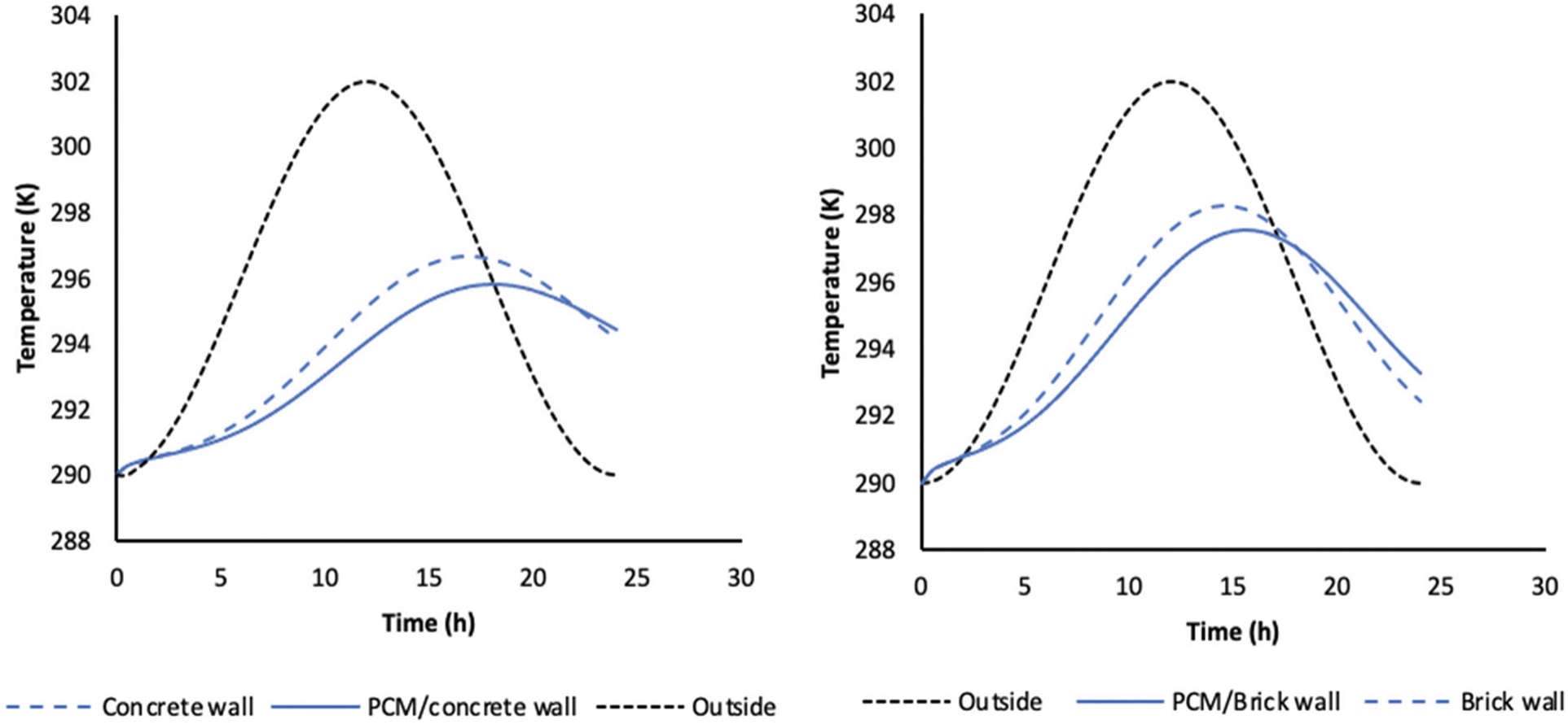
Figure 5: Evolution of the surface temperature of the concrete and brick wall with and without PCM
The results of the two building materials with PCM allows us to highlight the difference in temperature fluctuations between the wall with and without phase change materials in the case of brick and concrete. Both materials show significant results with the integration of the panel with PCM.
By contrast, it can be clearly seen that the concrete has a better influence on the temperature distribution than Brick due their thermal properties.
It can be seen that the PCM plays the role of an insulator at t = 12 h for all cases since it is in the liquid state, which means that it is in the energy storage phase.
Moreover, for all cases, it is observed that the amplitudes of the oscillations were greatly affected for the wall including the panel with phase change materials. This result was therefore put forward by determining the decrement factor for each case, which is a ratio between the two values of the amplitudes to that of the reference wall and that of the wall with PCM. The final aim is to improve the thermal comfort of a room. The lower this value, the lower the thermal amplitude compared to the reference wall and the more the wall has optimized and isolated the interior temperatures.
The Table 4 below illustrates the difference in amplitudes for each case, its decrement factor and the phase shift between the wall with and without PCM. It can be seen that better damping was achieved in the concrete case with the addition of a single panel of phase change material.

This paper presents a numerical study to solve one dimensional transient heat transfer through the bilayer surfaces of the building envelope. The aim is to compare two building materials with the same phase change material whose phase change temperatures are well suited to the Parisian climate.
The addition of the PCM panel showed a different behavior between the two materials due to their thermal properties. The results reveal an interesting and significant potential in terms of temperature reduction within the wall. In addition, a phase shift of temperature peaks was recorded, resulting in a good thermal inertia when integrating the PCM plate.
On one hand, this comparative study showed the influence of a phase change material on the reduction of the temperature of a wall and on the improvement of the thermal inertia. On the other hand, it was found that the construction material also plays a major role in the results obtained. This highlights the importance of choosing the best combination: PCM and the building material.
In perspectives, further studies must be carried out to evaluate other types of PCM with these building materials while getting as close as possible to the real case.
Funding Statement: The authors received no specific funding for this study.
Conflicts of Interest: The authors declare that they have no conflicts of interest to report regarding the present study.
References
1. M’ghari, O., Hassani, F., Mekhzoum, M., Zari, N., Bouhfid, R. et al. (2021). Elaboration of a composite material based on plaster reinforced with phase change material/Oakum Fiber: Physical, thermal and mechanical properties. Journal of Energy Storage, 35, 102321. [Google Scholar]
2. Borreguero, A., Serrano, A., Garrido, I., Rodríguez, F., Carmona, M. (2014). Polymeric-SiO2 for improving the thermal properties of gypsum applied in energy efficient buildings. Energy Conversion and Management, 87, 138–144. [Google Scholar]
3. Conrad, V., Kornadt, O., Ostry, M. (2008). Temperature reduction due to the application of phase change materials. Energy and Building, 40(5), 937–944. [Google Scholar]
4. Cabeza, L., Castellón, C., Nogués, M., Medrano, M., Leppers, R. et al. (2007). Use of microencapsulated PCM in concrete walls for energy savings. Energy and Building, 39(2), 113–119. [Google Scholar]
5. Memon, A., Cui, H., Zhang, H., Xing, F. (2015). Utilization of macro encapsulated phase change materials for the development of thermal energy storage and structural lightweight aggregate concrete. Applied Energy, 139(1), 43–55. [Google Scholar]
6. Stritih, U., Tyagi, V. V., Stropnik, R., Paksoy, H., Haghighat, F. et al. (2018). Integration of passive PCM technologies for net-zero energy buildings. Sustainable City and Society, 41(6), 286–295. DOI 10.1016/j.scs.2018.04.036. [Google Scholar] [CrossRef]
7. Ahmad, M., Bontemps, A. (2006). Thermal testing and numerical simulation of a prototype cell using light wallboards coupling vacuum isolation panels and phase change material. Energy and Buildings, 38(6), 637–681. DOI 10.1016/j.enbuild.2005.11.002. [Google Scholar] [CrossRef]
8. Rao, Z., Taotao, X., Chenzhen, L., Zheng, Z., Liang, L. et al. (2018). Experimental study on thermal properties and thermal performance of eutectic hydrated salts/expanded perlite form-stable phase change materials for passive solar energy utilization. Solar Energy Materials and Solar Cells, 188(2–3), 6–17. DOI 10.1016/j.solmat.2018.08.012. [Google Scholar] [CrossRef]
9. Kuznik, F., Virgone, F. (2009). Experimental investigation of wallboard containing phase change material: Data for validation of numerical modeling. Energy and Buildings, 41(5), 561–570. DOI 10.1016/j.enbuild.2008.11.022. [Google Scholar] [CrossRef]
10. Mourid, A., El Alami, M., Kuznik, F. (2018). Experimental investigation on thermal behavior and reduction of energy consumption in a real scale building by using phase change materials on its envelope. Sustainable Cities and Society, 41(11), 35–43. DOI 10.1016/j.scs.2018.04.031. [Google Scholar] [CrossRef]
11. Younsi, Z., Naji, H. (2017). Numerical simulation of the thermal behavior of a brick wall incorporating microcapsules of phase change materials via the enthalpic method. 25th French Congress of Thermal Engineering, France. [Google Scholar]
12. Sarra, D. (2015). Development of new “energy storage” concretes: Experimental, probabilistic and numerical investigations of thermal behavior (Ph.D. Thesis). University of Paris, France. [Google Scholar]
Cite This Article
 Copyright © 2023 The Author(s). Published by Tech Science Press.
This work is licensed under a Creative Commons Attribution 4.0 International License , which permits unrestricted use, distribution, and reproduction in any medium, provided the original work is properly cited.


 Submit a Paper
 Propose a Special lssue
 View Full Text
 Download PDF
 Downloads
 Citation Tools