
 Submit a Paper
 Propose a Special lssue
 Open Access
ARTICLE

Effect of an Internal Heat Exchanger on the Performances of a Double Evaporator Ejector Refrigeration Cycle
1 Mechanical Engineering Department, Badji Mokhtar University, Annaba, Algeria
2 Center for Thermal Sciences of Lyon, INSA, Villeurbanne, France
* Corresponding Author: Latra Boumaraf. Email:
(This article belongs to the Special Issue: Materials and Energy an Updated Image for 2021)
Fluid Dynamics & Materials Processing 2023, 19(5), 1115-1128. https://doi.org/10.32604/fdmp.2022.022674
Received 20 March 2022; Accepted 17 May 2022; Issue published 30 November 2022
 View Full Text
 Download PDF
Abstract
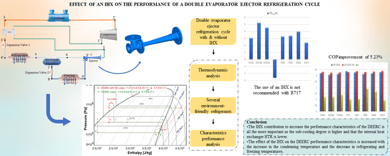
A theoretical investigation is presented about a double evaporator ejector refrigeration cycle (DEERC). Special attention is paid to take into account the influence of the sub-cooling and superheating effects induced by an internal heat exchanger (IHX). The ejector is introduced into the baseline cycle in order to mitigate the throttling process losses and increase the compressor suction pressure. Moreover, the IHX has the structure of a concentric counter-flow type heat exchanger and is intentionally used to ensure that the fluid at the compressor inlet is vapor. To assess accurately the influence of the IHX on the DEERC performance, a mathematical model is derived in the frame of the dominant one-dimensional theory for ejectors. The model also accounts for the friction effect in the ejector mixing section. The equations of this model are solved using an Engineering Equation Solver (EES) for different fluids. These are: R134a as baseline fluid and other environment friendly refrigerants used for comparison, namely, R1234yf, R1234ze, R600, R600a, R290, R717 and R1270. The simulation results show that the DEERC with an IHX can achieve COP (the coefficient of performance) improvements from 5.2 until 10%.Graphic Abstract
Keywords
Nomenclature
| Abbreviations | |
| DEERC | Double evaporator ejector refrigeration cycle |
| IHX | Internal heat exchanger |
| Symbols | |
| C | Coefficient in Eq. (17) |
| COP | Coefficient of performance |
| f | Friction factor |
| HTR | Heat transfer ratio |
| PLR | Ejector pressure lift ratio (=P1/P9) |
| PR | Compressor pressure ratio |
| U | Entrainment ratio |
| x | Quality |
| 1, 2, etc. | Locations in the cycle |
| Greek symbols | |
| η | Nozzle efficiency |
| Ф | Ejector area ratio |
| Subscripts | |
| comp | Compressor |
| C | Condenser |
| d | Diffuser |
| e | Exit |
| ev1 | Refrigerating evaporator |
| ev2 | Freezing evaporator |
| imp | Improvement |
| o | Outlet |
| P | Primary nozzle or fluid |
| S | Secondary nozzle or fluid |
| Superscripts | |
| L | Liquid saturation |
| n | Coefficient in Eq. (17) |
| V | Vapor saturation |
| * | Throat |
Refrigeration technology plays a critical role for human beings’ food and comfort; about 15%–20% of the world’s electricity produced is used in refrigeration and air conditioning applications [1]. Energy efficiency and its relationship are an important part of modern refrigeration system. In order to reduce its energy consumption, many studies on energy efficiency have been carried out by several researchers but have not reached a satisfactory level until now. Indeed, important efforts have been dedicated to enhancing the vapor compression cycle performance, including modifying baseline cycle, optimizing cycle system configurations, using more efficient refrigerants and developing better compressors [2].
Among these solutions is the ejector refrigeration system [3,4], where the ejector is used as an expansion device to recovering the energy loss during the expansion process. For such solution, it should be noted that both of the system energy efficiency and the ejector performance are considerably affected by the ejector geometry, operating conditions and the nature of the working fluid [5].
Another solution is obtained by the integration of an internal heat exchanger (IHX) to provide subcooling. The typical configuration of the internal heat exchanger in refrigeration systems is such that before penetrating into the compressor, the vapor is superheated by absorbing the heat of the liquid refrigerant leaving the condenser. Several studies have stated the beneficial effect of an IHX on the coefficient of performance and the cooling capacity of a refrigeration system [6,7].
This study focuses on the investigation of the influence of an IHX on a DEERC performance [8,9]. The fluids considered in this work are R134a (baseline) and other environment-friendly refrigerants: R1234yf, R1234ze, R600, R600a, R290, R1270 and R717. In addition, the effects of operating conditions as well as those of several parameters such as the sub-cooling value and that of the HTR (Heat Transfer Ratio) of the internal heat exchanger on the system performance were also examined.
The considered DEERC system schematic diagram (as shown in Fig. 1) consists of an ejector, two evaporators, compressor, gas-liquid separator, condenser, and two expansion devices. The ejector configuration is described in Fig. 2.

Figure 1: DEERC’s schematic diagram

Figure 2: Ejector configuration
A superheated vapor refrigerant in state of point (1) at low temperature and pressure is compressed to condenser pressure with an isentropic efficiency ηcomp. The fluid in state of point (2) leaving the compressor, toward the condenser where it condenses to state of point (3) by releasing heat to the environment. Thereafter, the refrigerant in liquid form, leaving the condenser, enters the refrigerating evaporator through the throttling valve 1 located between the points (3) and (4). Then, by flowing into the gas-liquid separator, the two-phase fluid leaving the refrigerating evaporator in state of point (5) is divided into two dissimilar states; saturated vapor and saturated liquid. While the saturated vapor at state of point (6) flows toward the ejector, the saturated liquid at state of point (7) enters the conventional expansion device 2 and expands to the freezing evaporator pressure at state of point (8). After that, the fluid entering the freezing evaporator is vaporized to state of point (9), realizing the expected refrigeration effect by heat absorption from the refrigerated area.
By flowing through a converging-diverging nozzle of the ejector, the primary fluid at state of point (6), expands and accelerates to supersonic velocity, state of point (10). This involves a very low pressure at the nozzle downstream; thus, the primary fluid drives the secondary fluid at lower pressure, state of point (9), from the freezing evaporator to a higher velocity at state of point (11). The primary and secondary streams, then mix in the constant-area mixing section, state of point (12). The mixed flow obtained enters the diffuser where its velocity drops to nearly zero and pressure increases. This provokes a raise in the compressor suction pressure and consequently a decrease in its pressure ratio, hence reducing the compressor mechanical work.
The schematic configuration of the DEERC with IHX is shown in Fig. 3 and its P, h diagram with and without IHX is given in Fig. 4.

Figure 3: Schematic configuration of DEERC with IHX

Figure 4: P, h diagram of DEERC with and without IHX
In order to simplify the thermodynamic analysis of the DEERC system, the following assumptions were made:
• The heat loss from the ejector is negligible.
• The flow inside the ejector is steady-state and one-dimensional.
• The isentropic efficiencies of the primary nozzle, suction chamber and diffuser are 0.95, 0.95 and 0.8, respectively [10].
• The velocities of the refrigerant are negligible at the inlets and outlet of the ejector.
• The primary and secondary flows achieve the same pressure at the beginning of the mixing process taking place in the constant-area section of the ejector.
• Pressure drop in piping, heat exchangers and separator are neglected.
• Flow through the expansion valves is assumed isenthalpic (h = constant).
The fluid enthalpy at the condenser outlet h3 and that after its passage through the IHX h3′, are calculated as follows:
At the exit of the refrigerating evaporator, the fluid is two-phase (state of point (5)); the vapor is then in the state of point (6) and the liquid in the state of point (7), their respective enthalpies h6 and h7 are determined by:
The freezing evaporator exit vapor is saturated, so its enthalpy h9 is given by:
The vapor enthalpy at the IHX outlet, h1′ is derived from the HTR of the IHX:
The enthalpy h1 of the refrigerant in the state of point (1) is calculated using the mathematical model of the ejector.
For specified values of the inlet stagnant temperature T6 and pressure P6, the primary fluid flow rate
Pressure drop in the suction chamber is assumed equal to ΔP, the secondary fluid pressure at the mixing beginning is then determined. As assumed before the mixing process starts at this uniform pressure PPe = PSe.
For given inlet stagnant temperatures and pressures, the primary flow velocity VPe and that of the secondary flow VSe before the mixing can also be derived from the equivalent isentropic process and the energy conservation law:
Hence, the cross-section area of the primary flow at the mixing starting, can be obtained by using the mass balance law; while that of the secondary flow is deduced from the main geometrical parameter Ф:
The mass flow rate of the secondary fluid can be calculated from the temperature and pressure of the freezing evaporator:
Therefore, the ejector entrainment ratio can be found out as:
The pressure Pm, the velocity Vm and the enthalpy hm of the mixing flow can be determined by using the energy conservation, momentum equilibrium and mass conservation equations:
In this study, the assumption is that no shock occurs following the mixing process; thus, it is assumed that lm = 3dm [11]. Furthermore, the friction factor fm of the mixing chamber is derived from the correlation of Blasius available in reference [12]:
The pressure P1 and the enthalpy h1 of the fluid leaving the diffuser are determined by using the equivalent isentropic process and the energy conservation law:
The properties of the fluid at the compressor exit are calculated from those of the state of point (1)′ (IHX outlet) using the isentropic flow method and the compressor efficiency. The latter is derived from an empirical relationship established by Brunin et al. [13] for any refrigerant:
Lastly, the two-phase fluid enthalpy at the refrigerating evaporator outlet is determined from the energy conservation law by using the entrainment ratio of the ejector:
2.2.3 System’s Performance Characteristics
Using the above equations and incorporating the ejector entrainment ratio, the cooling capacities of the two evaporators, the mechanical power required for the compressor as well as the COP of the DEERC with and without IHX and the improvement due to the latter, are expressed as follows:
In order to simulate the DEERC thermodynamic performance, the above equations are implemented in a mathematical model under the EES software platform. This model includes the pressure drop in the suction nozzle of the ejector, ΔP and the operating parameters, TC, Tev1, and Tev2, as the input data for solving this mathematical model. The thermodynamic properties of the considered refrigerants are provided by EES library. The primary nozzle throat diameter, dp* and the main geometrical parameter, Φ, are assumed to be 1.5 mm and 10, respectively [14]. The developed computational procedure provides the ejector performance (U and PLR), cooling capacities of the refrigerating and freezing evaporators and the primary and secondary mass flow rates. It also allows assessing the COP and its improvement due to the insertion of the IHX into the DEERC system. The fluids tested are: R134a (baseline) and the environmentally friendly refrigerants: R1234yf, R1234ze, R600, R600a, R290, R1270 and R717. In addition, the effects of operating conditions as well as those of several parameters of the IHX such as the sub-cooling value (varying from 0°C to 20°C) and that of the HTR (varying from 0 to 1) on the system performance were also examined.
In order to validate the developed mathematical model, COP values of this work are compared with those obtained experimentally by Lee et al. [15] on the DEERC using R134a as working fluid. Fig. 5 presents this comparison for different values of the vapor quality at the outlet of the refrigeration evaporator, xev1,o (which is equal to
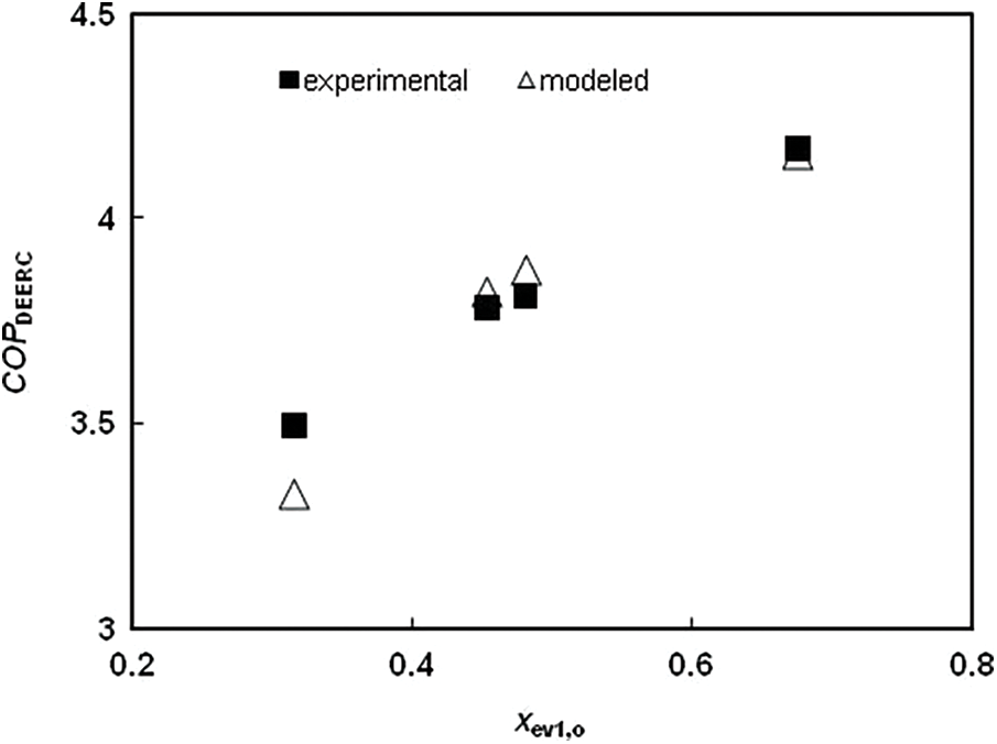
Figure 5: Comparison between the experimental data & the modeled COP
The following results are obtained for the reference operating temperatures, which are set at: TC = 35°C, Tev1 = 0°C and Tev2 = −20°C and a drop pressure in the suction nozzle ΔP = 5 kPa.
4.2 Influence of the Nature of the Fluid
For a degree of sub-cooling ΔTC equal to 10°C and an HTR of 0.8, Fig. 6 depicts the effect of an IHX in the DEERC; it shows the entrainment ratio of the ejector and the system COP with & without IHX for the tested environmentally friendly refrigerants. By adding the IHX, the specific refrigeration effect produced at the refrigerating evaporator increases from 4–5 to 4’–5’ for all the refrigerants considered as shown in Fig. 4. However, the mechanical work of the compressor has also increased from 1–2 to 1’–2’ for all refrigerants studied, especially for ammonia. As a result, the DEERC with IHX gives a better performance for all refrigerants tested, with the exception of ammonia, which has a better performance without IHX. This is confirmed by the results of Fig. 7, which represents the variation of the improvement in COP of the DEERC for the refrigerants studied. The Improvement of the COP is 3.03% in the case of the R134a (baseline working fluid). With 5.23%, R1234yf has the best improvement in COP followed by R1234ze with 4.51%, then the isobutane R600a with 3.98%.
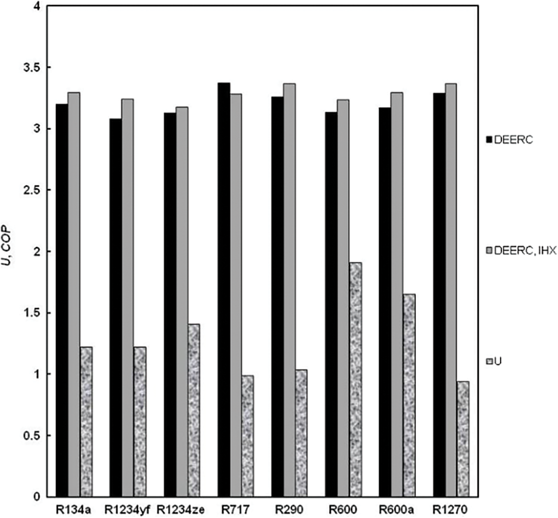
Figure 6: Ejector entrainment ratio and DEERC’s COP with & without IHX for several refrigerants
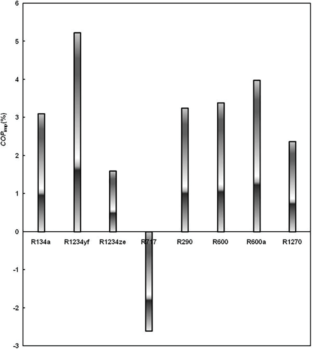
Figure 7: Influence of the nature of the fluid on the DEERC’s COPimp by using an IHX
These results are in agreement with those of Pottker et al. [16] who concluded that refrigerants with high latent heat of vaporization are inclined to profit less from the condenser sub-cooling. Indeed, for a typical air-conditioning system, they reported that because of its lower latent heat of vaporization, the R1234yf (COPimp = 8.4%) fully takes advantage of the condenser sub-cooling compared to R410A (COPimp = 7.0%), R134a (COPimp = 5.9%) and R717 (with COPimp = 2.7%). It should be noted that for lower values of the HTR (for example 0.4), the COPimp values are higher for all the fluids tested, including R717 whose increases in COP become positive.
4.3 Influence of the HTR of the IHX
Fig. 8 represents the variations of the improvement in COP of the DEERC with IHX as a function of the HTR for the baseline fluid R134a and the best fluid R1234yf. The results show that the COPimp of the system decreases as the HTR increases. This is all the more accentuated as the degree of sub-cooling is higher.

Figure 8: Effect of the HTR of the IHX on the DEERC’s COPimp for R134a and R1234yf
4.4 Influence of the Sub-Cooling Degree
Fig. 9 highlights that the improving in the DEERC COP increases with an increase in the degree of sub-cooling ΔTC for both refrigerants (HTR = 0.8). This is all the more accentuated as the HTR of IHX is lower. However, R1234yf presents a much better improvement in COP with the increase of ΔTC.
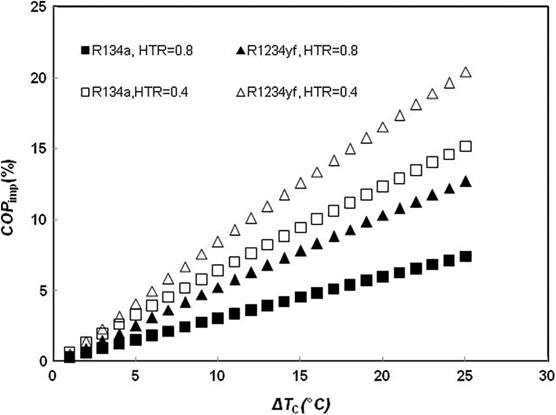
Figure 9: Effect of the sub-cooling degree on the DEERC’s COPimp for R134a and R1234yf
4.5 Influence of the Condensing Temperature
The simulation results also show that the DEERC tends to benefit more from using IHX when the condensing temperature is higher. For refrigerating and freezing temperatures equal to 0°C and −20°C, respectively, an HTR = 0.8 and ΔTC = 10°C, Fig. 10 shows that the COPimp of the DEERC increases with the condensing temperature for the two refrigerants, even if the COPs of the two DEERC systems with and without IHX both decrease when TC increases.

Figure 10: Influence of the condensing temperature on the DEERC’s COPimp for R134a and R1234yf
4.6 Influence of the Evaporating Temperatures
The effect of the difference between the two evaporators (ΔTev = Tev1−Tev2) on the performance enhancement achieved following the insertion of the IHX into the refrigeration system, is investigated by using two methods: the first consists in keeping Tev2 constant and varying Tev1, while in the second, Tev1 is constant and Tev2 is variable. For TC = 35°C, HTR = 0.8 and ΔTC = 10°C, Figs. 11 and 12 present respectively the variations of the COPimp of DEERC as a function of ΔTev for both refrigerants R134a and R1234yf when Tev2 = −20°C and Tev1 = 0°C. These results show that the COPimp of the system decreases slightly in the first case and increases in the second case as ΔTev increases. It can be concluded from these results that the insertion of an IHX is more advantageous at lower refrigerating and freezing temperatures.
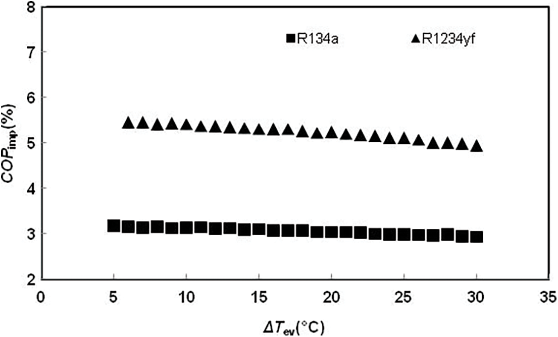
Figure 11: Influence of the refrigerating temperature on the DEERC’s COPimp for R134a and R1234yf (Tev2 = −20°C)

Figure 12: Influence of the freezing temperature on the DEERC’s COPimp for R1234yf and R134a (Tev1 = 0°C)
The effect of an IHX on the DEERC’s performance characteristics has been investigated theoretically. The main conclusions are given below:
• R1234yf and R1234ze are the fluids which benefit the most from the contribution of the IHX. For a degree of sub-cooling value equal to 10°C and an HTR of 0.8, the improvement of the COP is 5.23% for the first fluid and 4.51% for the second. The use of an IHX is not recommended in the case of R717.
• The IHX contribution to increase the DEERC’s performance characteristics is all the more important as the sub-cooling degree is higher and the HTR is lower.
• The effect of the IHX on the DEERC’s performance characteristics is increased by the increase in the temperature of the condenser and the decrease in the temperatures of the two evaporators.
Funding Statement: No specific funding has been received for this study.
Conflicts of Interest: The authors declare that they have no conflicts of interest to report regarding the present study.
References
1. Abdulateef, J. M., Sopian, K., Alghoul, M. A., Sulaiman, M. Y. (2009). Review on solar driven ejector refrigeration technologies. Renewable & Sustainable Energy Reviews, 13(6–7), 1338–1349. DOI 10.1016/j.rser.2008.08.012. [Google Scholar] [CrossRef]
2. Park, C., Lee, H., Hwang, Y., Radermacher, R. (2015). Recent advances in vapor compression cycle technologies. International Journal of Refrigeration, 60, 118–134. DOI 10.1016/j.ijrefrig.2015.08.005. [Google Scholar] [CrossRef]
3. Elbel, S., Lawrence, N. (2016). Review of recent developments in advanced ejector technology. International Journal of Refrigeration, 62, 1–18. DOI 10.1016/j.ijrefrig.2015.10.031. [Google Scholar] [CrossRef]
4. Boumaraf, L., Haberschill, P., Lallemand, A. (2014). Investigation of a novel ejector expansion refrigeration system using the working fluid R134a and its potential substitute R1234yf. International Journal of Refrigeration, 45, 148–159. DOI 10.1016/j.ijrefrig.2014.05.021. [Google Scholar] [CrossRef]
5. Hou, W., Wang, L., Yan, J., Li, X., Wang, L. (2017). Simulation on the performance of ejector in a parallel hybrid ejector-based refrigerator-freezer cooling cycle. Energy Conversion & Management, 143, 440–447. DOI 10.1016/j.enconman.2017.04.030. [Google Scholar] [CrossRef]
6. Desai, A. D., Sapali, S. N., Garikipati, P. V. (2011). Development of energy efficient R-134a automotive air conditioning system using internal heat exchanger. Proceedings of the World Congress on Engineering (WCE), vol. III. London, UK. [Google Scholar]
7. Mota-Babiloni, A., Navarro-Esbrí, J., Barragán-Cervera, Á., Molés, F., Peris, B. (2015). Drop-in of an internal heat exchanger in a vapor compression system using R1234ze(E) and R450A as alternatives for R134a. Energy, 90, 1636–1644. DOI 10.1016/j.energy.2015.06.133. [Google Scholar] [CrossRef]
8. Tomasek, M., Radermacher, R. (1995). Analysis of a domestic refrigerator cycle with an ejector. ASHRAE Transactions, 101, 1431–1438. [Google Scholar]
9. Liu, Y., Xin, T., Cao, L., Wan, C., Zhang, M. (2010). Compression-injection hybrid refrigeration cycles in household refrigerators. Applied Thermal Engineering, 30(16), 2442–2447. DOI 10.1016/j.applthermaleng.2010.06.015. [Google Scholar] [CrossRef]
10. Selvaraju, A., Mani, A. (2004). Analysis of a vapour ejector refrigeration system with environment friendly refrigerants. International Journal of Thermal Sciences, 43(9), 915–921. DOI 10.1016/j.ijthermalsci.2003.12.005. [Google Scholar] [CrossRef]
11. Garcia, J. C. S., Berana, M. S. (2017). Theoretical evaluation of the effect of internal heat exchanger in standard vapor compression and compressor-driven ejector refrigeration systems. Proceedings of the World Congress on Engineering (WCE), vol. 2. London, UK. [Google Scholar]
12. Joseph, D. D., Yang, B. H. (2010). Friction factor correlations for laminar, transition and turbulent flow in smooth pipes. Physica D: Nonlinear Phenomena, 239(14), 1318–1328. DOI 10.1016/j.physd.2009.09.026. [Google Scholar] [CrossRef]
13. Brunin, O., Feidt, M., Hivet, B. (1997). Comparison of the working domains of some compression heat pumps and compression absorption heat pump. International Journal of Refrigeration, 20(5), 308–318. DOI 10.1016/S0140-7007(97)00025-X. [Google Scholar] [CrossRef]
14. Nehdi, E., Kairouani, T., Bouzaina, M. (2007). Performance analysis of the vapor compression cycle using ejector as an expander. International Journal of Energy Research, 31(4), 364–375. DOI 10.1002/(ISSN)1099-114X. [Google Scholar] [CrossRef]
15. Lee, W. H., Kim, Y. J., Kim, M. S., Cho, K. S. (2000). Experimental study on the performance of dual evaporator refrigeration system with an ejector. International Refrigeration and Air Conditioning Conference, USA, Purdue University. [Google Scholar]
16. Pottker, G., Hrnjak, P. (2014). Effect of the condenser sub-cooling on the performance of vapor compression systems. International Journal of Refrigeration, 60, 156–164. DOI 10.1016/j.ijrefrig.2014.11.003. [Google Scholar] [CrossRef]
Cite This Article
 Copyright © 2023 The Author(s). Published by Tech Science Press.
This work is licensed under a Creative Commons Attribution 4.0 International License , which permits unrestricted use, distribution, and reproduction in any medium, provided the original work is properly cited.
 Downloads
 Citation Tools