
 Submit a Paper
 Propose a Special lssue
 Open Access
ARTICLE

Numerical Simulation of Dust Removal in the Cyclone Collector of a Straw Crusher Based on a Discrete Phase Model
1 State Key Laboratory of Mining Response and Disaster Prevention and Control in Deep Coal Mine, Anhui University of Science and Technology, Huainan, 232001, China
2 School of Mechanical Engineering, Anhui University of Science and Technology, Huainan, 232001, China
* Corresponding Author: Chang Su. Email:
Fluid Dynamics & Materials Processing 2023, 19(5), 1143-1157. https://doi.org/10.32604/fdmp.2022.022496
Received 13 March 2022; Accepted 13 July 2022; Issue published 30 November 2022
 View Full Text
 Download PDF
Abstract
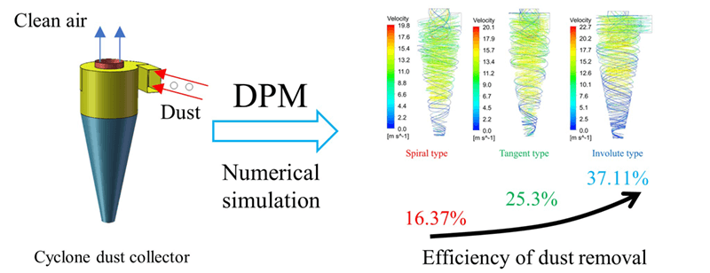
The cyclone dust collector is an important subsystem of straw crushers used in agriculture. In the present study, a new type of dust collector with involute morphology is proposed to obtain better dust removal efficiency with respect to that of classical tangential and spiral dust collectors. A discrete phase model (DPM) method is used in synergy with a turbulence model, and the SIMPLE algorithm to simulate the flow field inside the dust collector and the related particle dynamics. It is shown that the internal flow field features a primary swirl, a secondary swirl and blockage effects. Moreover, for the involute dust collector, the tangential velocity in the initial stage and the pressure in the high-pressure area are larger than those obtained for the classical types. The dust removal efficiency is 37.11%, 25.3%, and 16.37% for the involute type dust collector, the tangential type and the spiral type, respectively.Graphic Abstract
Keywords
Nomenclature
| | Time-averaged velocity |
| | Position |
| | Time-averaged pressure |
| | Fluid kinematic viscosity |
| | Reynolds stresses tensor |
| | Fluid density |
| | Instantaneous velocity |
| | Turbulent kinetic energy |
| | Turbulent kinetic energy dissipation rate |
| | Gravitational acceleration |
| | Particle velocity |
| | Drag force |
| | Particle Reynolds number |
| | Dynamic viscosity |
| | Particle diameter |
| | Particle density |
| | Drag coefficient |
With the rapid development of industrialization, machinery and equipment have been widely used in agriculture. In the course of agricultural production, crops such as corn and wheat produce a large amount of straw, which needs to be crushed by a crusher for further processing and utilization [1]. However, crop stalks generate dust during the crushing process. These dusts not only accelerate the wear of the crusher but also take varied toll on light, air quality, crushing efficiency, and the health of workers once they fly into the air. The cyclone dust collector is a kind of dust-removal equipment with advantages of simple structure, no internal rotating parts, low cost, small area, and easy operation and maintenance; it is suitable for high-temperature, high-pressure, and high-concentration process gas [2]. Cyclone dust collectors are widely used in industrial fields, such as thermal power generation, petroleum, chemical industry, cement, steel, and metallurgy [3–5]. Besides, they are used in straw crushers, which could collect the straw particles produced by the shredder. Cyclone dust collectors could be divided into tangent, involute, and spiral types. At present, the types of dust collectors on the crusher are tangent and spiral types, but their dust-removal and capture efficiencies during the pulverization process remain to be improved.
Many studies on cyclone dust collectors have been carried out. For instance, Zhang et al. [6] analyzed the pressure and distribution of dust particles in the device under different working conditions and structures. They also studied the relationship between the structure of the cyclone dust collector and the dust collection efficiency. By increasing the number of the internal blades of the cyclone, the dust collection efficiency was improved. Dust particles of 5–10 μm could achieve collection efficiency of more than 90% by increasing the flow rate, whereas the collection efficiency of dust with a particle size of 1–5 μm was below 50%. Computational fluid dynamics (CFD) is one of the key components of the numerical simulation methods [7–9]. Lv et al. [10] used computational fluid dynamics (CFD) technology to simulate the internal flow field of the cyclone. The speed, temperature, and particle size at the entrance of the separator were compared and analyzed in three different working conditions, and finally, the separation efficiency and performance were obtained. On the basis of CFD technology, Xi et al. [11] carried out a gas–solid two-phase numerical calculation of the internal flow field of the dust collector; pointed out the system defects; and explored the cylinder diameter’s structure of the cyclone dust collector, cylinder length, and air inlet cross-sectional area. The effects of size changes on the dust-removal efficiency, the original structure, and the stability and efficiency of the system were optimized on the basis of the calculation results. Gopalakrishnan et al. [12] used Euler–Lagrange method to analyze the gas–solid two-phase flow in the axial inlet cyclone, the movement trajectory of the particles, and the influence of the particle density on the uniform and variable inlet particle distribution. The simulation results showed that the use of algorithm could effectively simulate the flow field, and the particles could be separated by centrifugation. Omid et al. [13] studied the influence of multiple inlet diversion channels on the performance of cyclone separators. They used the finite volume method and RSM turbulence model to numerically simulate a three-dimensional turbulent flow. The static pressure and the flow field in the cylinder were evenly distributed. Compared with the ordinary cyclone separator, the special design of the inlet guide groove increased the inlet velocity of the cyclone separator body and prevented the airflow entering the cylinder body from moving improperly to the top of the cyclone separator. Wang et al. [14] studied the effect of the type and quantity of the surfactant on the dust-removal rate of the cyclone by adding a surfactant to the aqueous solution, which was atomized into the cyclone dust collector. Such addition could greatly enhance the agglomeration effect, thus improving the collection efficiency, especially for particles around 2 μm. Through a series of experiments, Cho et al. [15] verified a new type of dust-removal system that combines cyclone, wet electrostatic dust collector, and electrostatic spraying technology. Nekrasov, et al. [16] established a mathematical model of the movement of dust particles on the surface of the cylinder and cone of the cyclone dust collector, analyzed the influencing factors of the movement of dust particles on the surface of the cylinder and the cone, and determined the device’s structural parameters and operating parameters. Nowak et al. [17] introduced the structure of the tangential inlet cyclone separator and the influence of its design parameters on the efficiency of dust removal. They analyzed five types of cyclone separators with tangential inlet and showed that the size of the structure parameters of the cyclone separator could affect the range of particles. In addition, the reduction in diameter and pressure affected the efficiency of the cyclone separator. Cristea et al. [18] studied the overall pressure drop and overall collection efficiency of the system. They verified the simulation results through numerical simulations of the strong swirl, turbulence, and heavy dust flow in the large cyclone separator of the cement kiln suspension preheater on the basis of coupled hybrid three-dimensional computational fluid dynamics-dense discrete phase model (CFD-DDPM). Most scholars have optimized the cyclone dust collector or analyzed the influence of different factors on the dust-removal efficiency of the dust collector, but few scholars have studied the dust collector used in the straw crusher in the current agricultural machinery and analyzed the dust-removal effects of different types of dust collector.
Therefore, the CFD-DPM method was used in this paper to numerically simulate the flow field of the cyclone separator of the straw crusher. Comparative analysis of the simulation results found that the existing cyclone dust collector had some defects in its structure and needed to be optimized to improve the dust-removal efficiency. The involute cyclone dust collector adopted the involute line design at the air inlet. The flow of airflow was improved from the structural design for the straw dust to obtain a larger tangential velocity and the dust to be easily captured and collected. The involute cyclone dust collector is of great importance to prolong the service life of straw crusher and protect the health of workers.
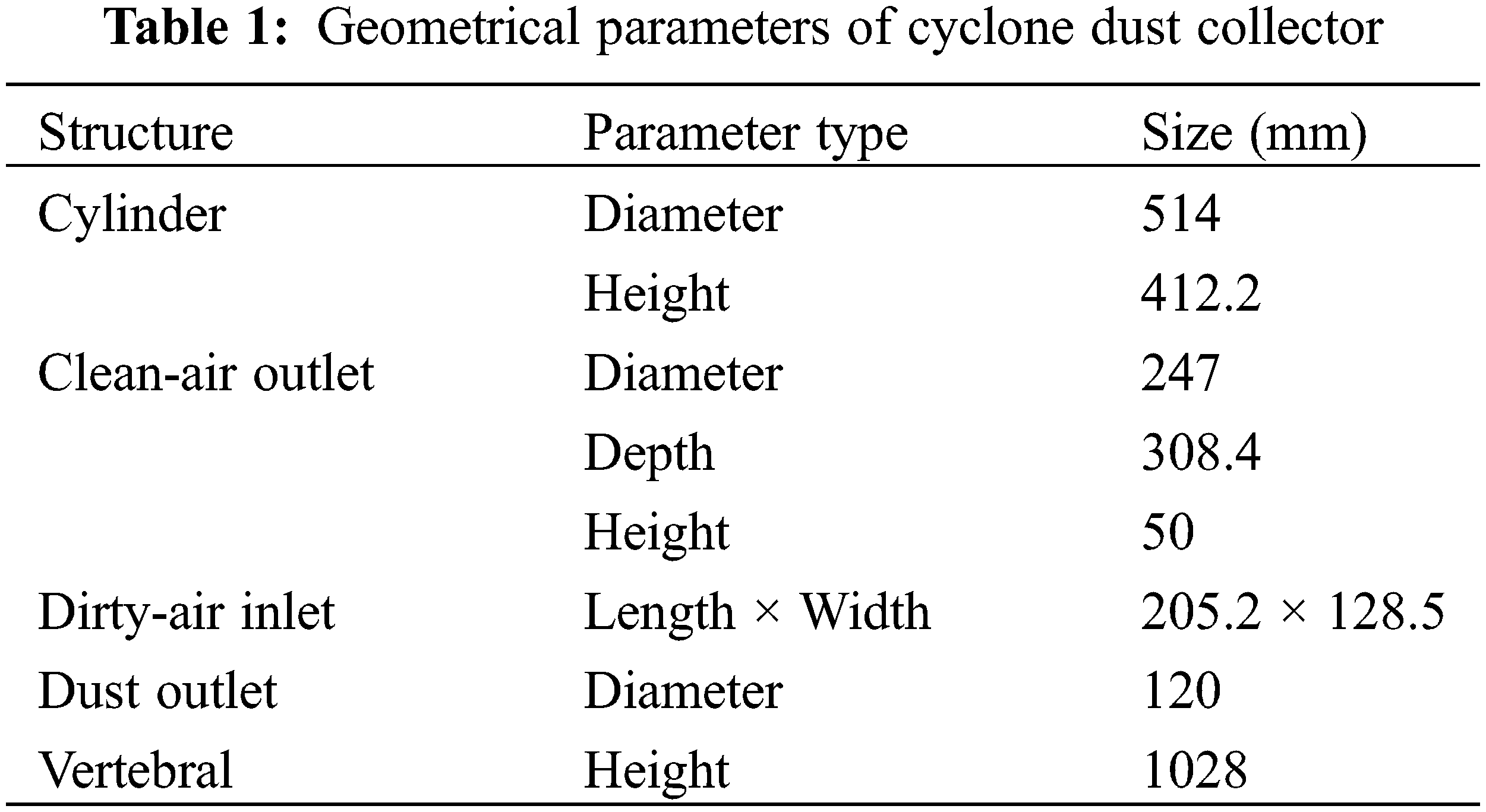
The cyclone dust collector, which consists of a dust outlet, an inlet/outlet pipe, a cone, and a cylinder [19], was installed at the outlet of the straw crusher, as shown in Fig. 1. The specific structural dimensions are shown in Table 1.
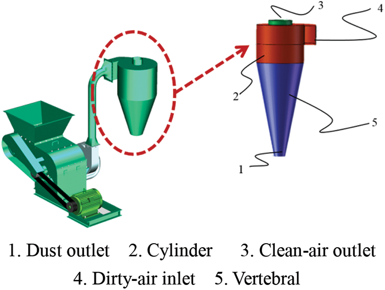
Figure 1: Structure of cyclone dust collector
2.2.1 Governing Equations for Gas Phase
The continuity and Reynolds-averaged Navier-Stokes (RANS) equations for the incompressible isothermal gas phase can be written as [20–22]:
where:
where:
The internal flow field of the cyclone dust collector is complicated, and the flow line is severely curved. Thus, the turbulence model used the Reynolds stress model (RSM) [23–25].
RSM needs to simultaneously solve the following Reynolds stress equation, turbulent kinetic energy k equation, and turbulent kinetic energy dissipation rate ε equation:
Among them,
The empirical constants are
2.2.2 Model Equations for Particle Phase
The trajectory of a dispersed particle can be determined by integrating the force balance equation on the particle in the Lagrange reference frame. The force balance equation of a single dispersed particle can be expressed as follows [27]:
where:
Although the forces acting on particles are quite complex, in general, not all forces are equally important in cyclone separation. When the particle density is much higher than the gas density, the drag force could be considered dominant. The drag force is expressed as follows:
where:
The particle Reynolds number is defined as follows:
The drag coefficient is defined as follows:
The Morsi-Alexander model improves the accuracy in a large range of particle Reynolds number, and it is suitable for simulation under complex working conditions. In the formula,
The SIMPLE algorithm for the pressure-velocity coupling was applied [29,30]. The Presto scheme for discretization of pressure gradient was applied. The QUICK and second-order upwind scheme for momentum and pressure discretization have been applied, respectively. The second order upwind scheme for turbulent kinetic energy and turbulent dissipation rate discretization and the first order upwind scheme for Reynolds stresses discretization were implemented [31,32].
2.4 Building Model and Boundary Conditions
With the new involute cyclone dust collector as an example, the geometric model was established using the 3D modeling software SolidWorks. The mesh quality of the model obtained by filling the fluid domain was poor. Thus, the solid model of the fluid domain was directly established. The model is shown in Fig. 2.
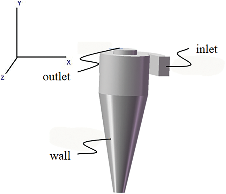
Figure 2: Geometric model of cyclone
2.4.2 Meshing and Boundary Conditions
The numerical simulation adopted the tetrahedral mesh generation method to mesh the computational domain. The grid was tested for irrelevance to improve the accuracy of the calculation results. The results are shown in Fig. 3. When the number of grids exceeds 600,000, the maximum exit velocity is approximately 21.7 m/s. With the increase in the number of grids, the relative error of the maximum velocity does not exceed 0.03%. As the number of grids has a slight effect on the calculation results when it exceeds 600,000, the overall size of the divided grid is 17 mm, the number of cells 586,061, and the number of nodes is 99,965. The 586,061 grids not only could ensure the accuracy of the calculation results but also reduce the calculation time. As shown in Fig. 4, to capture the influence of wall turbulence, the wall mesh was densified. The grid height of the first layer of the boundary layer is 1 mm, the height growth rate is 1.2, and the number of layers is five. The value of y+ is 30–70.
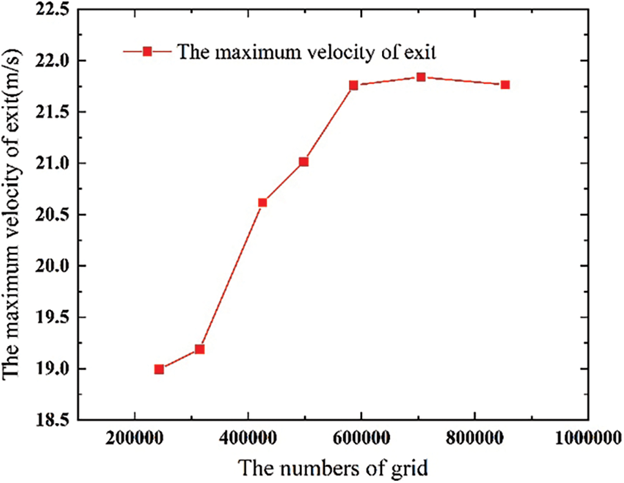
Figure 3: Velocity and grid number
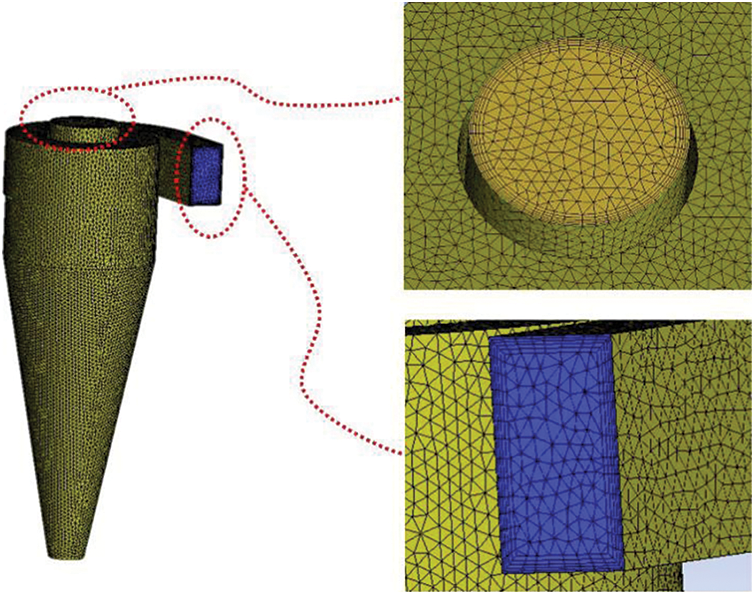
Figure 4: Grid division of cyclone
Inlet boundary: The inlet boundary condition is the velocity inlet. The continuous phase and the discrete phase velocity were set to 10 m/s to simulate the crushing process of the straw crusher. For setting up the DPM model, the tolerance for accuracy control is 1e−7. The maximum number of steps in the tracking parameter is 500,000. The injection type is surface, and the injection is face normal direction. The particle type is inert, and the diameter distribution is uniform. The discrete phase material was set to wood, the total flow rate is 1e−20 kg/s, the particle size was set to 1 μm, and the boundary condition is rebound [6,10].
Outlet boundary: The outlet boundary condition is the pressure outlet. The pressure is a standard atmosphere, and the discrete phase boundary condition is escape.
Wall condition: The boundary condition of the wall is a non-slip wall [33,34], the condition of the discrete phase at the wall of the dust outlet is capture, and the condition of the remaining wall is rebound.
In this paper, steady-state calculation was used. The convergence condition of steady-state calculation is that the residual value tends to be stable and the value of the monitored variable is constant.
2.5 Numerical Simulation Results and Discussion
2.5.1 Analysis of the Flow Field of Dust Collector
According to the axial velocity cloud diagram in Fig. 5, the axial velocity in the cyclone is divided into three areas as a whole. The axial velocity near the cylinder wall and the axis is downward, and the axial velocity in the area between them is upward. According to the streamline diagram of cyclone dust collector in Fig. 6, the airflow enters the cylinder from the inlet to form a swirl, and the airflow moves counterclockwise. When the airflow reaches the bottom of the cylinder, the airflow forms a secondary swirl, and the airflow also moves counterclockwise. A small range of contra-flow could be observed in the area around the axis. The contra-flow area is distributed along the axis, and the contra-flow also moves counterclockwise. The axial velocity of secondary swirl is the largest near the exhaust funnel wall. The radius is equivalent to the exhaust funnel radius, and it gradually decreases from top to bottom in the cone part. The axial velocity distribution at Y = 412.2 mm is shown in Fig. 7. The axial velocity is axisymmetric. The axial velocity of the contact part between the secondary and primary swirl zones and the countercurrent zone is small. The axial velocity on the wall is 0. The axial velocity reaches the maximum velocity in the secondary swirl region. No significant difference could be found in the axial velocity distribution among the three types of dust collectors.
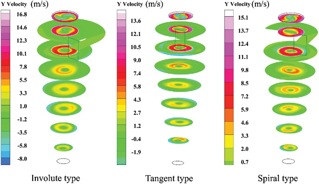
Figure 5: Axial velocity cloud diagram of cyclone dust collector
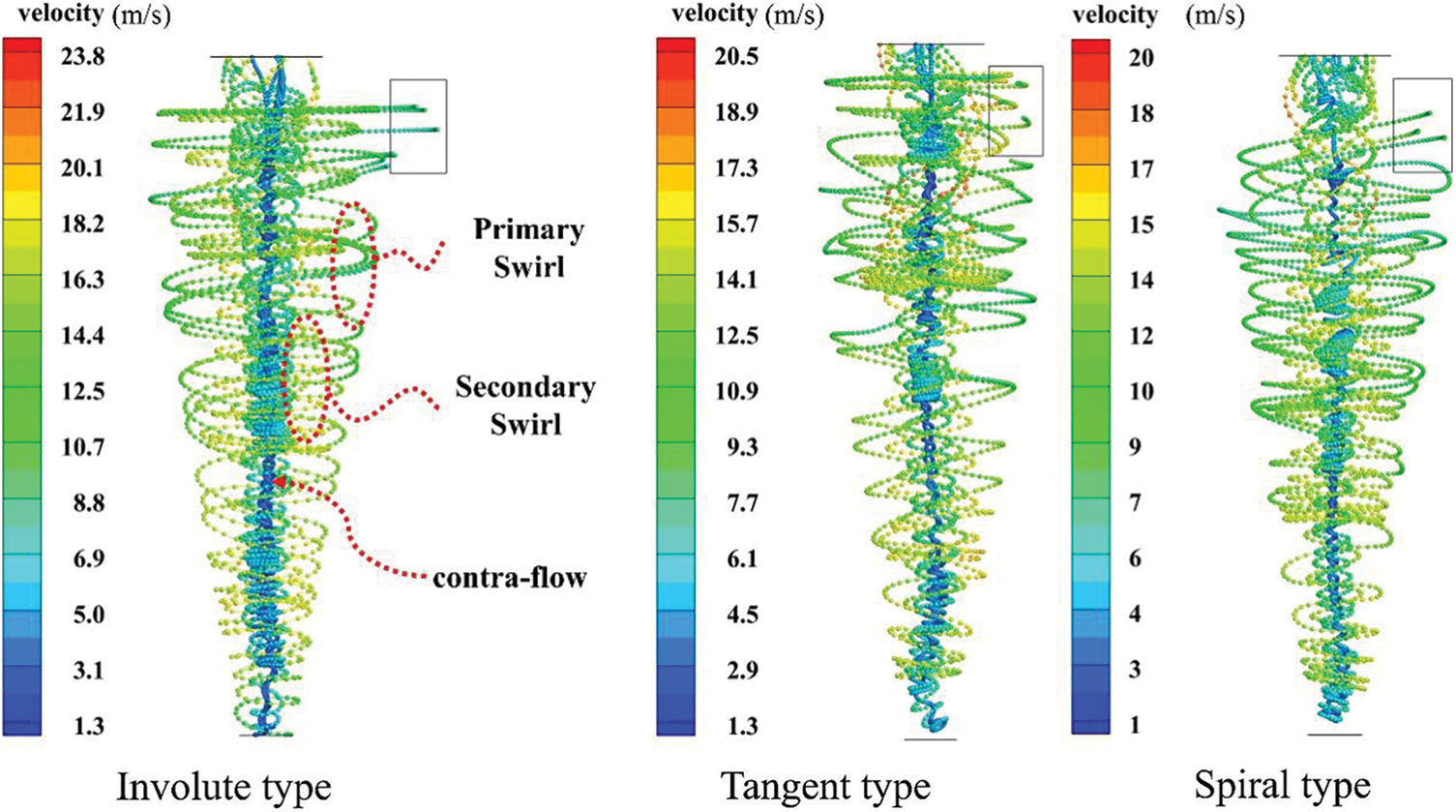
Figure 6: Streamline diagram of cyclone dust collector
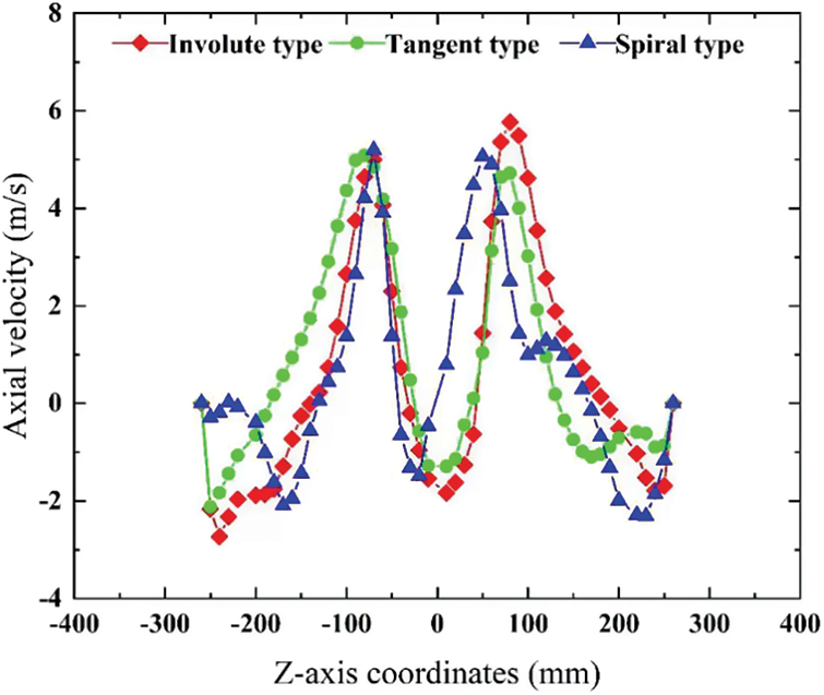
Figure 7: Axial velocity on Y = 412.2 mm cross section
In the cyclone separator, particles and airflow are separated mainly by centrifugal force. The tangential velocity in the flow field of the cyclone separator is the main factor affecting particle settling [35,36]. The greater the tangential velocity is, the greater the centrifugal force received by the particles, and the easier it is for the particles to be separated. The tangential velocity cloud diagram at X = 0 is shown in Fig. 8. The airflow mixed with straw particles enters the cylinder through the air inlet pipe to make a rotating movement. The tangential velocity is the greatest in the area close to the wall of the exhaust cylinder. During the downward movement of the gas, the tangential velocity gradually decreases. The tangential speed of the involute-type dust collector changes slowly, whereas that of the tangent and spiral types change quickly. The tangential velocity of the gas in the involute cone is obviously greater than that of the tangent and spiral types, benefitting the separation of straw particles.
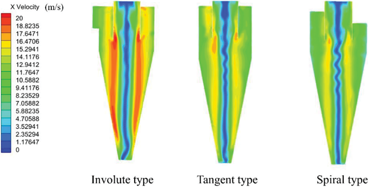
Figure 8: Tangential velocity cloud diagram on X = 0 cross section
At the Y = 412.2 mm section, the tangential velocity distribution curves of the different types of dust collectors are shown in Fig. 9. The tangential velocity increases first in the radial direction from the central axis and then decreases. The speed shows two peaks on both sides of the central axis, and the peaks are close to the wall of the exhaust cylinder. The tangential velocity rapidly decreases to zero near the cylinder. The tangential velocity distribution is approximately symmetrical on the central axis. In the process of accelerating outward from the central axis, slight difference could be found among the tangential speed of the three types of dust collectors. When the tangential velocity reaches the peak value, the tangential velocity of the involute-type dust collector is greater than that of the tangent and spiral types. As the tangential velocity decreases from its peak, not much difference could be observed in the tangential velocity decline of the three types of dust collectors. The overall tangential speed of the involute type is greater than that of the tangent and spiral types, beneficial to the separation of straw particles from the airflow.
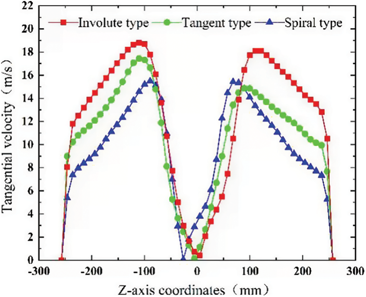
Figure 9: Tangential velocity on Y = 412.2 mm cross section
2.5.2 Pressure Analysis of Dust Collector
The pressure cloud diagram at X = 0 is shown in Fig. 10. The pressure distribution is axisymmetric as a whole. The pressure gradually decreases from the wall along the radius inward, and a negative pressure area is present at the central axis, which is the reason for the contra-flow. The pressure at Y = 412.2 mm on the section is shown in Fig. 11. In the high-pressure area, the pressure of the involute type is higher than that of the other two types. The involute dust collector mainly increases the pressure in the high-pressure area. The pressure curves of the three types of dust collectors in the pressure drop part coincide.
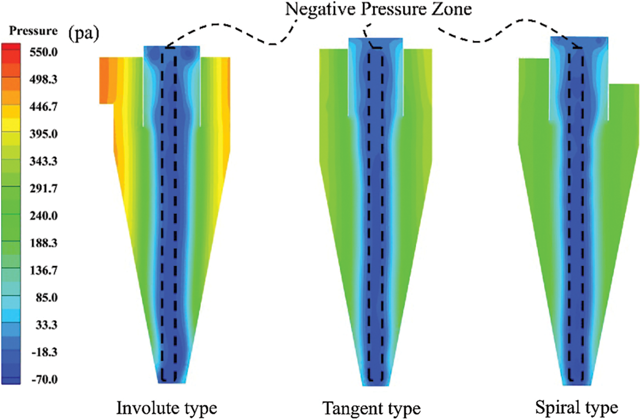
Figure 10: Pressure cloud diagram on X = 0 cross section
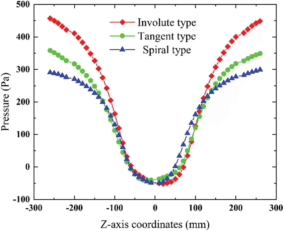
Figure 11: Pressure on Y = 412.2 mm cross section
The wall pressure cloud diagram of three types of cyclone dust collector is shown in Fig. 12. The high-pressure area of the involute type is larger than that of the other two types at the same inlet velocity, indicating that the involute dust collector reduces the pressure loss during the downward movement of the airflow.
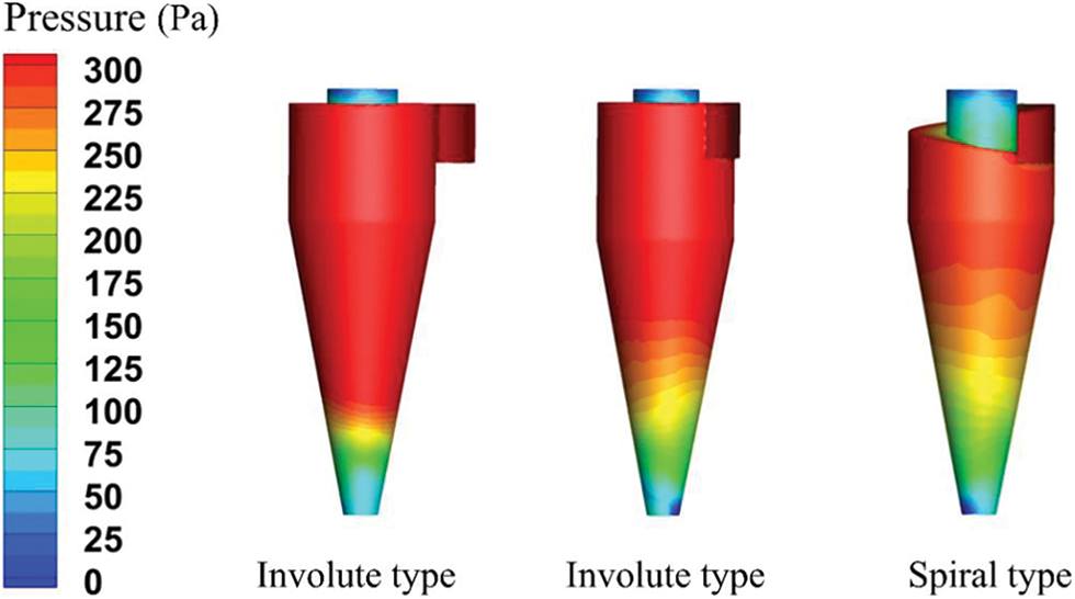
Figure 12: Wall pressure cloud
2.5.3 Analysis of Dust-Removal Efficiency of Dust Collector
By using numerical simulation method, the separation effect of the three types of cyclone dust collectors on straw powder with a particle size of 1 μm was analyzed. The capture rate of the cyclone dust collector was obtained by calculating the number of particles captured. The capture rate was used to demonstrate the dust-removal efficiency, and the simulation results were compared and analyzed.
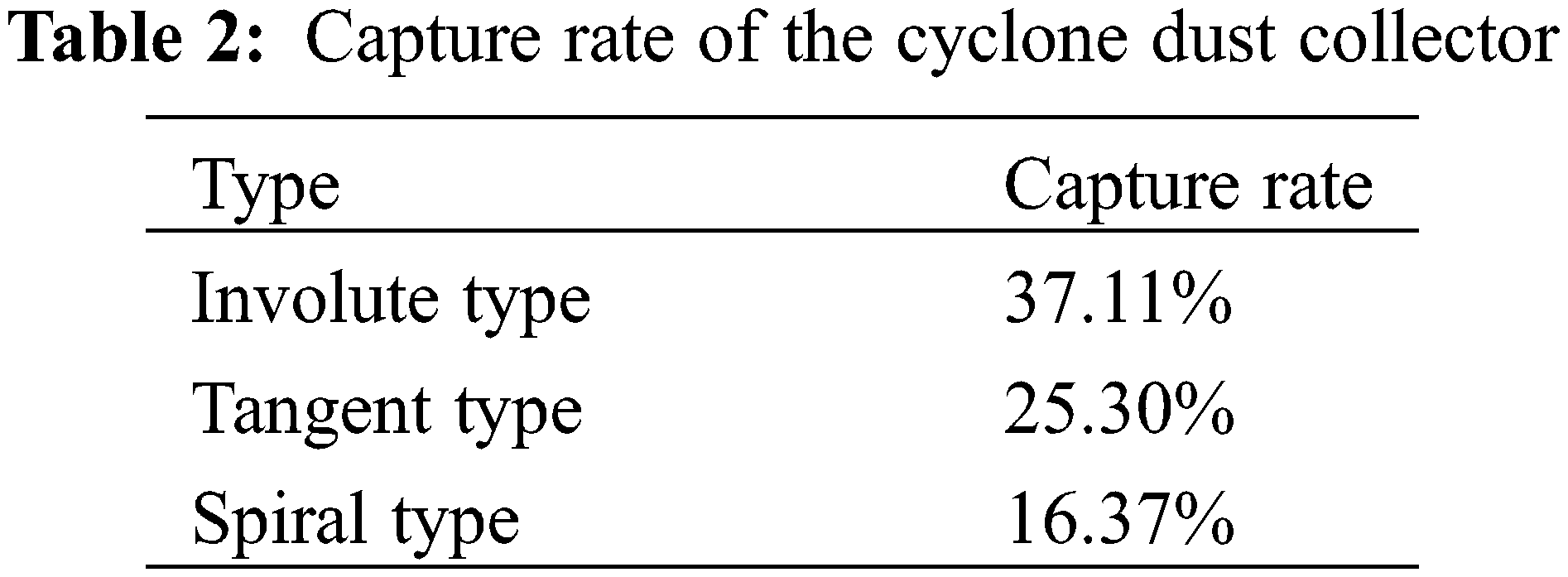
The particle trajectories of the three types of cyclones are shown in Fig. 13. The particles are affected by a swirling flow from the air inlet, and they move counterclockwise downward. The particle velocity near the wall is the smallest, because the particles here receive the largest centrifugal force, and they are pressed on the wall. When the particles reach the bottom of the cone, they are captured. The particles that are not captured move counterclockwise upward and escape from the exhaust port under the influence of the secondary swirl. Due to the action of centrifugal force, some particles cling to the wall when passing through the exhaust funnel, and the speed decreases. The efficiency of the cyclone dust collector is mainly related to the primary swirl. The greater the tangential velocity of the primary swirl is, the greater the centrifugal force on the particles, and the easier for the particles to be captured. As the particle size is evenly distributed, the dust-removal efficiency was calculated by calculating the ratio of the number of captured particles to the number of tracked particles. The particle collection rate of different cyclones is shown in Table 2. The collection rates of the involute, tangent, and spiral types are 37.11%, 25.30%, and 16.37%, respectively. Comparison of these results showed that the new involute-type dust collector has a higher capture rate of straw particles with a particle size of 1 μm than the other types.
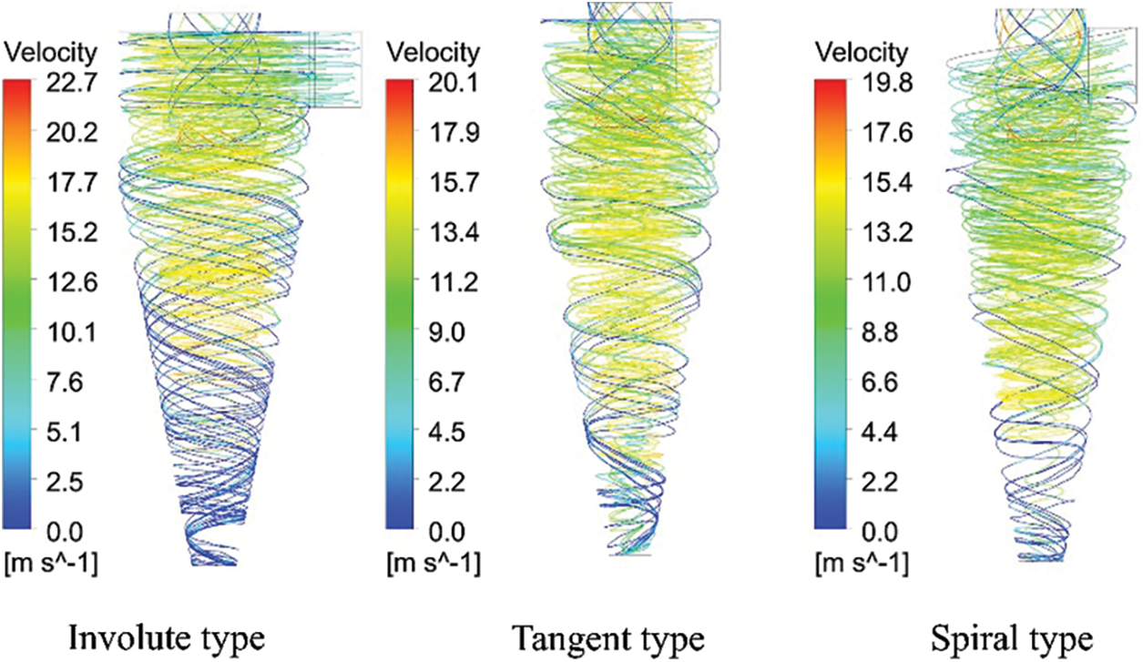
Figure 13: Particle trajectory diagram of the cyclone dust collector
The separation process of straw particles with a particle size range of 1–10 μm was numerically simulated because the straw crusher has a complex working environment and the straw dust has a large particle size range. By comparing the results of numerical simulations, the dust-removal efficiency of different dust collectors with different dust sizes was analyzed, and the result is shown in Fig. 14. The dust-removal efficiency of the dust collector increases with the increase in particle size. The simulation results are close to the experimental results in the reference [37]. The separation efficiency curve of particles is S-shaped. When the particle size exceeds 9 μm, the dust-removal efficiency of the involute type reaches 100%. For straw dust with a particle size range of 1–10 μm, the dust-removal efficiency of the new type of involute dust collector is higher than that of the other types.
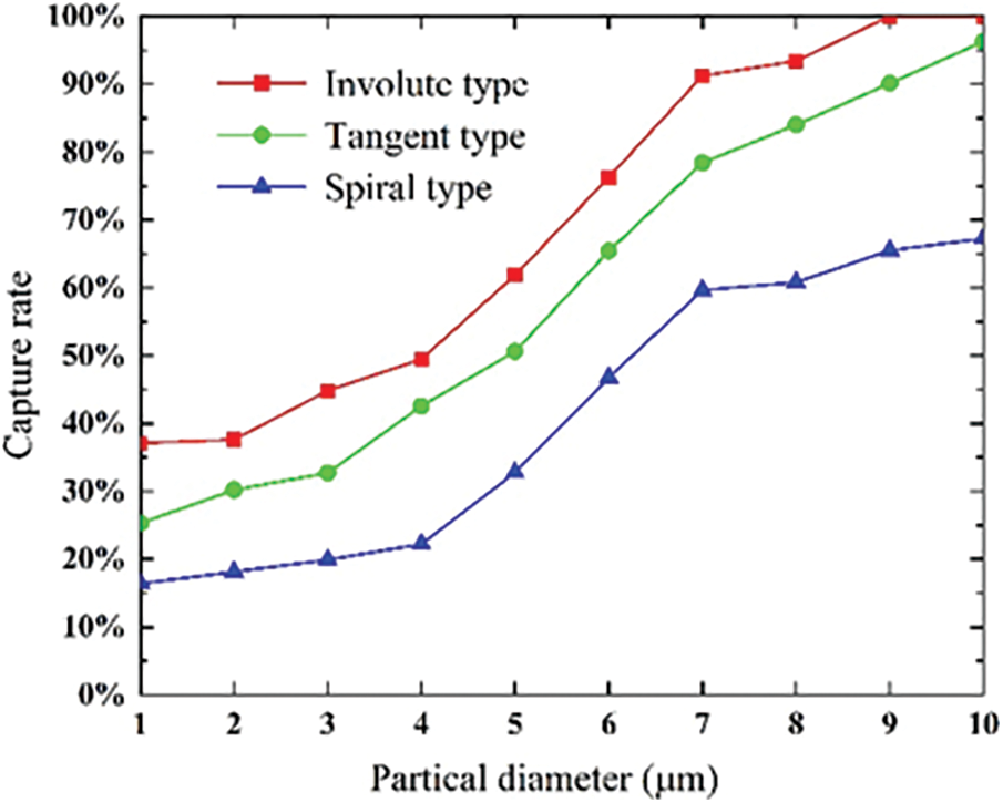
Figure 14: Collection rate of the dust collector for different dust particle sizes
The internal airflow of cyclone dust collector includes a primary swirl, a secondary swirl, and a countercurrent, which are all distributed successively from the cylinder wall to the axis, and the three airflows move counterclockwise. The tangential velocity and axial velocity inside the cylinder are axisymmetrically distributed. Among them, the internal tangential velocity of the involute dust collector is higher than that of the other two types in the increase stage, and no obvious difference in axial velocity could be observed. Meanwhile, the pressure inside the cylinder is in axisymmetric distribution. The involute-type dust collector has pressure in the internal high-pressure area being greater than that of the other two types. In addition, it reduces the pressure loss in the process of primary swirl movement, and the high-pressure area on the wall is greater than that in the other two types. When the particle size of straw is 1 μm and the inlet speed is 10 m/s, the dust-removal efficiencies of the new involute dust collector, the tangent dust collector, and the spiral dust collector are 37.11%, 25.30%, and 16.37%, respectively, showing that the dust-removal efficiency of the involute dust collector is higher than that of the other two types. The dust-removal efficiency of the cyclone is mainly related to the primary swirl. The involute cyclone reduces the pressure loss and improves the tangential speed of the primary swirl. For 1–10 μm straw dust, under any particle size, the dust-removal effect of the involute dust collector is better than that of the other two dust collectors.
Acknowledgement: The authors are very grateful to the editor and anonymous reviewers for their valuable advice.
Funding Statement: The project was supported by the Independent Research Fund of the State Key Laboratory of Mining Response and Disaster Prevention and Control in Deep Coal Mines (No. SKLMRDPC20ZZ06) and the Program in the Youth Elite Support Plan in Universities of Anhui Province (No. gxyq2020013).
Conflicts of Interest: The authors declare that there is no conflict of interests regarding the publication of this paper.
References
1. Wang, Q. F. (2018). Design of key components of straw crusher. Agricultural Engineering, 8(7), 91–94. [Google Scholar]
2. Ray, M. B., Luning, P. E., Hoffmann, A. C., Plomp, A., Beumer, M. (1998). Improving the removal efficiency of industrial-scale cyclones for particles smaller than five micrometre. International Journal of Mineral Processing, 53(1), 39–47. DOI 10.1016/S0301-7516(97)00055-0. [Google Scholar] [CrossRef]
3. Misiulia, D., Andersson, A. G., Lundström, T. S. (2015). Effects of the inlet angle on the flow pattern and pressure drop of a cyclone with helical-roof inlet. Chemical Engineering Research and Design, 102(3), 307–321. DOI 10.1016/j.cherd.2015.06.036. [Google Scholar] [CrossRef]
4. Misiulia, D., Antonyuk, S., Andersson, A. G., Lundström, T. S. (2020). High-efficiency industrial cyclone separator: A CFD study. Powder Technology, 364(8), 943–953. DOI 10.1016/j.powtec.2019.10.064. [Google Scholar] [CrossRef]
5. Yao, Y. G., Huang, W. S., Wu, Y. X., Zhang, Y., Zhang, M. et al. (2021). Effects of the inlet duct length on the flow field and performance of a cyclone separator with a contracted inlet duct. Powder Technology, 393(11), 12–22. [Google Scholar]
6. Zhang, C. Y., Zhang, X. (2021). Simulation analysis of dust collection efficiency of dust collector under different working conditions. Cement Guide for New Epoch, 2(3), 71–75. [Google Scholar]
7. Said, K., Ouadha, A., Sabeur, A. (2022). Turbulent double-diffusive natural convection and entropy generation within an inclined square cavity. Fluid Dynamics & Materials Processing, 18(6), 1619–1629. DOI 10.32604/fdmp.2022.022220. [Google Scholar] [CrossRef]
8. Fourie, L. F., Square, L. (2020). Determination of a safe distance for atomic hydrogen depositions in hot-wire chemical vapour deposition by means of CFD heat transfer simulations. Fluid Dynamics & Materials Processing, 16(2), 225–235. DOI 10.32604/fdmp.2020.08771. [Google Scholar] [CrossRef]
9. Ju, P., Li, M., Wang, J. (2022). Review of research advances in CFD techniques for the simulation of urban wind environments. Fluid Dynamics & Materials Processing, 18(2), 449–462. DOI 10.32604/fdmp.2022.018035. [Google Scholar] [CrossRef]
10. Lv, C. T., Yang, D. (2021). Numerical simulation and analysis of cyclone dust collector. District Heating, 40(2), 63–67. [Google Scholar]
11. Xi, Y., Su, S. Y., Wang, G. J., Liu, X. B., Zhao, Y. H. et al. (2020). Study on gas-solid flow characteristics of cyclone dust collector based on CFD. Mechanical Research & Application, 33(6), 10–13. [Google Scholar]
12. Gopalakrishnan, B., Prakash, K. A. (2020). Numerical study on pressure drop and filtration efficiency of gas-solid flow through axial cyclone separators. International Journal of Advances in Engineering Sciences and Applied Mathematics, 11(4), 280–287. DOI 10.1007/s12572-020-00259-5. [Google Scholar] [CrossRef]
13. Nassaj, O. R., Toghraie, D., Afrand, M. (2019). Effects of multi inlet guide channels on the performance of a cyclone separator. Powder Technology, 356(4), 353–372. DOI 10.1016/j.powtec.2019.08.038. [Google Scholar] [CrossRef]
14. Wang, C., Zhang, Y., Dong, K., Wang, B., Li, S. et al. (2020). Enhanced collection of fine particles in a cyclone using ultrasonic vapor with surfactants. Advanced Powder Technology, 31(6), 2207–2214. DOI 10.1016/j.apt.2020.03.015. [Google Scholar] [CrossRef]
15. Cho, Y., Kim, S., Min, K. J., Kim, M. (2018). Study on PM removal in electrostatic spray technology and combined wet electric cyclone separator. The Korean Society of Mechanical Engineers, 2018, 825–828. [Google Scholar]
16. Nekrasov, A. V., Romanyuk, E. V., Kargashilov, D. V. (2017). Mathematical model for the motion of precipitated dust particles in a high-efficiency cyclone dust collector for explosion-hazardous production. Chemical and Petroleum Engineering, 53(3–4), 190–194. DOI 10.1007/s10556-017-0320-z. [Google Scholar] [CrossRef]
17. Nowak, K., Bukowska, M. (2019). Influence of cyclone construction parameters on the efficiency of dust removal. IOP Conference Series: Materials Science and Engineering, 603(5), 052096. [Google Scholar]
18. Cristea, E. D., Conti, P. (2016). Coupled 3-D CFD-DDPM numerical simulation of turbulent swirling gas-particle flow within cyclone suspension preheater of cement kilns. ASME Heat Transfer, Fluids Engineering, & Nanochannels, Microchannels, & Minichannels Conferences, pp. 12. Washington DC. [Google Scholar]
19. Wang, L. P. (2010). Research of design theory for composite starw grinder (Master Thesis). Northeast Forestry University, China. [Google Scholar]
20. Safikhani, H., Zamani, J., Musa, M. (2018). Numerical study of flow field in new design cyclone separators with one, two and three tangential inlets. Advanced Powder Technology, 29(3), 611–622. DOI 10.1016/j.apt.2017.12.002. [Google Scholar] [CrossRef]
21. Safikhani, H., Akhavan-Behabadi, M. A., Shams, M., Rahimyan, M. H. (2010). Numerical simulation of flow field in three types of standard cyclone separators. Advanced Powder Technology, 21(4), 435–442. DOI 10.1016/j.apt.2010.01.002. [Google Scholar] [CrossRef]
22. Shukla, S. K., Shukla, P., Ghosh, P. (2011). Evaluation of numerical schemes using different simulation methods for the continuous phase modeling of cyclone separators. Engineering Applications of Computational Fluid Mechanics, 5(2), 235–246. DOI 10.1080/19942060.2011.11015367. [Google Scholar] [CrossRef]
23. El-Emam, M. A., Zhou, L., Shi, W. D., Chen, H. (2021). Performance evaluation of standard cyclone separators by using CFD-DEM simulation with realistic bio-particulate matter. Powder Technology, 385, 357–374. DOI 10.1016/j.powtec.2021.03.006. [Google Scholar] [CrossRef]
24. Shaaban, S. (2011). Numerical optimization and experimental investigation of the aerodynamic performance of a three-stage gas-solid separator. Chemical Engineering Research & Design, 89(1), 29–38. DOI 10.1016/j.cherd.2010.04.008. [Google Scholar] [CrossRef]
25. Pandey, S., Brar, L. S. (2022). On the performance of cyclone separators with different shapes of the conical section using CFD. Powder Technology, 407(2), 117629. DOI 10.1016/j.powtec.2022.117629. [Google Scholar] [CrossRef]
26. Yi, L., Wang, C. X. (2006). Numerical simulation of two-phase flow field in spiral cyclone separator. Applied Mathematics and Mechanics, 27(2), 223–229. [Google Scholar]
27. Le, K., Yoon, J. Y. (2020). Numerical investigation on the performance and flow pattern of two novel innovative designs of four-inlet cyclone separator. Chemical Engineering and Processing, 150, 107867. DOI 10.1016/j.cep.2020.107867. [Google Scholar] [CrossRef]
28. Morsi, S. A., Alexander, A. J. (1972). An investigation of particle trajectories in two-phase flow systems. Journal of Fluid Mechanics, 55(2), 193–208. DOI 10.1017/S0022112072001806. [Google Scholar] [CrossRef]
29. van Doormaal, J. P., Raithby, G. D. (1984). Enhancements of the simple method for predicting incompressible fluid flows. Numerical Heat Transfer Applications, 7(2), 147–163. [Google Scholar]
30. Song, J. L., Kharoua, N., Khezzar, L., Alshehhi, M. (2021). Numerical simulation of turbulent swirling pipe flow with an internal conical bluff body. Fluid Dynamics & Materials Processing, 17(2), 455–470. DOI 10.32604/fdmp.2021.014370. [Google Scholar] [CrossRef]
31. Ali, S., Irfan, K. (2017). Numerical prediction of short-cut flows in gas-solid reverse flow cyclone separators. Chemical Industry and Chemical Engineering Quarterly, 23(4), 483–493. DOI 10.2298/CICEQ161009002S. [Google Scholar] [CrossRef]
32. Nejad, J. V. N. N., Kheradmand, S. (2022). The effect of arrangement in multi-cyclone filters on performance and the uniformity of fluid and particle flow distribution. Powder Technology, 399, 117191. DOI 10.1016/j.powtec.2022.117191. [Google Scholar] [CrossRef]
33. Jiang, L., Liu, P., Zhang, Y., Yang, X., Wang, H. et al. (2019). Design boundary layer structure for improving the particle separation performance of a hydrocyclone. Powder Technology, 350(5), 1–14. DOI 10.1016/j.powtec.2019.03.026. [Google Scholar] [CrossRef]
34. Kosaki, Y., Chono, S. (2017). Time characteristics of dust collection and particle classification performance of a cyclone. Powder Technology, 305, 602–608. DOI 10.1016/j.powtec.2016.10.040. [Google Scholar] [CrossRef]
35. Qi, M., Wang, B. T., Chen, Q. G., Fu, Q. Q. (2021). Numerical analysis of performance of cyclone separator with recovery of waste heat. Journal of Drainage and Irrigation Machinery Engineering, 39(4), 386–391. [Google Scholar]
36. Zhao, Y., Chen, J. Y., Cao, M. Q., Ye, S., Kong, L. S. (2021). Performance of the cyclone separator with variable inlet area. Acta Petrolei Sinica, 37(5), 1031–1039. [Google Scholar]
37. Noh, S. Y., Heo, J. E., Woo, S. H., Kim, S. J., Ock, M. H. et al. (2018). Performance improvement of a cyclone separator using multiple subsidiary cyclones. Powder Technology, 338, 145–152. DOI 10.1016/j.powtec.2018.07.015. [Google Scholar] [CrossRef]
Cite This Article
 Copyright © 2023 The Author(s). Published by Tech Science Press.
This work is licensed under a Creative Commons Attribution 4.0 International License , which permits unrestricted use, distribution, and reproduction in any medium, provided the original work is properly cited.
 Downloads
 Citation Tools