
 Submit a Paper
 Propose a Special lssue
 Open Access
ARTICLE

A Strategy to Control the Turbocharger Energy of a Diesel Engine at Different Altitudes
1 National Key Laboratory of Diesel Engine Turbocharging Technology, China North Engine Research Institute, Tianjin, 300400, China
2 School of Mechanical Engineering, Tianjin University, Tianjin, 300073, China
3 Key Laboratory for Power Machinery and Engineering of Ministry of Education, Shanghai Jiao Tong University, Shanghai, 200240, China
* Corresponding Author: Lei Shi. Email:
Fluid Dynamics & Materials Processing 2023, 19(4), 959-975. https://doi.org/10.32604/fdmp.2023.023687
Received 09 May 2022; Accepted 18 July 2022; Issue published 02 November 2022
 View Full Text
 Download PDF
Abstract
Power deterioration is a major problem for diesel engines operating at high altitudes. This problem stems from the limited availability of turbocharger energy, which is not enough to increase the boost pressure to the required level. In this study, a control strategy is introduced in order to achieve engine power recovery at different altitudes. It is shown that as the altitude increases from 0 to 4500 m, the required boost pressure ratio increases from 2.4 to 4.3. The needed turbocharger energy should be increased accordingly by 240%, and the TCC (turbine characterization coefficient) should be adjusted within wide ranges. A 12% decrease in the TCC can lead to a rise of the intake air pressure, which can compensate the pressure decrease due to a 1000 m altitude increase. The fluctuation range of boost pressure was within 14.5 kPa for variations in altitude from 0 to 4500 m.Keywords
Notations
| A | Equivalent turbine area, cm2 |
| K | Adiabatic exponent |
| | Mass flow rate, kg s−1 |
| P | Pressure, kPa |
| | Gas constant, J K−1 |
| T | Temperature, K |
| D | Diameter, cm |
| N | Number of cylinder |
| Subscripts | |
| 0, 1, 2... | States |
| 00, 10, 20... | Total states |
| e | Exhaust gas |
| T | Turbine |
| Abbreviations | |
| TCC | Turbine characterization coefficient |
| VGT | Variable geometry turbocharger |
Diesel engine is the main power of engineering machineries and heavy vehicles, and has the request to improve the power and emission performance [1–3]. Plateaus are distributed widely all over the world, and engineering machineries and heavy vehicles often need to operate at plateaus with variable altitudes. It is well recognized that altitudes have significant effects on the performances of engines [4]. As altitude increases, the density and pressure of atmosphere decrease rapidly, leading to less air flows into engine cylinder. As a consequence, the performances of the engine will significantly deteriorate and may not meet the requirements of vehicle operation at different altitudes [5,6]. Therefore, it is necessary to improve the performances of engines under high altitudes.
Many studies regarding the influences of altitude on the performances of diesel engines were conducted by numerical simulations and thermodynamic analyses. For example, Dennis et al. [7] compared the performances of turbocharged diesel engines at various altitudes, and then adopted part-load curves obtained on plains to predict the performances of engines at various altitudes. Ángel et al. [8] evaluated the effects of altitudes on the engines’ performances, emissions, and thermodynamic diagnoses under real-world driving conditions. Zhu et al. [9] adopted a genetic algorithm to optimize fuel injection parameters of diesel engines, resulting in the enhanced performances of engines on plateaus. Humans et al. [10] and Chaffin et al. [11] analyzed the influences of different altitudes on emissions characteristics for a naturally aspirated diesel engine and a turbocharged diesel engine, respectively. Zhang et al. [12,13] studied the control strategy of two-stage turbocharging system for different altitude. The above studies all suggest that altitudes have significant effects on the performances of diesel engines.
Turbocharging technology is an effective method to improve the air supply to diesel engines, and then to increase the boost pressure and the recovery of the engine power at high altitudes [14]. The available energy to the turbine is the key factor that affects the boost pressure and the power capability of turbine. Normally, turbocharge systems can provides enough turbocharger energy for boost pressure recovery at a fixed altitude, but it is difficult for them to provide optimum turbocharger energy when the operating altitude changes over a wide range [15]. Meanwhile, the demanded energy and the available energy of turbochargers cannot achieve a balance, when the operating condition deviates from the matching point of turbocharge system under variable altitudes. To reduce this imbalance, the turbocharger energy should be regulated according to the equivalent turbine areas at different altitudes [16]. However, the turbocharging system with a fixed equivalent turbine area cannot satisfy the intake air demand under all operating conditions, whether it operates at the low or the high altitudes. Therefore, the control of turbocharger energy needs to be further investigated to achieve high performances of engines at different altitudes.
Studies [17–20] have been conducted to investigate the engine torque recovery at high altitudes. It is found that the increase of the actual boost pressure is the most efficient way to improve the performances of turbocharged diesel engines at high altitudes. The boost pressure can be optimized by using the turbocharging system control method. Zhang et al. [21] adopted the variable geometry turbocharger (VGT) technology to improve the dynamic performances of the engine at different altitudes, and further investigated the control strategies of a VGT system under different operating conditions. Liu et al. [22] numerically compared the performances of a one-stage and a two-stage turbocharged diesel engines at different altitudes. It was found that the two-stage turbocharging system can improve the plateau performances of diesel engines. Shi et al. [23] analyzed the performances of a diesel engine with a two-stage sequential boosting system at different altitudes. The results showed that a good match of the turbocharging system would contribute to a power recovery of 80% even at high altitude (5.5 km). Katrašnik et al. [24] proposed an air management strategy based on the numerical model to carry out the performances optimization of a turbocharged diesel engine. The above numerical simulations or thermodynamics analyses of engines at high altitudes are usually based on the simple turbo model. However, the accuracy of the simple turbo model will drop dramatically when the altitude is more than 4000 m (the corresponding expansion ratio of turbine will always exceed 3.5).
Studies have also shown that a fixed turbocharger cannot meet the intake air demand of engines at different altitudes [25]. For single-stage turbocharging systems operating at high altitudes, the turbocharger tends to be overspeed, and then the efficiency will decrease greatly due to turbo blocks [26–28]. Ghazikhani et al. [29] conducted a series of experiments, to study the intake air flow and soot emissions at different altitudes by changing the opening of the waste-gate valve. Li et al. [30] analyzed the relationships between the matching speed, the pressure ratio distribution, and the plateau adaptability for a two-stage turbocharging system. It was found that the matching point and the required total pressure ratio collectively determine the equivalent turbine area. Yang et al. [31] studied the altitude adaptability of a turbocharged diesel engine based on three limits: the maximum cylinder pressure, turbocharger speed and exhaust temperature.
From the above analyses, the following remarks are drawn: (1) Turbocharger has a remarkable impact on engine torque, it is difficult for the fixed turbine to achieve good performances of engines at both low and high altitudes. (2) The available energy of turbocharger, which is determined by the power capability of turbine, is the critical factor for boosting pressure recovery to maintain engine torque at high altitudes. However, existing studies have seldom cared about the effects of turbine’ power capability on turbocharger energy and pressure boost at different altitudes. As the power capability of turbine is closely correlated to the turbocharger energy, hence, it can be used as a criterion to control the boost pressure at different altitudes. Nevertheless, when the turbocharger energy is designed for the engine at high altitude, it tends to make the in-cylinder pressure easily exceed the limit at low altitude. In contrast, when the turbocharger energy is suitable for the engine at low altitude, it will easily result in combustion deterioration at high altitude due to the insufficient intake air. This study tries to deal with this conflict, and intends to recover boost pressure and improve the engine power at different altitudes. In this paper, the effects of the power capability of turbine on turbocharger energy and engine power are investigated, and a control strategy of turbocharger energy is proposed to keep the boost pressure a constant at different altitudes.
2 Simulation and Experimental Verification
2.1 TCC Model of Turbocharging System
In the matching process of diesel engine and turbocharging system, the turbine is usually abstracted as a nozzle model. There are two types of nozzle models: single-nozzle model and two-nozzle model. The single-nozzle model can provide reasonable results for radial turbines within moderate expansion ratios. However, it will be easily choked when the expansion ratio exceeds 1.9, and then cannot provide accurate results [32]. In fact, the actual expansion ratio of a radial turbine might exceed 3.5 at high altitudes. This suggests that the simple single-nozzle model is inappropriate for turbine matching. To overcome this shortcoming, Payri et al. [33,34] proposed a new turbine model which consists of two nozzles and an intermediate volume. In this model, two expansion processes take place sequentially in the stator and the turbine rotor. It shows a better agreement with the actual expansion process at high expansion ratios. The schematic diagram of the two-nozzle radial turbo model is shown in Fig. 1.
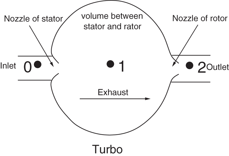
Figure 1: Schematic diagram of the two-nozzle radial turbo model
At high expansion ratios, the two-nozzle turbine model shows high accuracy because it has considered the reaction degree of the turbine. The reaction degree is defined as the ratio of the rotor’s static enthalpy drop to the stage’s total energy conversion, and it can be written as
where,
The working fluid in the turbine can be considered as perfect gas, then the outlet pressure of the stator is calculated as follows:
Assuming a polytropic expansion process for the gas in the turbo model, yields
where,
Substituting Eq. (2) into Eq. (3), yields
From Eq. (3), the polytropic exponent
According to the design rules of radial turbines, the reaction degree is usually set to be 0.5 [28]. Assuming that the gas expands adiabatically in the turbine rotor, then the polytropic exponent equals to the adiabatic exponent
Using the polytropic process hypothesis and considering Eq. (2), we obtain the pressure ratio of the turbine stator as follows:
From Eq. (7), the outlet pressure of the turbine stator and the reaction degree of the turbine can be calculated to determine the expansion ratio of the stator and the turbine rotor.
As suggested by Payri [26,27], the equivalent flow area of the nozzle
where,
In the matching process of turbocharging system, the turbine energy mainly depends on the equivalent area of the turbine. Considering the fact that the demand value of the equivalent area is positively correlated with the displacement of the diesel engine, a dimensionless coefficient named TCC (turbine characterization coefficient) is proposed to replace the equivalent area of the turbine as follows:
where, N is the number of cylinders connected to one turbine, and D is the averaged diameter of the cylinders.
The dimensionless coefficient TCC is appropriate for different engines, as it is associated with the displacement of diesel engine and the evaluation criterion of turbine energy control.
2.2 Engine Simulation and Experimental Verification
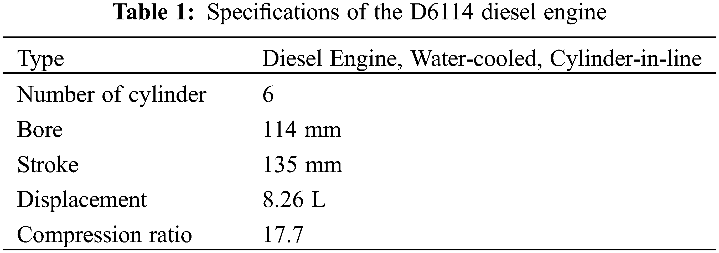
In this subsection, a four-stroke turbocharged diesel engine (model number: D6114), which is applied to engineering machineries and heavy vehicles at 0~4500 m altitudes, is selected for numerical and experimental studies, to analyze the effects of the turbines’ power capability on the turbocharger energy and the engine power at different altitudes. The main parameters of the engine are listed in Table 1. In the following context, the numerical simulation method is firstly introduced, and then is validated by the experiment.
2.2.1 Setup of Engine Simulation
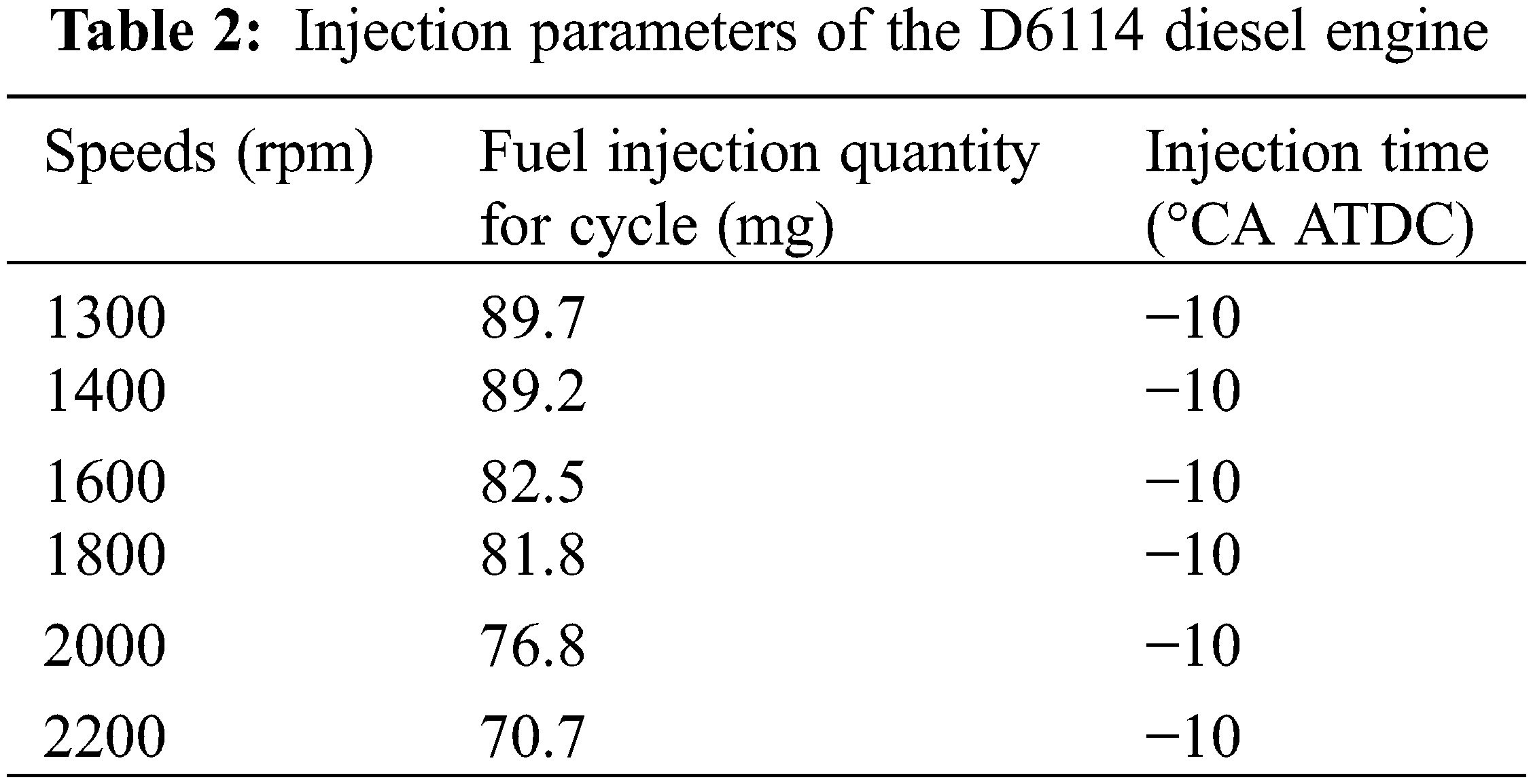
The engine simulation model is established in GT-Power software developed by Gamma Technologies. Fig. 2 shows the simulation model of the turbocharged diesel engine. In this simulation model, the intake and exhaust pipes are modeled by the one-dimensional simplified model. The turbine and the compressor are modeled with the experimental data of the characteristic maps provided by the manufacturer. The DI-Wiebe combustion model, which is reliable for different ambient conditions, is used to predict the combustion processes under different operating conditions. The specific fuel injection parameters are shown in Table 2. In the simulation, the fuel injection pressure of the rated load is fixed at 180 MPa for variable altitudes, and the intake pressure is adjusted according to the real air pressure at different altitudes.
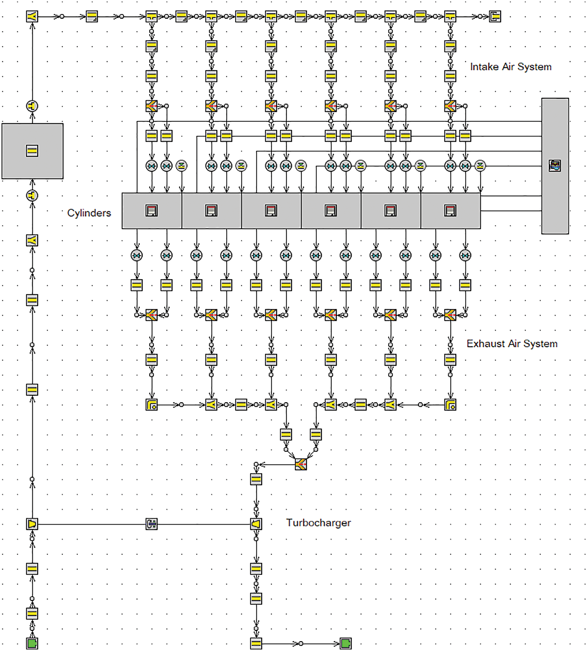
Figure 2: Simulation model of the turbocharged diesel engine
2.2.2 Experimental Verification
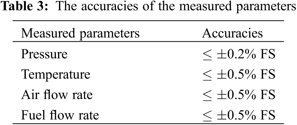
Experiments are carried out to verify the accuracy of the engine model. Fig. 3 illustrates the sketch of the experimental test bench. The 1PH8228-1HF40-0BB2-Z dynamometer from SIEMENS is used to measure the power output of the engine. The RCCS30 transient fuel mass flow meter from ROTA YOKOGAWA is adopted to measure the fuel flow rate. An NI data-acquiring system is used to measure the pressure and temperature, in which the pressure sensors in air path line are the HALO-XQ-WG pressure transmitters, and the temperature sensors are the PT100 thermoelectrical resistances. The measurement accuracies of the parameters are listed in Table 3.
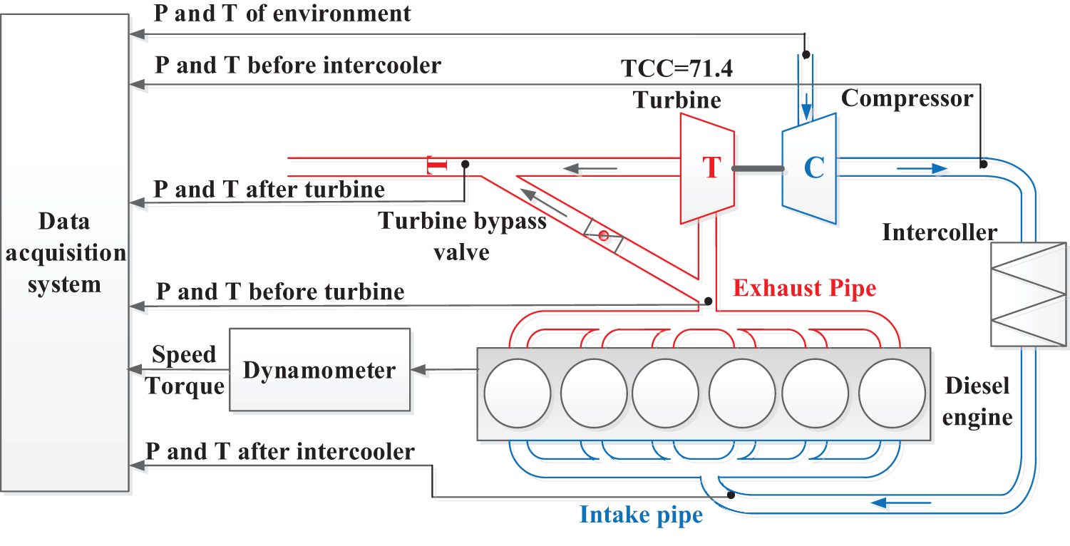
Figure 3: Schematic diagram of test bench
The prediction of the pressure in the cylinder is critical to engine performance simulation. Fig. 4 compares the pressure in the cylinder at different altitudes between the simulation and the test results. It is clear from the figure that the simulation results agree well with the test results for different altitudes, and the maximal error between the simulation and the test results is less than 2.26 bar. Thus, the selected and calibrated combustion model is reliable for combustion simulation at different altitudes.
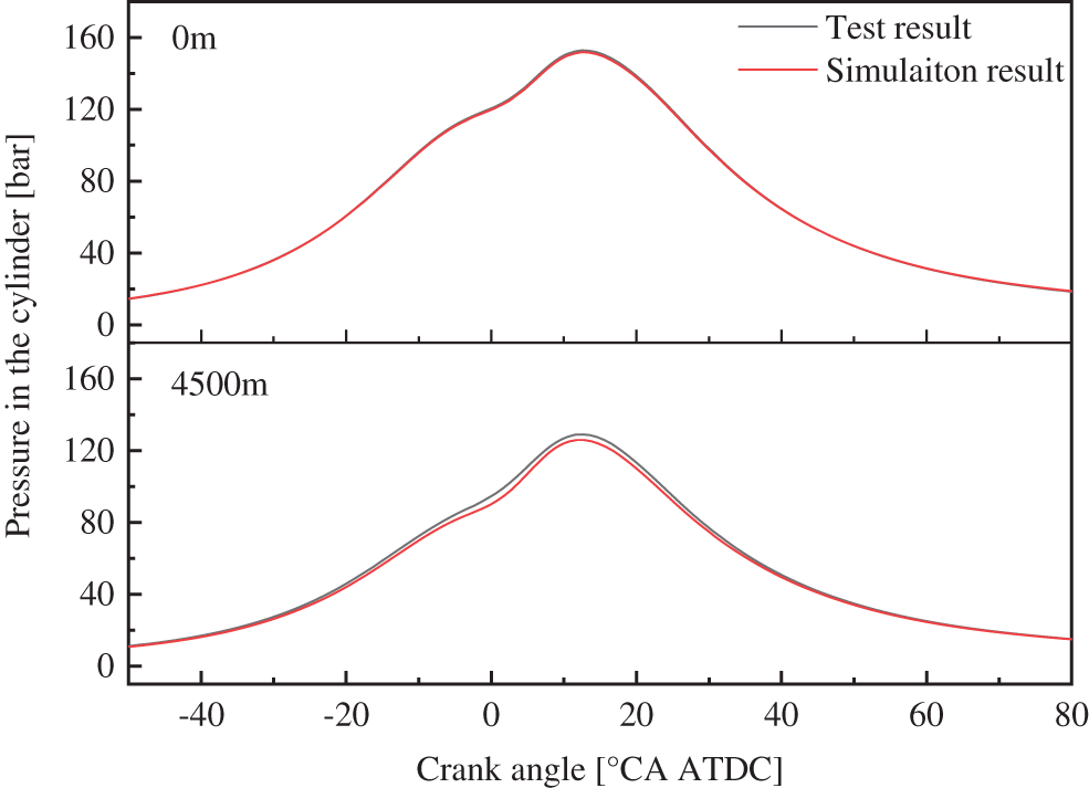
Figure 4: Comparison of the pressure in the cylinder at different altitudes between the simulation and the test results
Fig. 5 shows the relative errors of the main performance parameters between the simulation and the test results. It is found that the relative errors of these main performance parameters are all within 5%. This suggests that the simulation model is reliable and robust. Therefore, the simulation model can be used to study the effects of the turbines’ power capability on turbocharger energy and engine power at different altitudes.
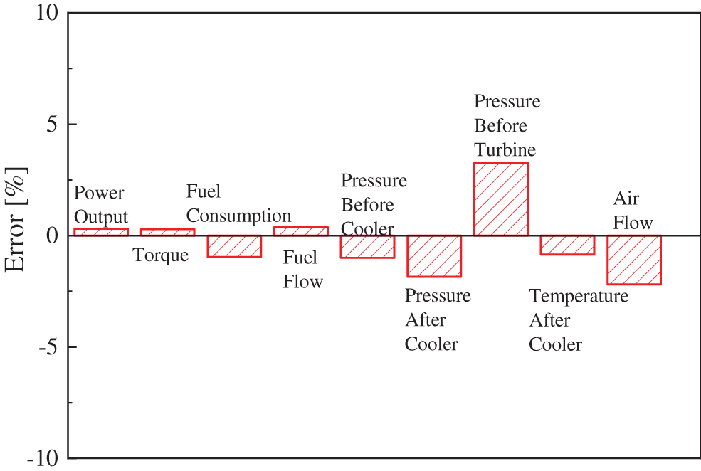
Figure 5: Relative errors between the simulation and the test results
3 Turbocharger Energy Analyses
The power capability of turbine not only determines the expansion ratio, but also dominants the turbocharger energy and then affects the boost pressure. Hence, the effects of the power capability of turbine on the turbocharger energy at different altitudes are analyzed based on the constructed simulation model.
3.1 Requirements of Turbocharger Energy
As the altitude increases, the density and pressure of atmosphere decrease rapidly. The compression energy must be increased to maintain a constant boost pressure and air flows at different altitudes. Fig. 6 shows the required boost pressure and compression energy at different altitudes. The demanded boost pressure ratio increases from 2.4 to 4.3 when the altitude increases from 0 to 4500 m. As the boost pressure increases, the energy provided by turbine should be also improved. Assuming that the compression energy is 100% for the speed of 1000 r/min at the sea level (baseline value), the compression energies under other conditions are all quantified relative to the baseline value. As illustrated in Fig. 6, for the constant speed (1000 r/min), the required compression energy increases to 240% at the altitude of 4500 m. On the other hand, in terms of the constant altitude (0 m), the required compression energy improves to 183% at the speed of 1800 r/min. It is found from the figure that the required compression energy varies dramatically to maintain the demanded boost pressure ratios under different engine speeds and altitudes.
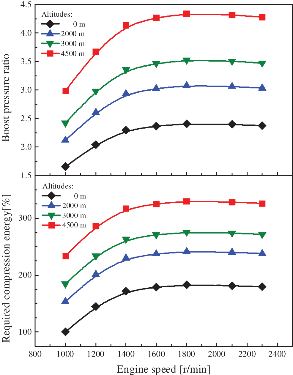
Figure 6: The boost pressure ratio and compression energy requirements at different altitudes
3.2 Turbocharger Energy vs. Turbine Power Capability
The turbocharger energy is mainly determined by the power capability of turbine. In order to use the power capability of turbines to control the turbocharger energy, the effect of the power capability of turbine on the turbocharger energy should be analyzed.
Fig. 7 shows the effects of the TCC on the expansion ratio and the turbocharger energy at different altitudes. It is clear from the figure that for a fixed TCC, the expansion ratio and the turbocharger energy increase with the altitude. Increasing TCC yields higher turbocharger energy and expansion ratio, which can provide sufficient turbocharger energy and is suitable for engines operating at high altitudes. In contrast, reducing TCC results in a lower expansion ratio, which is able to avoid excess boost pressure and is appropriate for engines operating at low altitudes. Consequently, a fixed TCC cannot provide acceptable turbocharger energy for different altitudes. The turbocharger energy should be changed within a wide range to provide sufficient energy for boost recovery. As the altitude increases from 0 to 4500 m, the TCC should be increased to satisfy the required energy.
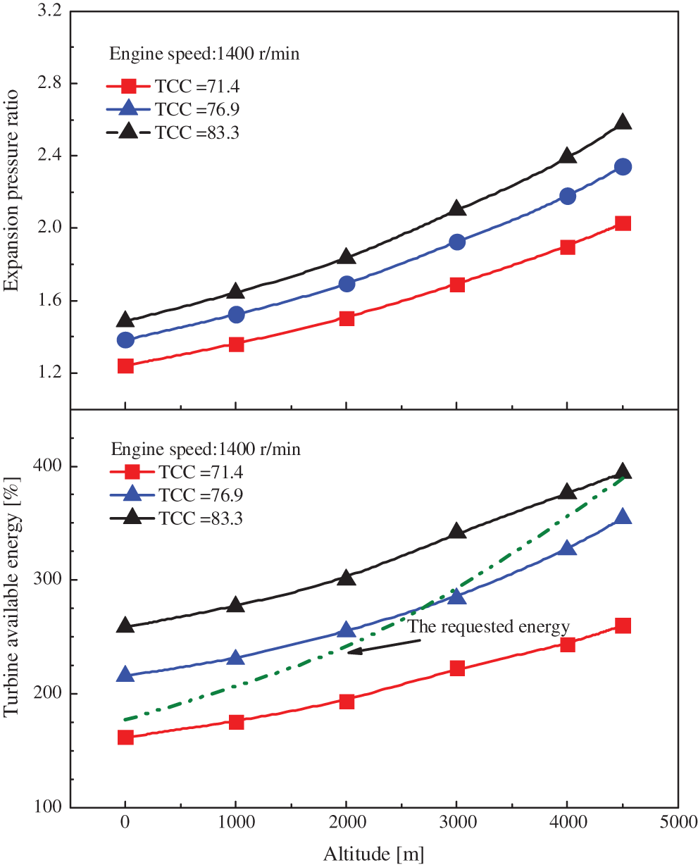
Figure 7: The effects of TCC on the expansion ratio and the turbocharger energy at different altitudes
Fig. 8 shows the TCC ratio (the ratio of the required TCC to the designed TCC) vs. the altitude for different overall efficiencies. As the overall efficiency changes from 0.42 to 0.54, the TCC ratio jumps from 0.68 to 1.88 in the altitude range of 0 to 4500 m. To maintain a constant boost pressure at different altitudes, the TCC should be reduced when the overall efficiency increases. For a specific overall efficiency, considering the exhaust energy of the boost pressure recovery, the required TCC needs to be increased with the altitudes.

Figure 8: TCC ratio vs. altitude for different overall efficiencies
For a fixed turbocharge system, the TCC cannot be changed as the altitudes. In this case, the boost pressure is difficult to be recovered unless the overall efficiency is decreased. Therefore, a better way to boost pressure recovery is to design a turbine system that can adjust TCC within wide ranges and maintain the overall efficiency a constant under variables altitudes.
3.3 Maximum Operation Altitude vs. Turbine Power Capability
The maximum operating altitude is determined by the turbocharger energy and the acceptable excess air ratio. The turbocharger energy is determined by TCC, which reflects the adaptability of turbocharge. The excess air ratio represents the adaptability of combustion. Fig. 9 shows the maximum operating altitude vs. the acceptable excess air ratio under the different TCCs. It is clear that the maximum operating altitude shows an upward trend with the increase of TCC and the decrease of the excess air ratio. The decrease of TCC by about 12% will increase the intake air pressure, which can compensate the pressure decrease due to the altitude increase by 1000 m. If the acceptable excess air ratio can be decreased by 0.1 through the combustion optimization, the operating altitude is also able to increase by approximately 1000 m. However, this is usually difficult to be achieved.
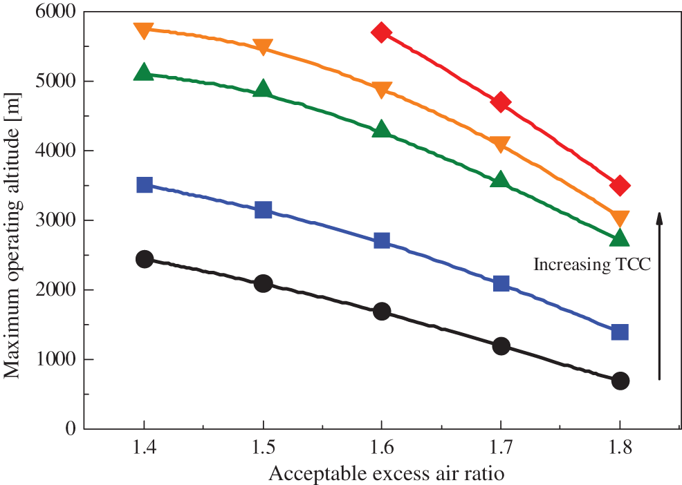
Figure 9: The maximum operating altitude vs. the acceptable excess air ratio under the different TCCs
In this subsection, the effects of the turbine’s power capability on the boost pressure recovery at different altitudes are analyzed. Fig. 10 shows the boost pressure vs. engine speeds and altitudes under large and small TCCs. As illustrated in the figure, when the engine speed exceeds 1600 r/min, the boost pressure can be maintained at the pressure corresponding to the sea level due to sufficient turbocharger energy. However, differences can be observed at low engine speeds and high altitudes. When the TCC is small, the boost pressure decreases rapidly as altitude increases at low speeds, because a small TCC cannot provide sufficient exhaust energy to achieve boost pressure recovery. At 1400 r/min, the boost pressure drops from 200 to 147.6 kPa (by about 26%) as the altitude increases from 0 to 3000 m. In contrast, when the TCC is large, the boost pressure can be effectively recovered even though at low speeds and high altitudes. At 1300 r/min, the boost pressure drops from 183.5 to 178 kPa (by around 3%) when the altitude increases from 0 m to 3000 m. As the speed increases to 1400 r/min, the boost pressure is fully recovered to the level at 0 m altitude due to the high exhaust energy.
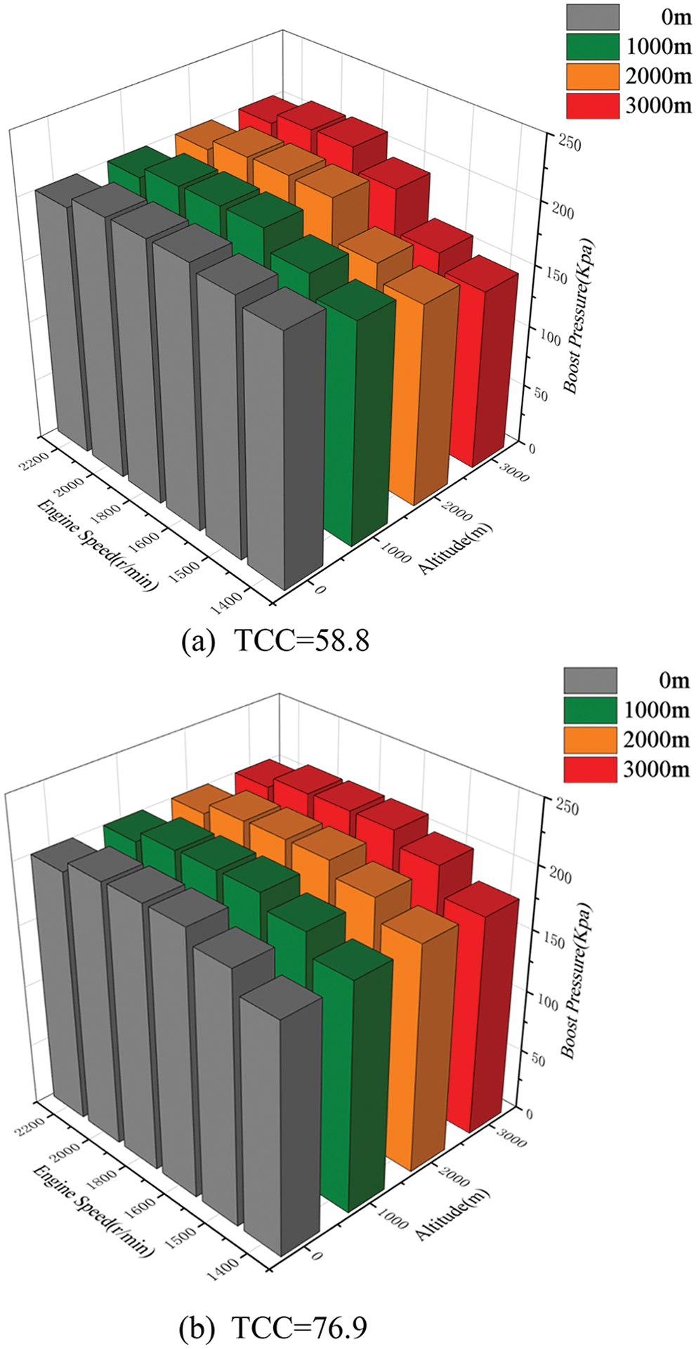
Figure 10: Boost pressure vs. engine speeds and altitudes under different TCCs
The effects of TCC on engine power at different altitudes are analyzed. Fig. 11 shows the rates of torque recovery vs. the altitudes under different TCCs.
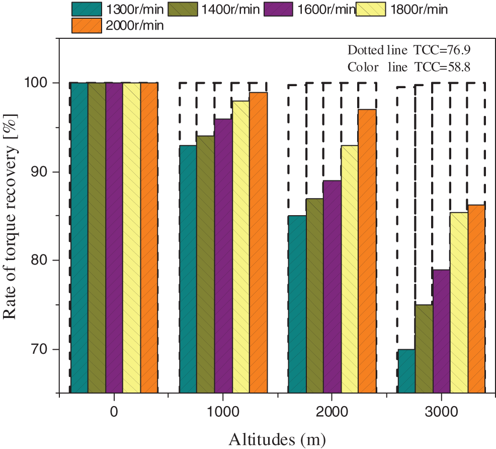
Figure 11: Rates of torque recovery vs. altitudes under different TCCs
As illustrated in the figure, when the TCC is small, the recovery of output torque decreases with the increase of the altitude, and the maximum loss of output torque occurs at low engine speeds. If the altitude is less than 2000 m, the torque recovery can exceed 85%. As the altitude increases to 3000 m, the torque loss reaches about 25% under the rated speed condition. This is due to the facts that the turbocharger energy is reduced and the boost pressure drops greater at lower engine speeds and higher altitudes. In contrast, when the TCC is large, the output torque recovery is increased with almost no loss, because a large TCC will lead to a rapid increase of turbocharger energy. The maximum gap between the target torque and the actual torque is smaller than 0.5%, which is acceptable in engineering applications. Therefore, a large TCC is more suitable at high altitudes, as it can provide sufficient turbocharger energy for engine torque recovery.
TCC is an effective parameter for controlling the turbocharger energy and the boost pressure, which can be applied to achieve engine power recovery over a wide range of altitudes. A small TCC is suitable for low altitudes to avoid overcharging, while a large TCC is preferred at high altitudes to provide sufficient boost pressure.
The value of TCC is adjusted by the wastegate of turbocharging system. Fig. 12 shows the TCC vs. engine speeds under different altitudes, in which the limits of the in-cylinder pressure, the turbocharger speed and the exhaust temperature are 180 bar, 180000 r/min and 750°C, respectively. As illustrated in the figure, when the altitude decreases, the wastegate gradually opens and the value of TCC decreases. The minimum TCC occurs under the rated speed condition of the sea level (the altitude is 0 m).
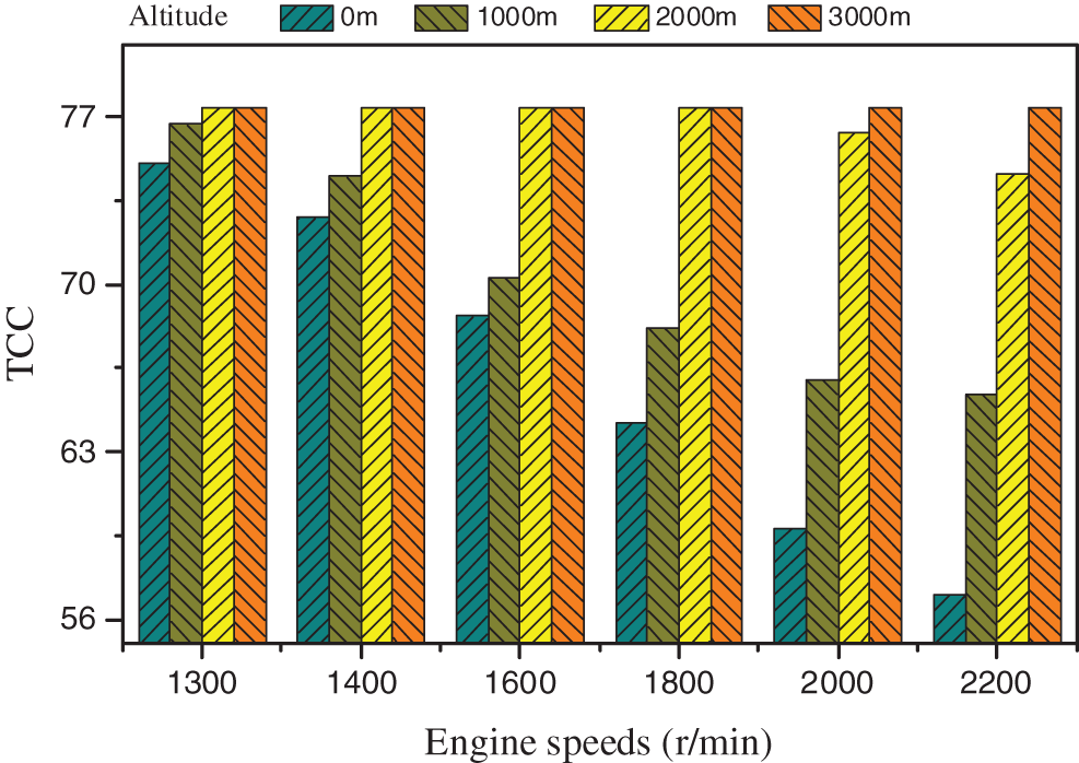
Figure 12: TCC of turbocharging system vs. engine speeds under different altitudes
4.3 Control Strategy of Turbocharging System
The influences of TCC on the performances of turbocharger and diesel engine have been discussed in above sections. The turbocharger energy can be adjusted by changing the value of TCC, as a result, the power recovery of diesel engine can be achieved under variable altitudes, as Fig. 13 shows schematic diagram of the control model for turbocharging system. In this model, the ideal target boost pressure is determined by the engine operating condition. A feedback regulation strategy is designed to control the TCC more accurately. An Anti-windup treatment is added to avoid extreme valve opening.
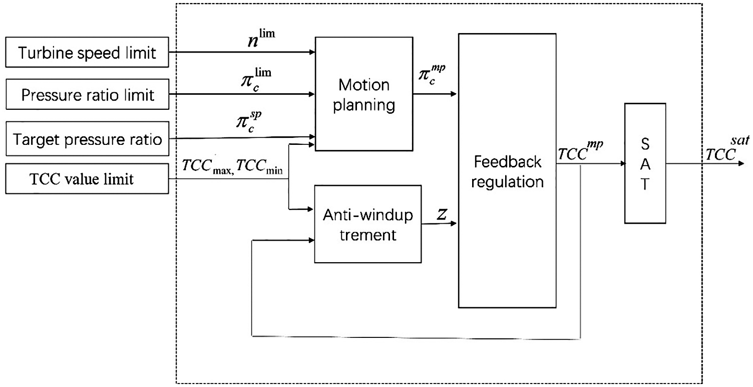
Figure 13: Schematic diagram of the control model for turbocharging system
Fig. 14 shows the control results under different altitudes. It is clear that the TCC value generally shows an upward trend with the increase of the altitude. As the altitude increases from 0 to 4500 m, the fluctuation range of the intake pressure is always less than 14.5 kPa. This suggests that the proposed control model can achieve a better recovery of boost pressure at different altitudes.
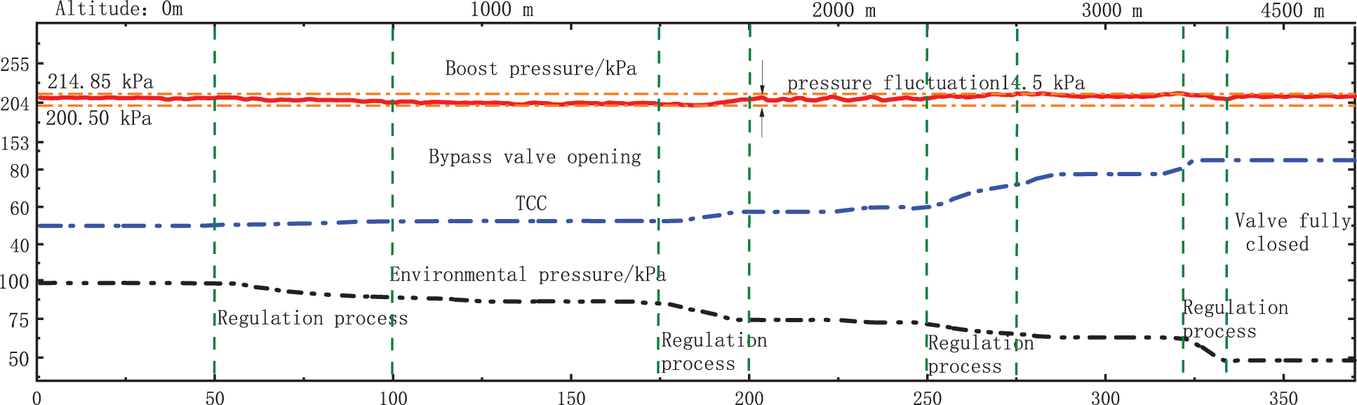
Figure 14: Control results under different altitudes
The effects of the power capability of turbines on turbocharger energy and diesel engine power at different altitudes are investigated. The numerical simulation method, which is validated by the experiment, is utilized to estimate the turbine performances for the simulation cases with variable TCC. The following conclusions are drawn:
1)The turbocharger energy is closely related to the TCC. When the TCC increases, the turbine inlet pressure will rise rapidly, which improves the turbocharger energy. As the altitude rises, the TCC needs to be increased to achieve high energy and boost recovery.
2)The engine torque is also correlated to the TCC at different altitudes. As the altitude rises, the compression ratio is demanded to increase to maintain the boost pressure. At high altitudes, a small TCC will decrease the engine torque due to the reduced boost pressure, especially at lower speeds of engine. A large TCC can maintain the boost pressure and torque of the engine at different altitudes due to the adequate energy provided by the turbine.
3)To make the performance of diesel engine recover as much as possible, the designed TCC should be large. Therefore, the engine power, which shows good recovery performance at the highest altitude, and can be switched to a smaller value at lower altitudes. Specifically, when the altitude changes from 0 to 3000 m, the TCC should be increased from 58.8 to 76.9 (improved by 30%).
4)The TCC is used as the energy regulation measurement to realize the effective recovery of boost pressure under variable altitudes. The fluctuation range of boost pressure is within 14.5 kPa for diesel engines when the altitude ranges from 0 to 4500 m.
5)The TCC control is an effective method to improve the high-altitude adaptability of the turbocharging system. The future studies will be focused on the methods to achieve a wider range of the TCC, and to control the TCC more accurately at different altitudes. These will improve the engine power, the fuel efficiency and the quality of emissions.
Funding Statement: This study is funded by the National Natural Science Foundation of China [Grant Nos. 51576129 and 12102298], the China Postdoctoral Science Foundation [Grant No. 2021M702443], and the State Key Laboratory of Engines (Tianjin University) [Grant No. K2022-09].
Conflicts of Interest: The authors declare that they have no conflicts of interest to report regarding the present study.
References
1. Liu, S., Leng, L., Zhou, W., Shi, L. (2021). Optimizing the exhaust system of marine diesel engines to improve low-speed performances and cylinder working conditions. Fluid Dynamics & Materials Processing, 17(4), 683–695. DOI 10.32604/fdmp.2021.013575. [Google Scholar] [CrossRef]
2. Sun, K., Li, D., Liu, H., Bai, S. (2020). Influence of diesel engine intake throttle and late post injection process on the rise of temperature in the diesel oxidation catalyst. Fluid Dynamics & Materials Processing, 16(3), 573–584. DOI 10.32604/fdmp.2020.09591. [Google Scholar] [CrossRef]
3. Zhu, J., Wang, X., Wang, H., Zhong, L., Li, Z. et al. (2022). Experimental analysis of the influence of exhaust thermal management on engine NOx emission. Fluid Dynamics & Materials Processing, 18(3), 701–711. [Google Scholar]
4. Zhang, Z., Liu, R., Zhou, G., Yang, C., Dong, S. et al. (2020). Influence of varying altitudes on matching characteristics of the Twin-VGT system with a diesel engine and performance based on analysis of available exhaust energy. Proceedings of the Institution of Mechanical Engineers, Part D: Journal of Automobile Engineering, 234(7), 1972–1985. [Google Scholar]
5. Jorge, M., Luis, R., Francisco, M., Daysi, B., Iván, Z. (2020). Effects of altitude in the performance of a spark ignition internal combustion engine. Materials Today: Proceedings, 49(1), 72–78. [Google Scholar]
6. Xu, Z., Ji, F., Ding, S., Zhao, Y., Zhang, X. et al. (2020). High-altitude performance and improvement methods of poppet valves 2-stroke aircraft diesel engine. Applied Energy, 276(1), 115471. DOI 10.1016/j.apenergy.2020.115471. [Google Scholar] [CrossRef]
7. Dennis, J. (1971). Turbocharged diesel engine performance at altitude. SAE Transactions, 2670–2689. [Google Scholar]
8. Ángel, R., Reyes, G., Octavio, A. (2016). Performance, combustion timing and emissions from a light duty vehicle at different altitudes fueled with animal fat biodiesel, GTL and diesel fuels. Applied Energy, 182(4), 507–517. DOI 10.1016/j.apenergy.2016.08.159. [Google Scholar] [CrossRef]
9. Zhu, Z., Zhang, F., Li, C., Wu, T., Han, K. et al. (2015). Genetic algorithm optimization applied to the fuel supply parameters of diesel engines working at plateau. Applied Energy, 157(3), 789–797. DOI 10.1016/j.apenergy.2015.03.126. [Google Scholar] [CrossRef]
10. Human, D., Ullman, T., Baines, T. (1990). Simulation of high altitude effects on heavy-duty diesel emissions. SAE Transactions, 1791–1800. DOI 10.4271/900883. [Google Scholar] [CrossRef]
11. Chaffin, C., Ullman, T. (1994). Effects of increased altitude on heavy-duty diesel engine emissions. SAE Technical Paper, 940669. [Google Scholar]
12. Zhang, H., Shi, L., Deng, K., Liu, S., Yang, Z. (2020). Experiment investigation on the performance and regulation rule of two-stage turbocharged diesel engine for various altitudes operation. Energy, 192(6), 116653. DOI 10.1016/j.energy.2019.116653. [Google Scholar] [CrossRef]
13. Zhang, H., Tang, X., Mu, L., Shi, L., Deng, K. (2021). Theoretical and experimental investigation of the pressure ratio distribution and the regulation strategy of a two-stage turbocharging system for various altitudes operation. Journal of Mechanical Science and Technology, 35(3), 1251–1265. DOI 10.1007/s12206-020-1231-z. [Google Scholar] [CrossRef]
14. Wang, X., Ge, Y., Yu, L., Feng, X. (2013). Effects of altitude on the thermal efficiency of a heavy-duty diesel engine. Energy, 59, 543–548. DOI 10.1016/j.energy.2013.06.050. [Google Scholar] [CrossRef]
15. Zhang, H., Shi, L., Deng, K., Liu, S., Yang, Z. (2020). Experiment investigation on the performance and regulation rule of two-stage turbocharged diesel engine for various altitudes operation. Energy, 192(6), 116653. DOI 10.1016/j.energy.2019.116653. [Google Scholar] [CrossRef]
16. Yang, M., Gu, Y., Deng, K., Yang, Z., Liu, S. (2018). Influence of altitude on two-stage turbocharging system in a heavy-duty diesel engine based on analysis of available flow energy. Applied Thermal Engineering, 129(3), 12–21. DOI 10.1016/j.applthermaleng.2017.09.138. [Google Scholar] [CrossRef]
17. Soares, S., Sodre, R. (2002). Effects of atmospheric temperature and pressure on the performance of a vehicle. Proceedings of the Institution of Mechanical Engineers, Part D: Journal of Automobile Engineering, 216(6), 473–477. DOI 10.1243/09544070260137499. [Google Scholar] [CrossRef]
18. Szedlmayer, M., Kweon, C. (2016). Effect of altitude conditions on combustion and performance of a multi-cylinder turbocharged direct-injection diesel engine. SAE Technical Paper, 2016-01-0742. [Google Scholar]
19. Galindo, J., Serrano, R., Climent, H., Varnier, O. (2010). Impact of two-stage turbocharging architectures on pumping losses of automotive engines based on an analytical model. Energy Convers Manage, 51(10), 1958–1969. [Google Scholar]
20. Mansouri, H., Ommi, F. (2019). Performance prediction of aircraft gasoline turbocharged engine at high-altitudes. Applied Thermal Engineering, 156, 587–596. DOI 10.1016/j.applthermaleng.2019.04.116. [Google Scholar] [CrossRef]
21. Zhang, H., Zhuge, W., Zhang, Y. (2008). Study of the control strategy of the plateau self-adapted boosting system for diesel engine. SAE Papers, 2008-01-1636. [Google Scholar]
22. Liu, X., Wei, M., Ma, C. (2010). Simulation on one-stage and two-stage turbocharged diesel engines at different altitudes. Transactions of Chinese Society for Internal Combustion Engines, 28(5), 447–452. [Google Scholar]
23. Shi, X., Li, W. (2011). Simulation on plateau performance of diesel engine matched with two-stage sequential boosting system. Acta Armamentarii, 32(4), 397–401. [Google Scholar]
24. Katrašnik, T., Trenc, F. (2012). Innovative approach to air management strategy for turbocharged diesel aircraft engines. Proceedings of the Institution of Mechanical Engineers, Part G: Journal of Aerospace Engineering, 226(8), 966–979. DOI 10.1177/0954410011416750. [Google Scholar] [CrossRef]
25. Liu, R., Yang, C., Zhang, Z., Jiao, Y., Zhou, G. (2019). Experimental study on thermal balance of regulated two-stage turbocharged diesel engine at variable altitudes. Journal of Thermal Science, 28(4), 682–694. DOI 10.1007/s11630-019-1151-3. [Google Scholar] [CrossRef]
26. Wang, X., Ge, Y., Yu, L., Feng, X. (2013). Effects of altitude on the thermal efficiency of a heavy-duty diesel engine. Energy, 59, 543–548. DOI 10.1016/j.energy.2013.06.050. [Google Scholar] [CrossRef]
27. Liu, R. (2013). Research on plateau environmental adaptability of diesel engines, pp. 99–110. Beijing, China: Beijing Institute of Technology Press. [Google Scholar]
28. Liu, R., Zhou, G., Dong, S. (2011). Experimental study on performance of turbocharged diesel engine at high altitude. International Conference on Electric Information and Control Engineering, pp. 4188–4190. IEEE. [Google Scholar]
29. Ghazikhani, M., Davarpanah, M., MousaviShaegh, S. (2008). An experimental study on the effects of different opening ranges of waste-gate on the exhaust soot emission of a turbo-charged DI diesel engine. Energy Conversion and Management, 49(10), 2563–2569. DOI 10.1016/j.enconman.2008.05.012. [Google Scholar] [CrossRef]
30. Li, H., Zhang, G., Zhang, H., Shi, L., Yang, M. et al. (2016). Equivalent matching model of a regulated two-stage turbocharging system for the plateau adaptability. Proceedings of the Institution of Mechanical Engineers, Part D: Journal of Automobile Engineering, 230(12), 1654–1669. DOI 10.1177/0954407015619070. [Google Scholar] [CrossRef]
31. Yang, M., Gu, Y., Deng, K., Yang, Z., Zhang, Y. (2018). Analysis on altitude adaptability of turbocharging systems for a heavy-duty diesel engine. Applied Thermal Engineering, 128(10), 1196–1207. DOI 10.1016/j.applthermaleng.2017.09.065. [Google Scholar] [CrossRef]
32. Watson, N., Janota, S. (1982). Turbocharging the internal combustion engine, pp. 327–375. London: McMillan Publishers, Ltd. [Google Scholar]
33. Payri, F., Benajes, J., Jullien, J. (1991). Non-steady flow behavior of supercharger turbine. Proceedings of the Third EAEC International Conference, pp. 347–351. Strasbourg, Springer. [Google Scholar]
34. Payri, F., Benajes, J., Reyes, M. (1996). Modelling of supercharger turbines in internal-combustion engines. International Journal of Mechanical Sciences, 38(8–9), 853–869. DOI 10.1016/0020-7403(95)00105-0. [Google Scholar] [CrossRef]
Cite This Article
 Copyright © 2023 The Author(s). Published by Tech Science Press.
This work is licensed under a Creative Commons Attribution 4.0 International License , which permits unrestricted use, distribution, and reproduction in any medium, provided the original work is properly cited.
 Downloads
 Citation Tools