
 Submit a Paper
 Propose a Special lssue
 Open Access
ARTICLE

Investigation of the Effects of a Large Percentage of Dried Sludge on the Operation of a Coal-Fired Boiler
1 Hangzhou E-Energy Technology Co., Ltd., Hangzhou, 310014, China
2 North China Electric Power University, Baoding, 071003, China
* Corresponding Author: Xuemin Ye. Email:
Fluid Dynamics & Materials Processing 2023, 19(4), 1027-1041. https://doi.org/10.32604/fdmp.2022.022303
Received 03 March 2022; Accepted 30 May 2022; Issue published 02 November 2022
 View Full Text
 Download PDF
Abstract
A 600 MW coal-fired boiler with a four-corner tangential combustion mode is considered here to study the combustion features and pollutant emissions at different loads for large-percentages of blending dried sludges. The influence of the over-fired air (OFA) coefficient is examined and the impact of the blending ratio on the boiler operation is explored. The results show that for low blending ratios, a slight increase in the blending ratio can improve the combustion of bituminite, whereas a further increase leads to the deterioration of the combustion of blended fuels and thus reduces the boiler efficiency. Enhancing the supporting capability of the secondary air effectively reduces the slagging degree in the bottom ash hopper and improves the burnout rate of coals. For a large-percentage blending case at full load, it is found that the OFA coefficient must be reduced appropriately, otherwise, a secondary high-temperature combustion zone can be generated in the vicinity of the furnace arches, causing high temperature slagging and superheater tube bursting. Considering the influences of combustion and pollutant emissions, the recommended OFA coefficient is 0.2. Blending dried sludge under low loads increases the flue gas temperature at the furnace exit. While reducing the flue gas temperature in the main combustion region, which is beneficial to the safe operation of the denitrification system. Increasing the blending ratio and reducing load lead to an increase in NOx concentration at the furnace exit Sludges with low nitrogen content are suggested for the practical operation of boilers.Graphic Abstract
Keywords
Coal-fired power generation mixed with biomass is one of the most important directions to travel in should the target of low-carbon emissions be realized. Recently, a transformation of coal-biomass co-combustion in coal-fired boilers has been implemented in many power generation units. Sludges, as one of the reuse fuels, have the characteristics of high moisture, high volatile content, low fixed carbon, and low calorific value. Published studies have shown that the direct combustion of sludges requires additional fuels, e.g., coal, leading to an expensive operating cost [1]. Therefore, sludges are conventionally dried and co-fired with coals. Blending dried sludges in coal-fired boilers can not only realize the resource utilization of sludges, but can also reduce the cost of environmental protection as well.
Dioxins are a class of refractory carcinogens with thermal stability, which are decomposed and destroyed at a temperature over 850°C. The furnace temperature of pulverized coal boilers is approximately 1200°C, and the residence time of more than 2 s meets the requirements for the decomposition and destruction of dioxins. Dioxin production cannot be inhibited in circulating fluidized bed boilers (CFBBs) due to the low temperature inside furnaces of 800°C–850°C. Additionally, the high ash content of sludges causes possible wearing of heating surfaces in boilers. Generally, the wearing of heating surfaces in CFBBs is more severe than in pulverized coal boilers, resulting in higher maintenance costs. Hence, the coal-sludge co-combustion in pulverized coal boilers is a viable path to address the generation of dioxins and make full use of the thermal energy of sludges.
Many experimental studies were conducted on the combustion characteristics of sludges. Vesilind et al. [2] found that the combustion residue of sludges did not have any calorific value when the temperature exceeds 400°C using the thermogravimetric analysis. Ogada et al. [3] showed that both the volatile matter volatilization and water evaporation proceed simultaneously, and the combustion efficiency was mainly dependent on volatile matter. Tang et al. [4] investigated the combustion features at different heating rates and blending ratios of sludges and found that the weight loss rate of sludges is negatively correlated with the heating rate. Folgueras et al. [5] examined the pyrolysis and combustion properties of the mixture of sludge and bituminite during the heating and combustion at 25°C–800°C and found no interaction between the components of the two fuels throughout the heating and combustion process.
Other reports mainly focused on the effect of the moisture content and blending ratio of sludges on boiler operation [6–9], in which the blending percentage was small and did not exceed 10%. And the optimization of sludge co-combustion in coal-fired boilers mainly was carried out with numerical simulation. The duo-mixture fraction/PDF model was used to simulate co-combustion features [10], in which sludges and pulverized coals were treated as two fuels. However, in this model, because the dry basis of fuels is regarded as the input condition, the effect of moisture changes in sludges on combustion processes cannot be accurately predicted. Hence, moisture must be involved when simulating the co-combustion of coal and sludge with high moisture content. For a 100 MW coal-fired boiler, Zhu et al. [11] examined the adaptability under different moisture contents and blending ratios when blending sewage sludges using the duo-mixture fraction/PDF model and the eddy-dissipation model (EDM). They found that the EDM model accurately simulates the impact of blending ratio and moisture content on the combustion and pollutant emission. By blending a sludge with a moisture content of 56% in a pulverized coal boiler, Zhang et al. [12] found a slight impact on the combustion when the blending percentage is less than 20%. Additionally, several reports [13,14] documented the influence of blending different sorts of wet sludges, secondary air distribution modes, blending ratios, and excess air coefficients and pollutant emissions in pulverized coal boilers.
The aforementioned studies have mainly focused on the influence of high-moisture sludges on combustion in pulverized coal boilers, but the blending ratio is generally low. Additionally, an increase in the calorific value after sludges dry proves that it is feasible to raise the blending ratio at full load, thereby further promoting the resource utilization degree of sludges. Moreover, since the frequency and degree of deep peak-load regulation in coal-fired units are raised, the feasibility and blending ratio under low loads needs to be studied. Therefore, in this study, for a 600 MW coal-fired boiler, the EDM model is employed to simulate the combustion and pollutant emission for large blending ratios of dried sludges under full load and the impact of the OFA coefficient under large blending ratios is investigated to provide a viable scheme for coal-fired boilers with large blending ratios of dried sludges.
A 600 MW coal-fired boiler with a corner tangential firing is selected, characterized by a П-type steam drum, single furnace, single reheating, and natural circulation, as shown in Fig. 1. The furnace height, width, and depth are 62.7, 19.5 and 17.4 m, respectively. The milling system is equipped with six medium-speed and direct-fired pulverizers, of which five are operating and one is on standby. In this simulation, six burners are in operation for the blending ratio of 40% under full load, and the uppermost mill is halted under off-design loads. As the load decreases, pulverizers are stopped from the top layer to the bottom layer according to the fuel demand. The combustion system is arranged in a four-corner tangential combustion mode, and the main combustion zone is equipped with six layers of primary air, indicating with A–F from the bottom to the top. Four primary air nozzles in the same layer are supplied with the air and coal by one pulverizer. The burners in layer A adopt plasma burners, burners in other layers utilize bias bluff body burners, in which the adjacent burners generate two opposite coal concentration directions, forming three groups of node function zones, AB, CD, and EF. The angles between the axis of the burner and the front and rear walls are 40° and 47°, respectively. Each burner is configured with the secondary air nozzles above and below the burner, and the two-layer secondary air nozzles (named AA, AB, BC, CD, DE, EF, FF, OFA) are arranged at the upper side of the uppermost burner. Seven-layer separated combustion air nozzles (SOFA1-SOFA7) are configured in the burnout zone above the main combustion zone.
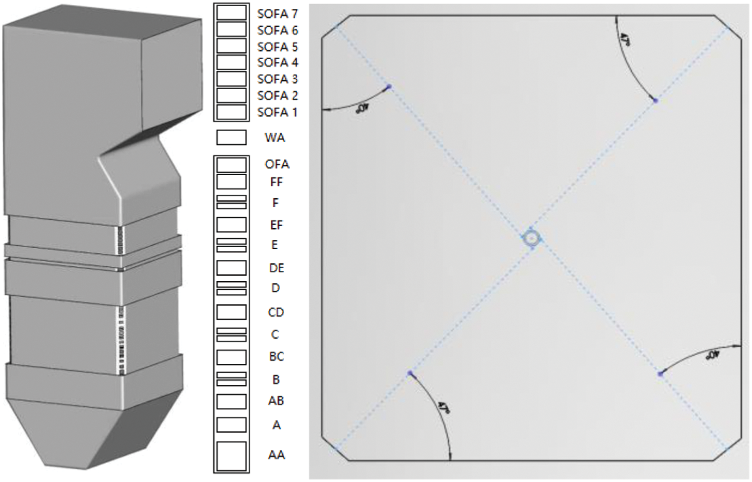
Figure 1: Diagram of boiler and cross-sectional view of the furnace
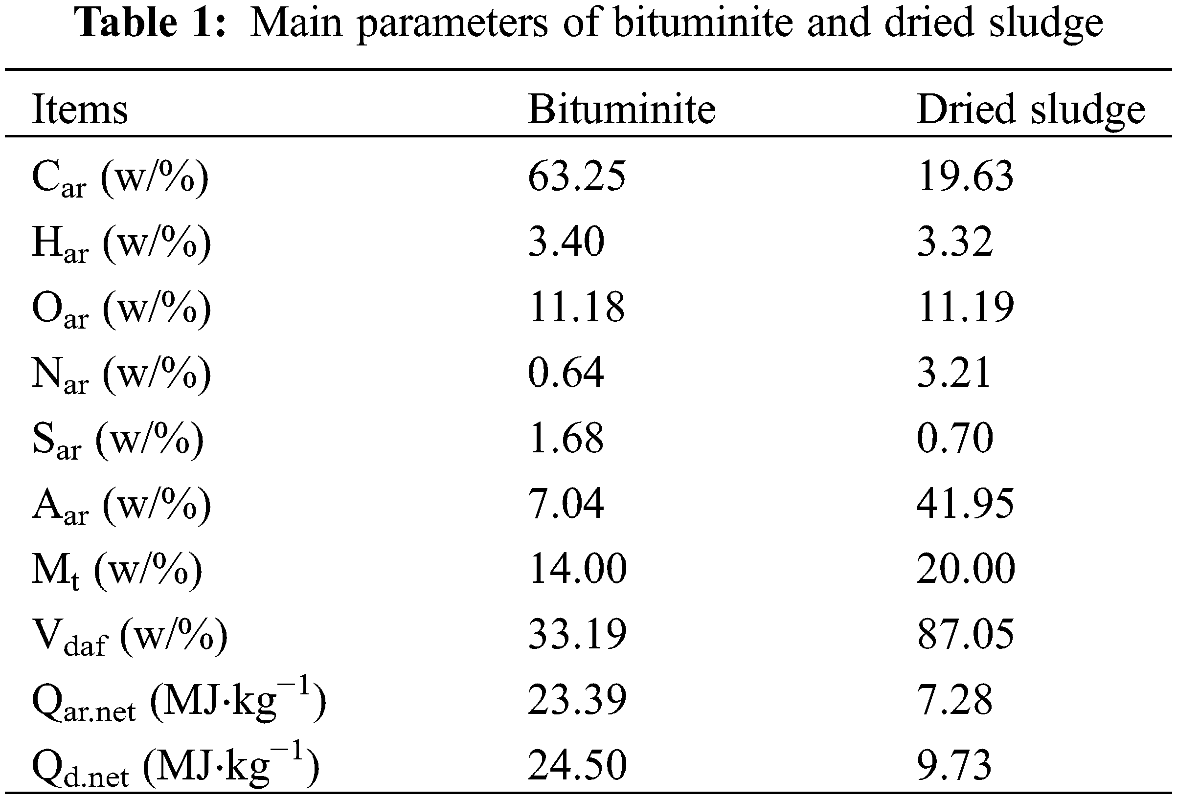
The designed coal of Shenhua, bituminite and sludge with 20% moisture content after drying is selected for the present study. Table 1 lists the ultimate and proximate analysis of the bituminite and dried sludge. It is found that the fixed carbon content and calorific value of dried sludge are far less than bituminite, and the ash content is very high. It is believed that increasing the blending ratio of the sludge inevitably leads to a significant impact on the combustion properties in the furnace.
2.2 Numerical Method and Boundary Conditions
The furnace model consists of five regions: the cold ash hopper zone, the main combustion zone, the reduction zone, the burnout zone, and the upper zone of the furnace outlet. ICEM-CFD software is used to create structured meshes, and the interface is employed for data exchange. To avoid false diffusion, the direction of mesh lines is consistent with the direction of the nozzle axis in the main combustion zone and the burnout zone. And to improve the simulation accuracy, the mesh in the burner region is intensified, as shown in Fig. 2.
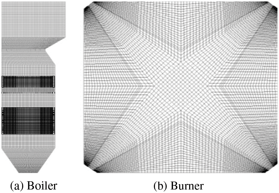
Figure 2: Mesh of boiler and burner
Fluent 17.0 is applied to solve the steady 3D continuity and Reynolds averaged Navier-Stokes (RANS) equations. The coal combustion process includes pyrolysis, volatile combustion, char combustion, and inert heating. For simulating coal-sludge co-combustion, the following models are employed: the standard k-ε turbulence model for the gas-phase turbulence model [15], the kinetics/diffusion-limited combustion model for char combustion, the P-1 radiation model for radiation heat transfer which can obtain accurate results with a less computation time [11], the discrete random walk model for the turbulent motion of pulverized coal and sludge particles [13], the two competing rates model for the volatile pyrolysis simulation [14], the eddy-dissipation model for the species transport and gas-phase combustion, and a two-step reaction model for the volatilization release [16], in which CO is first generated then CO2 is formed, and it is suitable for the simulation of low oxygen combustion with pollutant NOx generation and reduction processes.
The post-processing method is used to obtain the NOx distribution. Among the three types of NOx generated during combustion, the prompt NOx is not considered due to a negligible proportion. The De-Soete mechanism for the thermal NOx generation and the Zeldovich mechanism [17] for fuel NOx are employed for this simulation.
Based on the assumption of a quasi-steady process, a steady-state solver is applied for the present simulation. The pressure terms are addressed with the standard discretization, and other terms are addressed with the second-order discretization. The SIMPLE algorithm is employed to address the pressure-velocity coupling [18]. The inlet boundary is the velocity inlet for each inlet, and the outlet boundary is the pressure-outlet with a pressure of –80 Pa. No-slip boundary condition is utilized for all walls. The temperature in water-cooled walls is set to 800 K. The heat transfer mode in the furnace is heat radiation. The complex temperature distribution at the water-cooled walls needs to be simplified when simulating the combustion in a furnace. It is found that the wall temperature of 800 K is used for the 600 MW boiler, and that the flue gas temperature at the furnace outlet is well consistent with the actual value. The particle size of coal and sludge adopts the Rosin-Rammler diameter distribution [14], that is, the minimum and maximum sizes are 5 and 250 μm, respectively, and the average size is 60 μm. It has been verified that the Rosin-Rammler diameter distribution is in accord with the actual distribution.
The governing equations, including the steady 3D continuity, RANS equations, standard k-ε turbulence model, and energy equation, are formulated as follows:
where
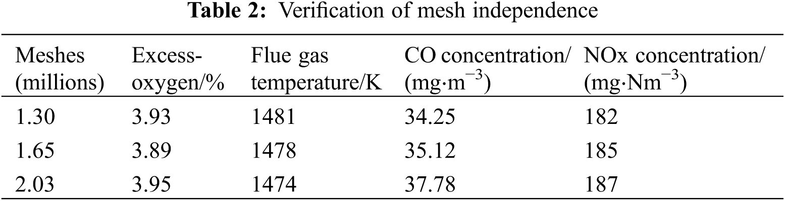
In this simulation, the grid is composed of multiple structured grids, and the grid quality is above 0.6. To verify the grid independence, three groups of mesh are selected for the modeling under full load, as shown in Table 2. By comparing the average flue gas temperature and the component concentration at the furnace outlet and considering the computation time, a mesh number of 1.65 million is employed in the following.
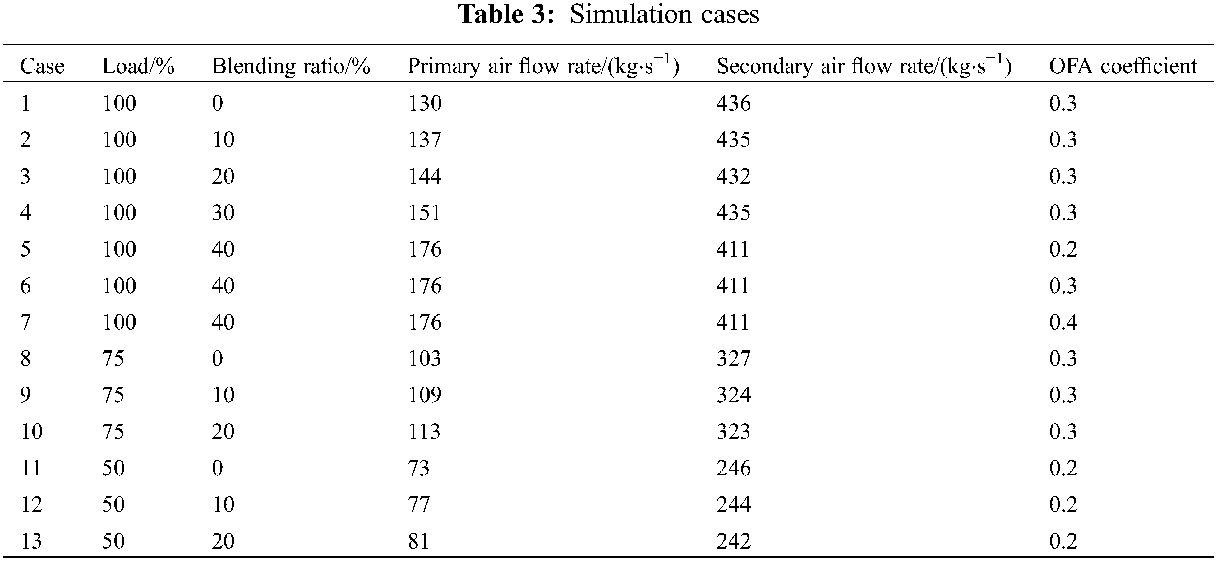
The fuel mass is calculated with the low heating value for all cases, and the same blending ratio is applied to all burners in each layer. The blending ratio of dried sludge has an essential impact on the operation of coal-fired boilers. Hence, the selected range of blending ratios should ensure stable combustion and safe operation and meet environmental protection requirements. Hence in practical applications, the maximum blending ratio is roughly 40% at full load. The specific parameters of various simulated cases are presented in Table 3. The excess air ratio under full load is 1.2. Seven cases are considered in this study: Case 1 is the reference case without sludge blending, and Cases 2–6 represent a blending ratio of 10%, 20%, 30%, and 40%. As increasing blending ratio leads to an increment of a load of a single pulverizer, except for the 40% blending ratio case where six pulverizers are put into operation in the layers of A–E, other cases employ five pulverizers in A–E layers. In addition, to examine the impact of the OFA coefficient on large blending ratios, three cases are further investigated, in which Cases 5–7 represent the OFA coefficient of 0.2, 0.3, and 0.4, respectively. Under variable loads, Cases 8–10 represent the operation conditions of a blending ratio of 0%–20% under 75% load, and Cases 11–13 represent a blending ratio of 0%–20% under 50% load. The operated burners at different loads are five-layer burners (Cases 1–3), four-layer burners (Cases 8–10), and three-layer burners (Cases 11–13), respectively. In this simulation, the NOx concentration is corrected to the concentration in the dry flue gas at 6% oxygen content under the standard condition.
3.1 Influence of Blending Ratio under Full Load
Fig. 3 shows the influence of the blending ratio on the temperature field in the furnace under a full load. With an increase in blending ratio, the average flue gas temperature at the cross-section of burners in each layer presents a downward variation. Taking the lowermost burner as an example (Fig. 3a), an annular high-temperature region is observed at the cross-section of burners, while the temperature at the center is low, indicating a reasonable pattern of the tangential combustion mode. With increasing blending ratio, the temperature at the burner cross-section decreases, and the high-temperature region gradually shrinks toward the burner nozzles, where the average flue gas temperature under a blending ratio of 40% (Case 6) is the lowest, and the high-temperature region is the smallest. This is because the calorific value of the dried sludge is much lower than the bituminite.
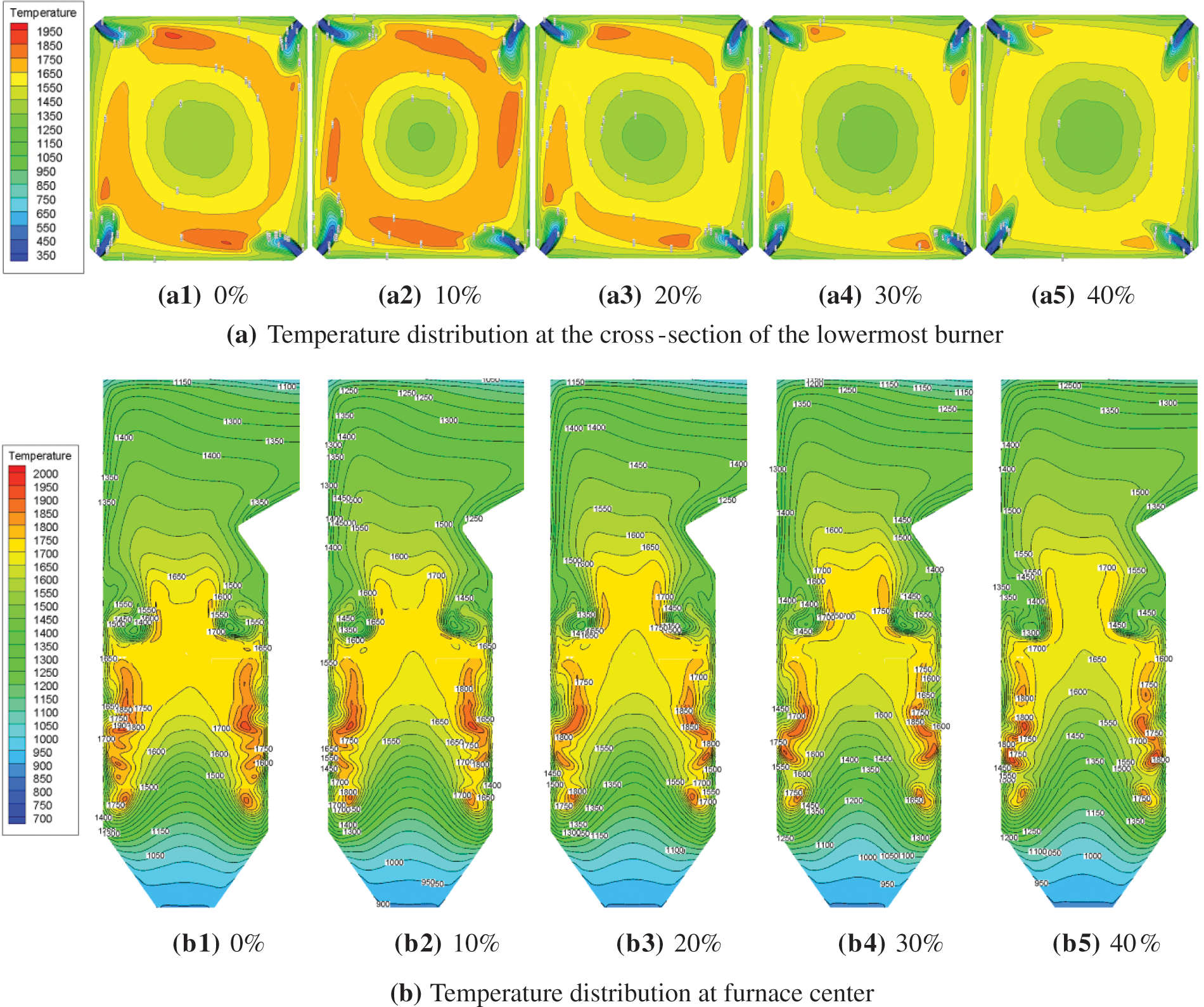
Figure 3: Effect of blending ratio of dried sludge on the furnace temperature field
As the blending ratio increases, the heating value of the blended fuel continues to decrease, and the combustion then tends to be worse. To ensure the stability of the boiler load, the net heating value of the fuel remains the same for each case, which requires the mass of the blended fuel to vary in the same way as the blending ratio. Hence the primary air rate increases and the degree of incomplete combustion is strengthened, resulting in a reduction in the average flue gas temperature. Additionally, with an increasing blending ratio, the contents of volatiles and moisture in the blended fuel also rise gradually, whereas the content of fixed carbon continues to decrease. The volatile content releases and burns out rapidly, becoming completely burned and used up in about 0.1 s at the position close to burners. It indicates that with an increase in blending ratio, the high-temperature region at the cross-section of burners gradually weakens and approaches burners.
Fig. 3b displays the temperature distribution at the cross-section of the furnace. With an increase in blending ratio, the overall average flue gas temperature decreases, the flame center gradually moves upwards, and the temperature above the burnout zone rises, which is the most apparent feature in Case 6. That is because increasing the blending ratio raises the quantity of fuel and primary air, resulting in the combustion being delayed. In addition, a large amount of air is required for the burnout zone, where CO and remaining char continue to burn, thereby raising the flue gas temperature above the furnace.
Figs. 4 and 5 depict the influence of the blending ratio on the distribution of average flue gas temperature and components along with the furnace height. As shown in Fig. 4, due to the alternate arrangement of primary air and secondary air in the main combustion zone, the mixing of the primary air and secondary air with the high-temperature flue gas causes the average temperature and components to fluctuate. Along with the furnace height, the average flue gas temperature at the cross-section of burners decreases gradually with the blending ratio. For a blending ratio of 10%, the variation in average flue gas temperature is consistent with that reported in the literature [15]. With an increase in the blending ratio, the maximum temperature difference between Case 1 and Case 6 above the main combustion zone reaches up to 115 K; the oxygen and CO concentrations rise. In addition, in the region above the E-layer burners, the average flue gas temperature in Cases 1–4 increases significantly, which is quite different from Case 6. The possible reason is that the primary air input in the F-layer of Case 6 reduces the flue gas temperature.
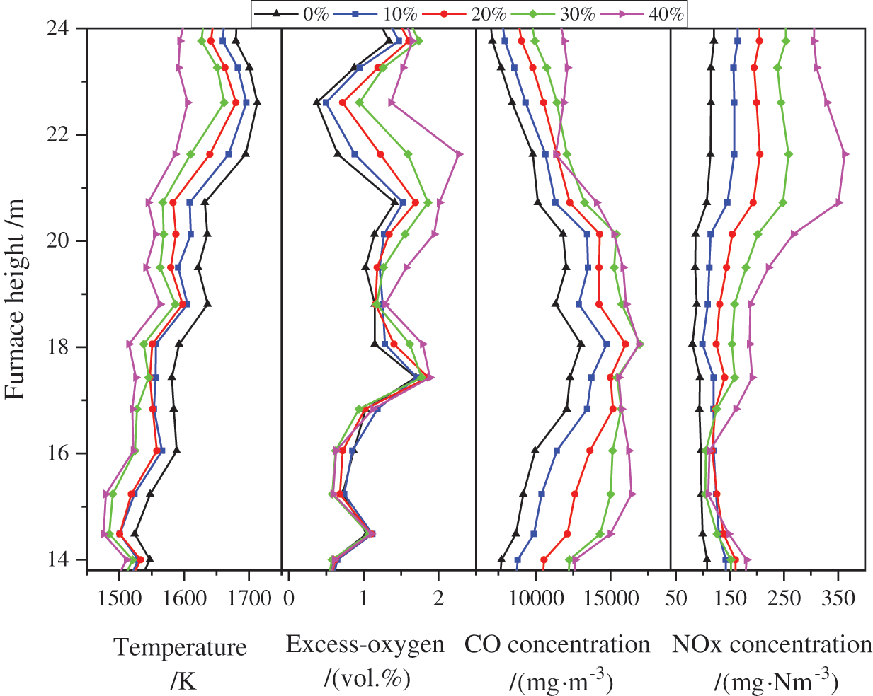
Figure 4: Effect of blending ratio on average flue gas temperature and components in the main combustion zone
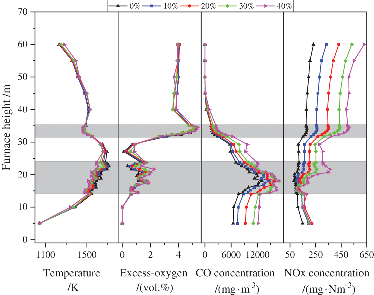
Figure 5: Effect of blending ratio on average flue gas temperature and components along with the furnace height
It is found from Fig. 5 that the average flue gas temperature for each case reaches a peak value in the reduction zone, then gradually decreases. In the region below the burnout zone, the average flue gas temperature drops with the blending ratio; but above the burnout zone, the flue gas temperature increases with the blending ratio. It is because with increasing the blending ratio, the degree of incomplete combustion in the combustion zone is aggravated while a large amount of air is added to the burnout zone. Hence CO and unburnt particles continue to burn and are oxidized, thereby changing the flue gas temperature distribution in the regions above the burnout zone. Moreover, with an increase in blending ratio, the flue gas temperature at the furnace outlet also increases gradually.
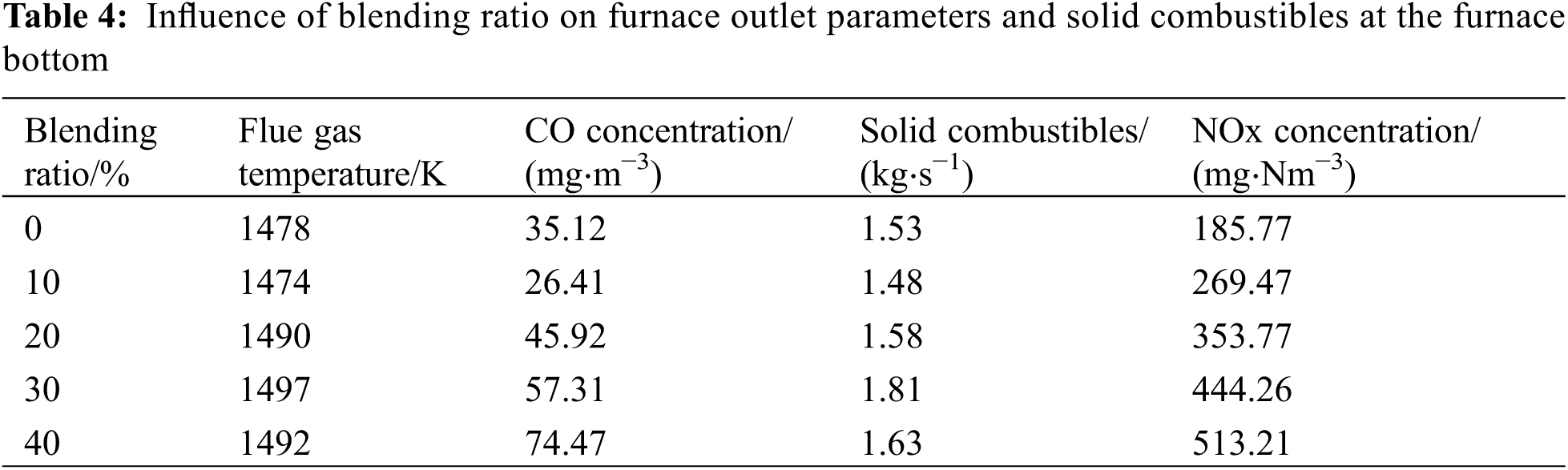
The influence of the blending ratio on the coal burnout rate is very complicated. Variations in CO concentration at the furnace outlet and the mass of solid combustibles at the furnace bottom could reflect the burnout rate of blended fuels. As shown in Table 4, the CO concentration in Case 2 decreases slightly compared with Case 1 due to a low blending ratio in Case 2, and it increases when raising the blending ratio. The variation in solid combustible mass in Case 2 is slightly different from Case 6, which is because the total amount of blended fuel increases with an increased blending ratio, and the uppermost burner is required to put into operation in Case 6. The supporting effect of the secondary air on the fuel is enhanced, resulting in a reduction of solid combustible mass falling into the ash hopper. Meanwhile, the flue gas temperature at the furnace outlet in Case 2 decreases compared with Case 1, indicating that the high volatile content of the dried sludge improves the combustion of bituminite to some degree and extent. When the blending ratio is further increased, the flue gas temperature at the furnace outlet gradually rises, indicating that the combustion of the blended fuel tends to be worse. The significantly increased fuel results in obviously delayed combustion and the upward movement of the flame center.
In addition, the NOx concentration at the furnace outlet increases obviously as the blending ratio increases. Along with the furnace height, with increasing blending ratio, the NOx concentration in the main combustion zone and above raises distinctly. Since the nitrogen content of the sludge is much higher than bituminite, increasing the blending ratio leads to a continuous increase in the nitrogen content in the blended fuel, especially for Case 6, the blending ratio is as high as 40%, and the amount of fuel NOx generation increases significantly.
When the maximum blending ratio is applied in practical operations, some necessary measures are required, including raising the capacity of milling systems and precipitators, and regulating the operating parameters and fiducial values of boiler systems to adapt to the new fuel characteristics.
3.2 Effect of OFA Coefficient at Full Load with the Large Blending Ratio
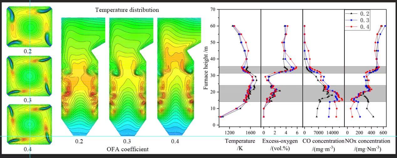
The above analysis verifies the possibility of a large blending ratio of dried sludge at full load. But, due to a significant increase in fuel quantity under the 40% blending ratio, the distributed airflow is quite different from other cases, so it is vital to investigate the influence of the OFA coefficient on furnace combustion. Fig. 6a illustrates that as the OFA coefficient increases, the flue gas temperature at the cross-section of burners decreases significantly, and a high-temperature region around burners is reduced. Fig. 7 shows that with increasing the OFA coefficient, the excess air coefficient in the main combustion zone drops, and the average flue gas temperature in the burnout zone and below decreases along with the furnace height. In contrast, the temperature field in the region above the burnout zone presents an opposite variation. The temperature distribution in the main combustion zone in Cases 6 and 7 is roughly the same, and the flue gas temperature reduces significantly compared with Case 5. In Case 7, there is a temperature peak near the furnace arch, indicating that the secondary high-temperature combustion zone is generated herein. The possible reason is that the degree of incomplete combustion in the main combustion zone is raised, then the fly ash contains a large amount of char, leading to the formation of enhanced secondary combustion above OFA nozzles. As shown in Fig. 6b, after increasing the OFA coefficient, the temperature above the furnace rises visibly, and the phenomenon of the delayed combustion and the rising flame center becomes increasingly remarkable. Hence a high OFA coefficient is likely to cause the slagging and tube bursting for secondary superheaters.
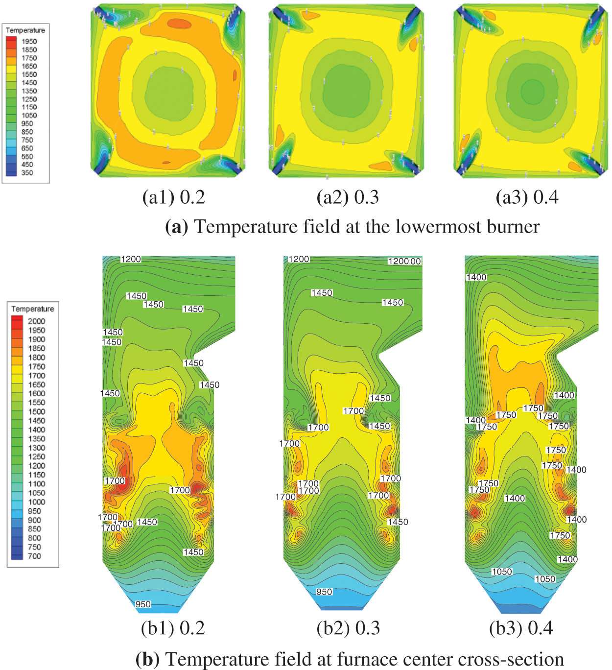
Figure 6: Effect of OFA on the temperature field
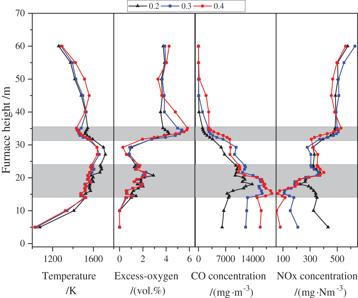
Figure 7: Effect of OFA on average flue gas temperature and flue gas components along with the furnace height
Table 5 presents the parameters at the furnace outlet and the mass of solid combustibles at the furnace bottom. With an increase in the OFA coefficient, both the mass of solid combustibles and the CO concentration show an upward variation, related to the delay of combustion and the rising movement of the flame center. The CO concentration in Case 7 is much higher than in the other two cases, while the NOx concentration presents a downward change with the OFA coefficient. The reason is that with increasing the OFA coefficient, the incomplete combustion degree in the main combustion zone intensifies, and the CO concentration rises while the temperature in the main combustion zone drops. On the other hand, increasing the OFA coefficient reduces the flue gas temperature in the burnout zone and then suppresses the formation of NOx.
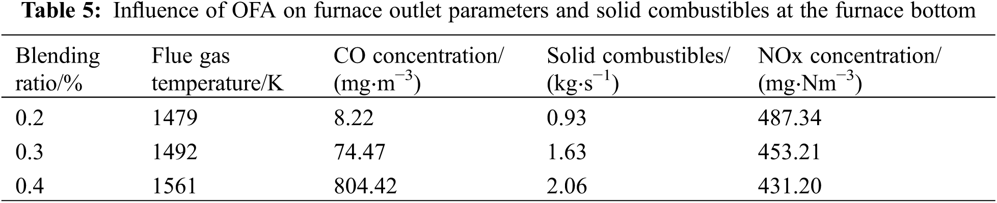
It should be mentioned that the high reducing atmosphere causes the ash melting point to decline, aggravating the occurrence of furnace coking phenomenon. Thus, the OFA coefficient should be chosen reasonably for large blending ratios. Considering the combustion properties and pollutant emissions in the furnace (Table 5), the OFA coefficient of 0.2 is recommended for the sludge blending ratio of 40%.
3.3 Effect of Blending Ratio under Different Loads
Fig. 8 illustrates the influence of the blending ratio on the average flue gas temperature under different loads. As a load decreases, the average flue gas temperature decreases as well, the position of the flame center moves downwards, and the high-temperature region shrinks, especially at 50% load, while the flue gas temperature decreases noticeably above the main combustion zone. Under the same load, with an increasing blending ratio, the position of the flame center gradually rises, whereas the degree of increase tends to be less evident as the load drops. Because the excess air ratio in the main combustion zone rises as the load drops, the influence of increasing blending ratio on the excess air ratio in the main combustion zone is weakened.
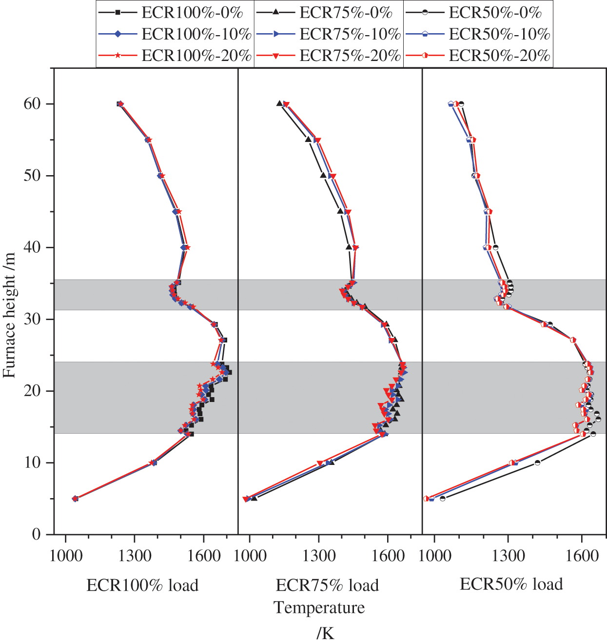
Figure 8: Effect of blending ratio on temperature field under different loads
As the boiler load drops, the influence of increasing blending ratio on the flue gas temperature in the main combustion zone is enhanced. As shown in Fig. 8, the average flue gas temperature at the cross-section of burners is reduced by 30 K for a 20% blending ratio at full load compared with Case 1, while at 50% load, the average flue gas temperature is reduced by 60 K. The reason is that the overall flue gas temperature in the furnace decreases as the load drops while the excess air ratio in the main combustion zone increases, causing a reduction in the heat capacity. Hence, the effect of the heating value variation on the flue gas temperature is more noticeable at low loads.
Fig. 9 compares the representative parameters in the furnace and the mass of solid combustible under various operating conditions, in which the horizontal coordinate indicates a blending ratio at a load, e.g., 100%–20% meaning a blending ratio of 20% at 100% load. From Fig. 9a, it is found that under the same load levels, with an increasing blending ratio, the outlet flue gas temperature displays, first a decreasing, followed by increasing variations. The outlet flue gas temperature is the lowest at a 10% blending ratio, which is due to the low blending ratio improving the combustion of blended fuel. When further increasing the blending ratio, the delayed combustion leads to the increase regarding the flame center, which is undoubtedly a benefit for ensuring the inlet flue gas temperature of the denitrification reactor under low loads.
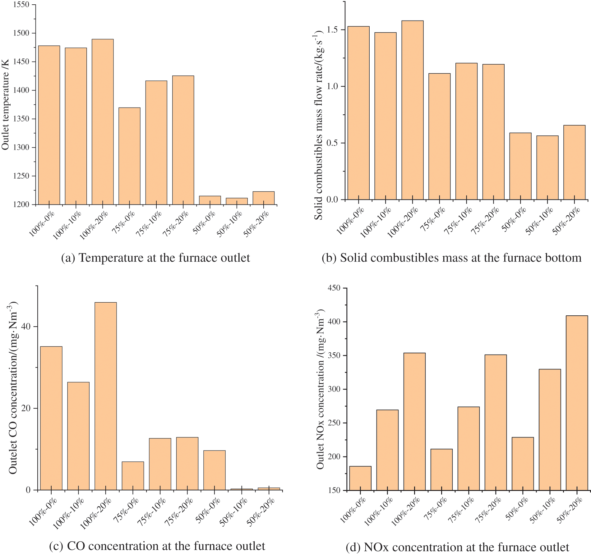
Figure 9: Comparison of furnace outlet parameters and solid combustibles for different operations
Figs. 9b and 9c show the variation in solid combustible mass and the CO concentration under different cases. It is shown that the solid combustible mass and the CO concentration decrease significantly with the load. As the load drops, the excess air ratio in the main combustion zone increases, and the CO concentration decreases. Additionally, the supporting role of the secondary air in the main combustion zone is enhanced, leading to a reduction of solid combustibles mass. Fig. 9d shows that the overall NOx concentration increases as the blending ratio increases. Under the same loads, the NOx concentration increases, and the increment is more evident under low loads. For the same blending ratio, the NOx concentration increases with dropping the load. The reasons include: (1) as the load drops, the average flue gas temperature in the main combustion zone reduces, and the amount of fuel NOx produced decreases. But for 50% load, with increasing the excess air ratio, the oxygen content in the main combustion zone significant increases, leading to the accelerated generation of fuel NOx; (2) with increasing the blending ratio, the combustion is delayed, and the flame center moves upwards, leading to weakening the fuel-staged combustion, and the ability to inhibit NOx production in the burnout zone decreases; and (3) the nitrogen content of the dried sludge is high and increasing the blending ratio results in a significant increase in the fuel NOx generation in the main combustion zone.
The influence of the blending ratio of sludges on the coal burnout rate in the furnace is complicated. When the blending ratio is low, increasing the blending ratio enhances the burnout of bituminite; an additional increase in the blending ratio deteriorates the combustion of blended fuel, leading to an increase in CO concentration at the furnace outlet. The mass of solid combustible at the bottom of the furnace chamber can be effectively reduced by appropriately raising the secondary airflow below the operating-layer burners.
An annular high-temperature region is formed at the cross-section of burners, and the temperature at the center is low, indicating a reasonable pattern of the tangential combustion mode. With increasing the blending ratio or dropping the load, the temperature at the cross-section of burners decreases, and the high-temperature region gradually shrinks toward the burner nozzles. On the other hand, as the OFA coefficient is raised, the flue gas temperature at the cross-section of burners reduces significantly, and the high-temperature region in the vicinity of burners is lessened.
For a large blending ratio under full load, reducing the OFA coefficient can effectively increase the average flue gas temperature in the main combustion zone and significantly improve the burnout rate at the furnace outlet. However, the air-staged combustion is weakened, and the NOx concentration at the furnace outlet increases. A high OFA coefficient causes a significant increase in the temperature above the furnace, leading to a possible high-temperature slagging or tube bursting of superheaters. Considering the influence of the OFA coefficient on the combustion and pollutant emissions in the furnace, the OFA coefficient of 0.2 is preferred in practical applications.
Under the full load, the average flue gas temperature in the main combustion zone decreases as the blending ratio increases, while the oxygen, CO concentration, and NOx concentrations are reduced. For a blending ratio of 40% under full load, the increment of flue gas temperature at the furnace outlet is not notable. Hence, from the combustion point of view, it is feasible to blend a large proportion of dried sludges together. The temperature in the main combustion zone decreases more obviously at low loads than at high loads, which is not beneficial to the stable combustion, but can increase the flue gas temperature at the furnace outlet, thereby ensuring the safe operation of the denitrification system. When the nitrogen content of dried sludge is high, increasing the blending ratio leads to a significant increase in fuel NOx generation in the main combustion zone. For a practical operation, a low nitrogen content sludge is suggested when blending a large percentage of dried sludges in furnaces.
Funding Statement: The authors received no specific funding for this study.
Conflicts of Interest: The authors declare that they have no conflicts of interest to report regarding the present study.
References
1. Hu, Y. J., Zheng, X. Y., Ning, F. Y. (2013). Analysis on energy balance and reaction heat of sewage sludge pyrolysis process. Journal of Chinese Society of Power Engineering, 33(5), 399–404. [Google Scholar]
2. Vesilind, P. A., Ramsey, T. B. (1996). Effect of drying temperature on the fuel value of wastewater sludge. Waste Management & Research, 14(2), 189–196. DOI 10.1177/0734242X9601400208. [Google Scholar] [CrossRef]
3. Ogada, T., Werther, J. (1996). Combustion characteristics of wet sludge in a fluidized bed. Fuel, 75(5), 617–626. DOI 10.1016/0016-2361(95)00280-4. [Google Scholar] [CrossRef]
4. Tang, Z. J., Cen, C. P., Fang, P. (2012). Thermogravimetric experiment on co-firing characteristics of coal with municipal sewage sludge. Journal of Chinese Society of Power Engineering, 32(11), 878–884. [Google Scholar]
5. Folgueras, M. B., Daz, R. M., Xiberta, J., Prieto, I. (2003). Thermogravimetric analysis of the co-combustion of coal and sewage sludge. Fuel, 82(15–17), 2051–2055. DOI 10.1016/S0016-2361(03)00161-3. [Google Scholar] [CrossRef]
6. Stelmach, S., Wasielewski, R. (2008). Co-combustion of dried sewage sludge and coal in a pulverized coal boiler. Journal of Material Cycles and Waste Management, 10(2), 110–115. DOI 10.1007/s10163-007-0206-9. [Google Scholar] [CrossRef]
7. Kijo-Kleczkowska, A., Środa, K., Kosowska-Golachowska, M., Musiał, T., Wolski, K. (2016). Experimental research of sewage sludge with coal and biomass co-combustion, in pellet form. Waste Management, 53, 165–181. DOI 10.1016/j.wasman.2016.04.021. [Google Scholar] [CrossRef]
8. Pronobis, M. (2006). The influence of biomass co-combustion on boiler fouling and efficiency. Fuel, 85(4), 474–480. DOI 10.1016/j.fuel.2005.08.015. [Google Scholar] [CrossRef]
9. Park, S. W., Jang, C. H. (2011). Characteristics of carbonized sludge for co-combustion in pulverized coal power plants. Waste Management, 31(3), 523–529. DOI 10.1016/j.wasman.2010.10.009. [Google Scholar] [CrossRef]
10. Fang, Q. Y., Huang, L., Yao, B. (2006). Combustion process simulation with duo-mixture fraction/PDF approach of tangentially coal blend fired boilers. Journal of Power Engineering, 26(2), 185–190. [Google Scholar]
11. Zhu, T. Y., Yin, L. B., Zhan, Z. G., Xu, Q. S., Fang, Q. Y. et al. (2016). The adaptability of PDF transport model and eddy-dissipation model in simulation of coal combustion and co-combustion with sludge in a coal-fired boiler. Journal of Central South University (Natural Science Edition), 47(8), 2864–2872. [Google Scholar]
12. Zhang, C., Zhu, T. Y., Yin, L. B., Fang, Q. Y., Zhan, Z. G. et al. (2015). Field test and numerical simulation for co-combustion of sludge in a 100 MW coal-fired boiler. Journal of Combustion Science and Technology, 21(2), 114–123. [Google Scholar]
13. Meng, T., Xing, X. L., Zhang, J., Zhou, L., Zhang, L. et al. (2021). Numerical simulation study on the effect of air distribution on combustion of coal-fired boiler blended with sludge. Clean Coal Technology, 27(1), 263–271. [Google Scholar]
14. Adamczyk, W. P., Werle, S., Ryfa, A. (2014). Application of the computational method for predicting NOx reduction within large scale coal-fired boiler. Applied Thermal Engineering, 73(1), 343–350. DOI 10.1016/j.applthermaleng.2014.07.045. [Google Scholar] [CrossRef]
15. Kharoua, N., Khezzar, L., Alshehhi, M. (2018). The interaction of confined swirling flow with a conical bluff body: Numerical simulation. Chemical Engineering Research and Design, 136, 207–218. DOI 10.1016/j.cherd.2018.04.034. [Google Scholar] [CrossRef]
16. Liang, J., Song, Z., Zhang, P. (2019). An experimental study on fuel combustion under external irradiance. Fluid Dynamics & Materials Processing, 15(4), 445–458. DOI 10.32604/fdmp.2019.07951. [Google Scholar] [CrossRef]
17. Zhou, L., Liang, Y. (2021). Study of the combustion process inside an ethanol-diesel dual direct injection engine based on a non-uniform injection approach. Fluid Dynamics & Materials Processing, 17(1), 159–170. DOI 10.32604/fdmp.2021.010051. [Google Scholar] [CrossRef]
18. Bentarzi, F., Mataoui, A. (2018). Turbulent flow produced by twin slot jets impinging a wall. Fluid Dynamics & Materials Processing, 14(2), 107–120. DOI 10.3970/fdmp.2018.06046. [Google Scholar] [CrossRef]
Cite This Article
 Copyright © 2023 The Author(s). Published by Tech Science Press.
This work is licensed under a Creative Commons Attribution 4.0 International License , which permits unrestricted use, distribution, and reproduction in any medium, provided the original work is properly cited.
 Downloads
 Citation Tools