
 Submit a Paper
 Propose a Special lssue
 Open Access
ARTICLE

Performance of a Solar-Biomass Adsorption Chiller
1 Energy, Water, Environment and Process Laboratory, National School of Engineering of Gabes University of Gabes, Omar Ibn ElKhattab, Gabes, Tunisia
2 National Engineering School of Sfax, Sfax, Tunisia
3 Faculty of Sciences and Technology/UIT Longwy Lab. LERMAB (UdL/INRA/Labex ARBRE), University of Lorraine, Nancy, France
* Corresponding Author: Najeh Ghilen. Email:
(This article belongs to the Special Issue: Materials and Energy an Updated Image for 2021)
Fluid Dynamics & Materials Processing 2023, 19(4), 1015-1026. https://doi.org/10.32604/fdmp.2022.022285
Received 02 March 2022; Accepted 17 May 2022; Issue published 02 November 2022
 View Full Text
 Download PDF
Abstract
A dynamic model is presented for a chiller working with a composite adsorbent (silica activated carbon/CaCl2)–water pair in a solar-biomass cooling installation. The main objective is determining a link between two possible evaporator configurations and the refrigerator’s performances. The two considered evaporators work at different pressure levels. The related time evolution profiles of temperature, pressure and water content are studied. Moreover, the effects of hot water inlet temperature and cooling water inlet temperature on the specific cooling capacity (SCP) and coefficient of performance (COP) are predicted by means of numerical simulations. The results show that an increase in the temperature of hot water and a decrease in the temperature of the cooling water allow an increase in COP and SCP. In particular, for a hot water inlet temperature of 85°C and a cooling water inlet temperature of 40°C, the COP and Qev are 0.67 and 4.3 kW, respectively.Keywords
Nomenclature
| A | Heat transfer area, m2 |
| Cp | Specific heat, kJ/kg.K |
| DS0 | Coefficient, m2/s |
| E | Heat exchanger efficiency |
| L | Latent heat of vaporization, kJ/kg |
| m | Masse, kg |
| | Mass flow rate, kg/s |
| ∆H | Isosteric heat of adsorption, kJ/kg |
| P | Pressure, Pa |
| q | Heat, kJ |
| SCP | Specific cooling power, kW/kg |
| t | Time, s |
| T | Temperatures, °C |
| U | Overall conductance, W/m2.K |
| w, w* | Instantaneous Uptake, Equilibrium uptake, kg de réfrigérant/kg d’adsorbant |
| COP | Coefficient of performance of the machine |
| Subscripts | |
| a | Adsorbent (silica gel) |
| ad | Adsorber |
| ads | Adsorption |
| cd | Condenser |
| cycle | Cycle |
| ev | Evaporator |
| de | Desorber |
| f | Coolant |
| in | Inlet |
| j | Coolant indice |
| max | Maximum |
| min | Minimum |
| num | Numerical |
| out | Outlet |
| r | Refrigerant |
| r,v | Refrigerant vapor |
| v | Vapor |
During the last decades, we are witnessing a large, generalized and even more accentuated energy deficit in developing countries. Noble energies are mainly produced by fossil sources which not only are gradually depleted but also have harmful environmental consequences: pollution of the atmosphere, destruction of the ozone layer, production of greenhouse gases contributing to the global warming. The current trend is therefore to find new forms of energy from renewable sources to overcome this problem. The ideal would be to produce all the energy used by renewable sources, but unfortunately this sector still faces many technological and commercial challenges.
The increasing demand of the air conditioning pulled a significant increase of the demand of the primary energy resources. Adsorption refrigeration systems are one of the processes which can be fed using renewable energies. Several works in the field of adsorption chiller have been successfully realized.
The purpose of which to survey the performance evaluation parameters of adsorption cooling systems such as coefficient of performance and specific cooling power. Optimization methods for improving the performance of a refrigeration system by adsorption. Among these factors, adsorption refrigeration pairs is the most important role for system performance, and the development of another type of adsorbent (composite adsorbent) to improve system performance [1–6].
Improving system performance involves improving mass and heat transfer by increasing the adsorption rate, subsequently improving COP and SCP, and since the adsorbent bed is the heart of the machine. adsorbent bed configuration and Adsorbent are the keys to improvement for this fact several adsorbent have been tested and several configuration are studied.
Many configuration of adsorption systems with different pairs have been studied in the literature for refrigeration application, a new adsorption pair AlPO4-34/water is synthesized by Kim et al. [7]. WSS impregnated with 20 wt% LiCl has been used as an adsorbent was experimentally developed by He et al. [8] with heat recovery scheme.
In order to provide maximum efficiency under specified operating conditions [9–11] a two, three and four beds are numerically studied heat and mass recovery. Performance can also be improved on the heat transfer inside the bed by studying the effect of fin design parameters. A decreasing of the fin spacing enhances the heat transfer significantly. The fin thickness has a less effect on heat transfer inside the bed [12]. And the effect of various geometry on the coefficient of performance (COP) and specific cooling power (SCP) and of solar adsorption chiller [13] can also be a way of improving performance.
The objective of this paper is to improving the performance of a refrigeration system by solar-biomass adsorption by using an composite adsorbent, which presents a mixture of silica gel, activated carbon and of chloride of calcium with the percentage following 10% activated carbon, 30% CaCl2 and 60% silica gel in order to maximizing cooling power.
2 Description of the Adsorption System
Fig. 1 shows the schematic diagram of the adsorption refrigeration system with solar/biomass coupling. The system is composed of three main components: solar heating system allowing the heating of water inside the storage tank, a biomass gasification boiler and adsorption refrigerator with two evaporators and two beds filled with adsorbents.
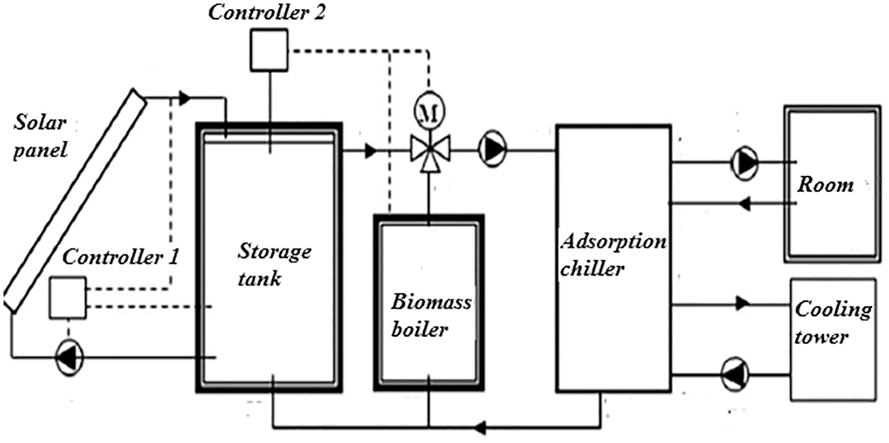
Figure 1: Diagram of cold production by solar-biomass coupling
The collectors absorb solar energy to heat the heat transfer fluid, which is then pumped to a storage tank. The biomass boiler is located between the adsorption chiller and the hot water storage tank. The boiler is considered as an additional source; in case of lack of sun or if solar energy is insufficient. It is controlled by a controller and heats the water entering the refrigerator. The refrigerator consists of two beds and two evaporators operating with the pair (silica/activated carbon/CaCl2)–water. The heat required for desorption is drawn from hot water coming from the storage tank heated with solar energy or biomass. While the cooling circuits is supplied by the cooling tower. Chilled water produced by the refrigerator provides comfort conditions through the room fan coil.
3 Operation of the Adsorption Chiller
The diagram of the refrigerator with double evaporator is drawn in Fig. 2. The refrigerator consists of two evaporators, two beds full of adsorbent, and a condenser. During a cycle, each adsorbent bed undergoes four processes: preheating, desorption, pre-cooling, low pressure adsorption. One of the adsorbent beds plays the role of a desorber; it is heated by hot water coming from the storage tank then it is connected to the condenser. The water vapor is then desorbed and passes to the condenser, where it condenses and is then sent to the low pressure evaporators.
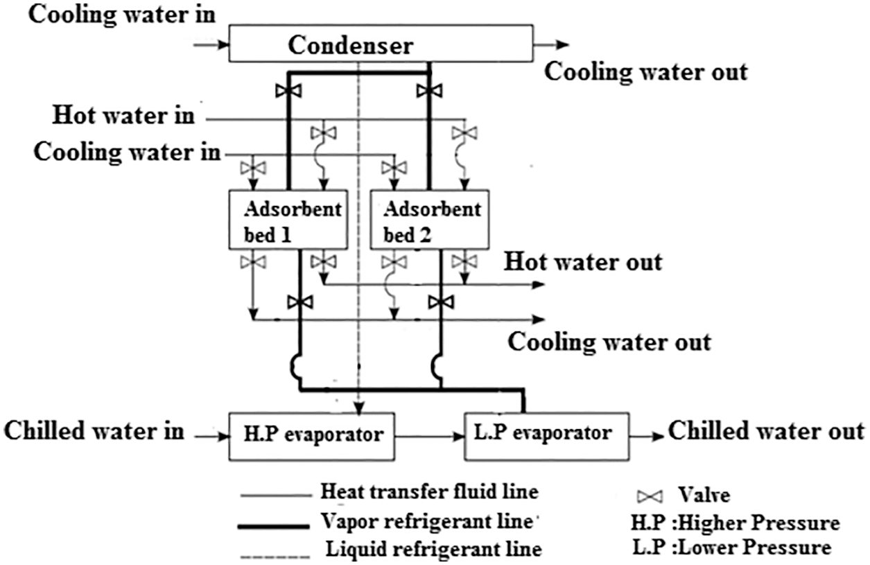
Figure 2: The schematic of the adsorption refrigeration system
After the adsorbent bed is cooled by the cooling water to decrease the temperature levels and subsequently its pressure to connect with the low pressure evaporator in the next step. Then the adsorbent bed is linked to the low pressure evaporator allowing low pressure adsorption. The chilled water first enters the high pressure evaporator and then passes through the low pressure evaporator. The water in the evaporator evaporates and the vapor is adsorbed by the adsorbent, (Fig. 3) and a new cycle begins. The two-stage cooling allows the chilled water to have a larger heat transfer fluid temperature difference between inlet and outlet, such as ΔT = 7°C, compared with that of the single-stage adsorption chiller (ΔT = 5°C). The large temperature difference has the effect of reducing the power of the pump.
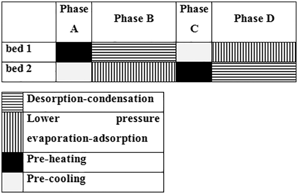
Figure 3: The operation time of the adsorption refrigeration system
4.1 Rate of Desorption/Adsorption
The rate of desorption or adsorption is calculated using the linear driving force kinetic equation. The coefficients of this equation for the silica activated carbon/CaCl2)–/water couple are determined by Chihara et al. [14] and are presented below:
The effective mass transfer coefficient inside the pores Ks is given by:
The effective diffusivity is defined as follows:
where:
Dso = 2.54 × 10⁻⁴ m2/s, RP = 1.7 × 10⁻⁴ m, Ea = 4.2 × 10⁴ J/mol, F0 = 15, R = 8,314 J/mol K.
The equilibrium uptake of adsorbent pair is estimated using the equation developed by Boelman et al.[15].
where Ps is the corresponding saturation vapor pressure of the refrigerant. Ps for water vapor is determined by the following equation:
4.2 Energy Balance of Adsorber
The adsorption energy balance is described by:
The outlet temperature of cooling water can be expressed as:
4.3 Energy Balance of Desorber
The desorption energy balance is described by:
The outlet temperature of hot water can be expressed as:
4.4 Energy Balance of Condenser
The condenser energy balance equation can be written as:
The outlet temperature of cooling water can be expressed as:
4.5 Energy Balance of Evaporator
The energy balance in the evaporator is expressed as:
The outlet temperature of chilled water can be written as:
4.6 Mass Balance in the Evaporator
The mass balance for the refrigerant can be expressed by neglecting the gas phase is:
where, ma is the adsorbent mass.
System performance equation
The COP value is defined by the following equation:
The cooling capacity of the system is expressed by:
where:
Specific Cooling Power
where:
ma = 50 Kg,
Ca = 0.930 kJ/kg.K, Cpr = 4.18 kJ/kg.k,
Fig. 4 shows the experimental and numerical temperature profiles of hot, cooling and chilled water for a two-bed adsorption chiller as a function of time for duration of 840 s, a good agreement between the experimental and numerical results is noticed. The validation of the model is carried out for cooling with aerothermal. The adsorbent bed presents the central element and the heart of the adsorption machine, a validation of the global model is necessary to determine the thermo-physical conditions allowing the improvement of the performance.
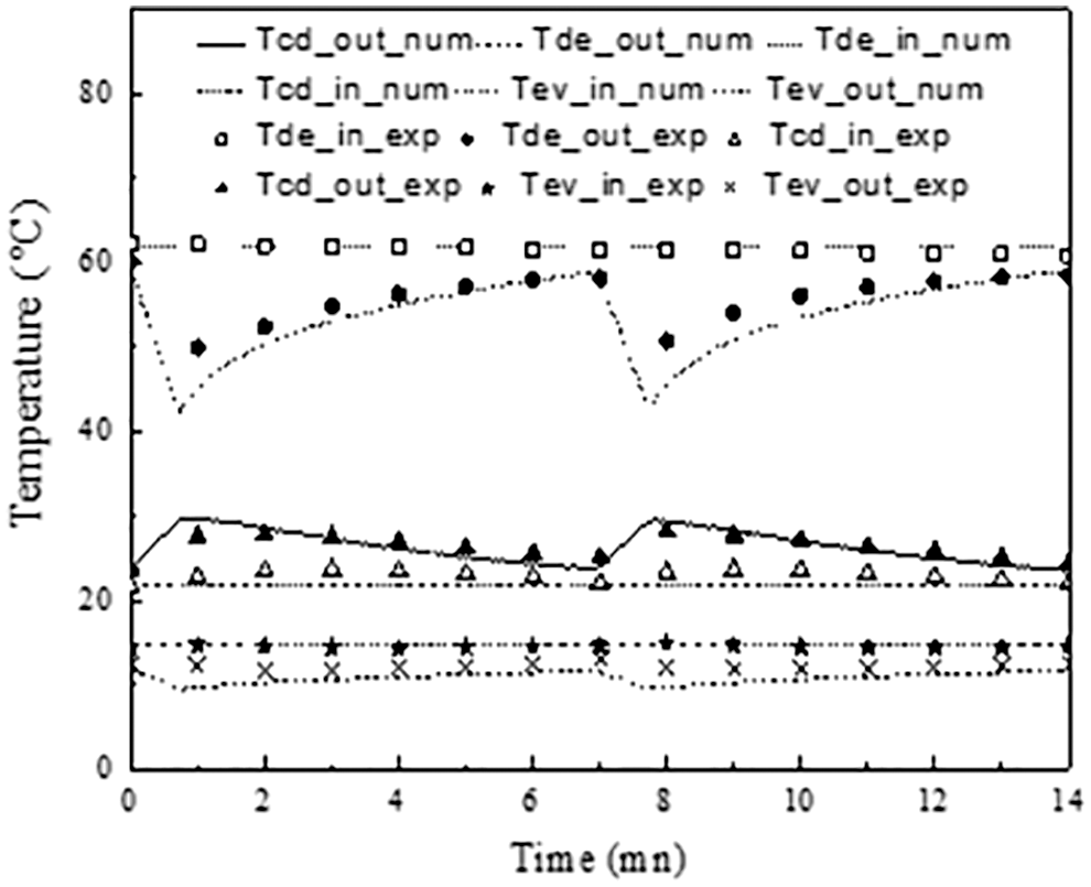
Figure 4: Overall outlet temperature profile of heat transfer fluid for two beds adsorption chiller
5.2 Analysis on the Performance of the Proposed System
Fig. 5 shows the inlet temperature of chilled water, the outlet temperature of the higher pressure evaporator, and the outlet temperature of the lower pressure evaporator.
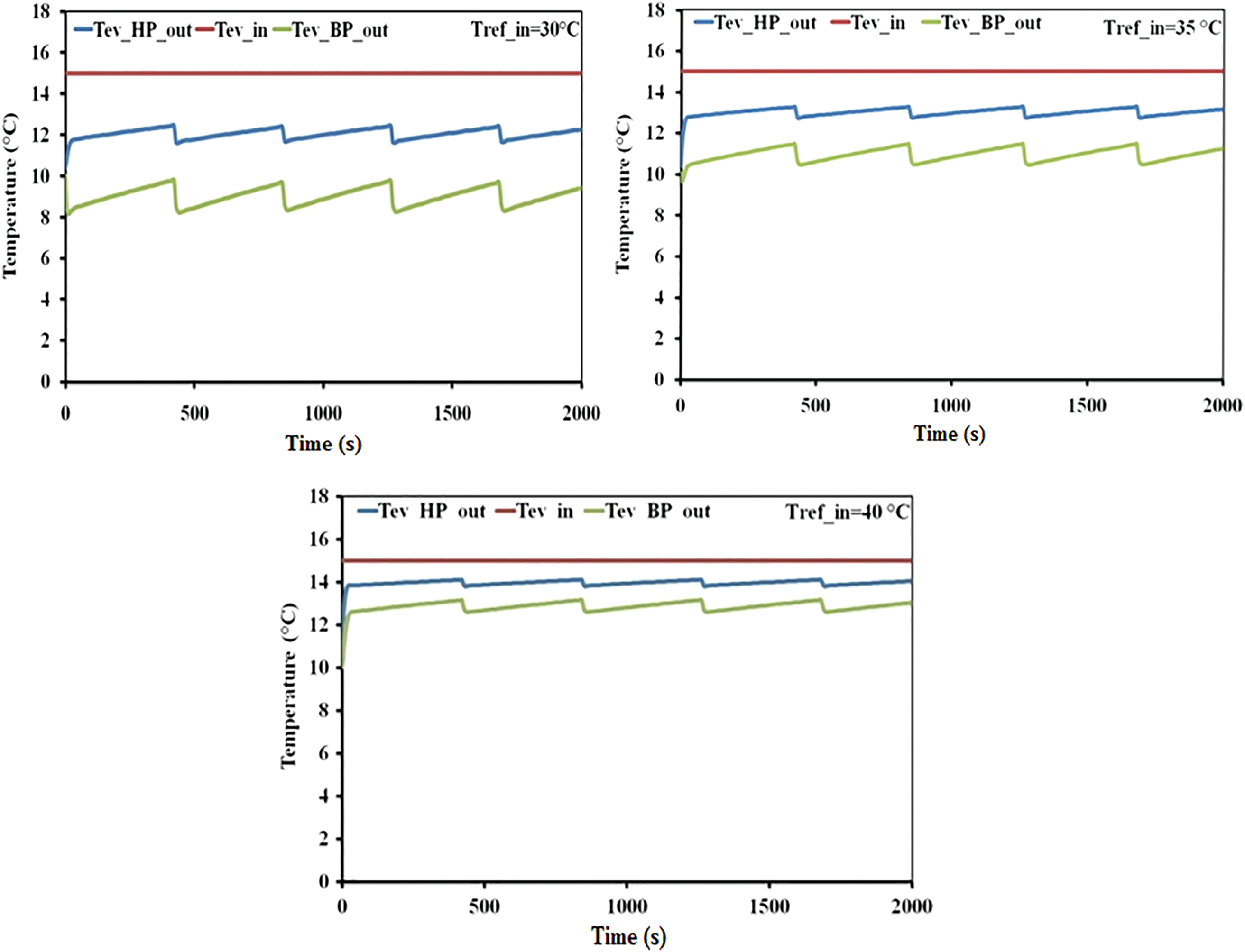
Figure 5: Chilled water temperature profiles of a refrigeration cycle with two adsorbent beds, dual evaporators
The chilled water (heat transfer medium at the evaporator) was cooled first from 18°C to about. 14°C–15°C by the higher pressure evaporator, then it is cooled again to approx. 11°C–12°C by the lower pressure evaporator.
Cold water outlet temperature peaks were observed around 450, 870, 1290, and 1710 s, during which the adsorbent bed (the adsorbent) was in the pre-cooling phase.
There is no evaporation of the refrigerant in the evaporator during the pre-cooling which leads to the increase of the cold water temperature. The serial flow of cold water causes a small lag between the peak outlet temperatures of the two evaporators.
The water content and the temperature of the adsorbent beds under the operating conditions mentioned above are shown in Fig. 6.
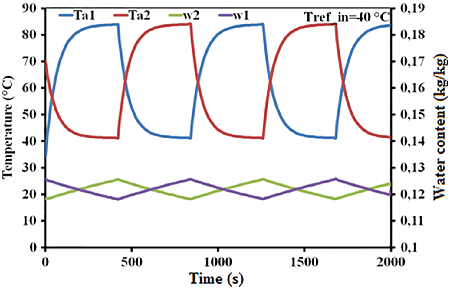
Figure 6: Temperature variation of the two adsorbent beds and water content of the two beds as a function of time of a refrigeration cycle with two adsorbent beds, double evaporators
The water content of the adsorbent has been reduced, During the first 420 s, to approximately 0.12 kg/kg during the desorption phase, Once the desorption is complete, the temperature of the adsorbent bed approaches thathot water inlet temperature. the adsorbent bed is pre-cooled for a period of 40 s, and its temperature decreases to approximately 55°C. Then the low pressure adsorption starts and the adsorbent bed is connected to the low pressure evaporator. The adsorbent bed 2 was cooled with the cooling tower, and at the end of the low pressure adsorption process, the water content of the adsorbent bed 2 increased by about 0.118 kg/kg. At 700 s, to start the low pressure adsorption process and the adsorbent bed 2 is connected to the low pressure evaporator which leads to a water content of the adsorbent at around 0.125 kg/kg.
5.3 Effect of Operating Conditions
Fig. 7 shows the variation of the water vapor pressure in the high pressure evaporator and in the low pressure evaporator, the pressure in the high pressure evaporator is between 1.3–1.5 kPa and that of the low pressure evaporator varies between 1.1–1.4 kPa.
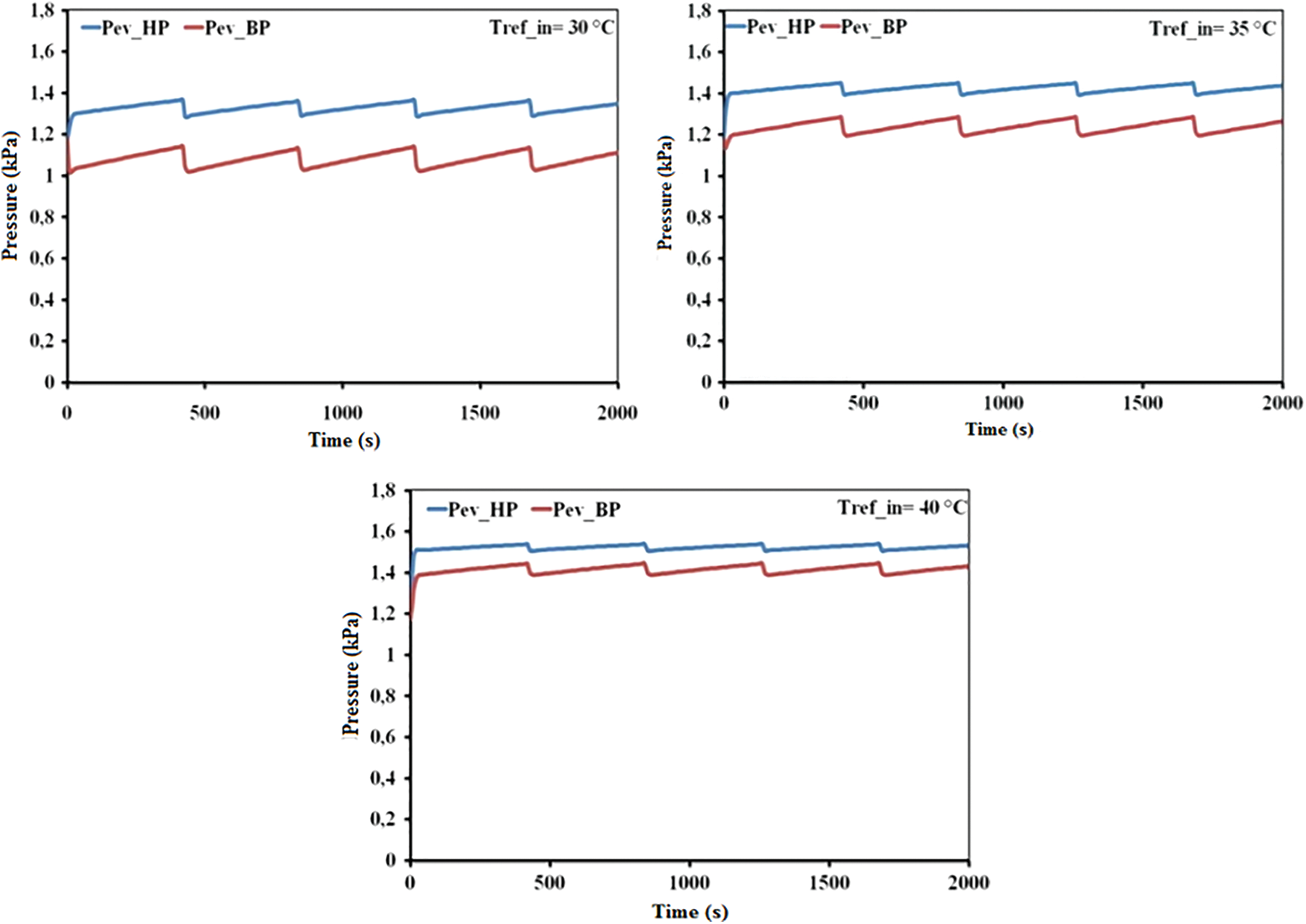
Figure 7: Pressure variation of the two high and low pressure evaporators as a function of time of a refrigeration cycle with two adsorbent beds, double evaporators
Fig. 8 illustrates the variation in cooling capacity as a function of time for the high pressure evaporator and the low pressure evaporator. Note that for a system with two evaporators, the cooling capacity is twice that of a single evaporator.
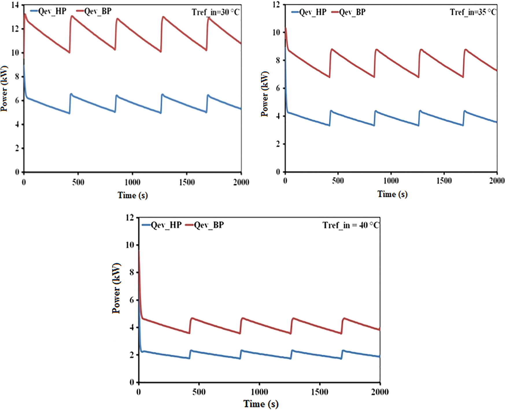
Figure 8: Variation of the cooling capacity of the two high and low pressure evaporators as a function of the time of refrigeration cycle with two adsorbent beds, double evaporators
5.4 Effect of Generation Temperature and Condensing Temperature
Fig. 9 shows the influence of the variation in the condensing temperature on the performance of the machine as a function of the regeneration temperature. By setting the temperature Tev_in to 15°C and varying the regeneration temperature and the cooling temperature, Tde_in and Tref_in, respectively, the system performance is an increasing function of the regeneration temperature. The system coefficient of performance (COP) as well as the quantity of cold produced decreases following the increase in the condensing temperature, this can be explained by the fact that the increase in the temperature Tcd leads to an increase in the pressure of refrigerant saturation at the condensing temperature Ps (Tcd). So the regenerated mass of adsorbate (water) increases, therefore an increase in the cycled mass and subsequently a decrease in the amount of cold produced at the Qev evaporator and in the COP of the chiller.
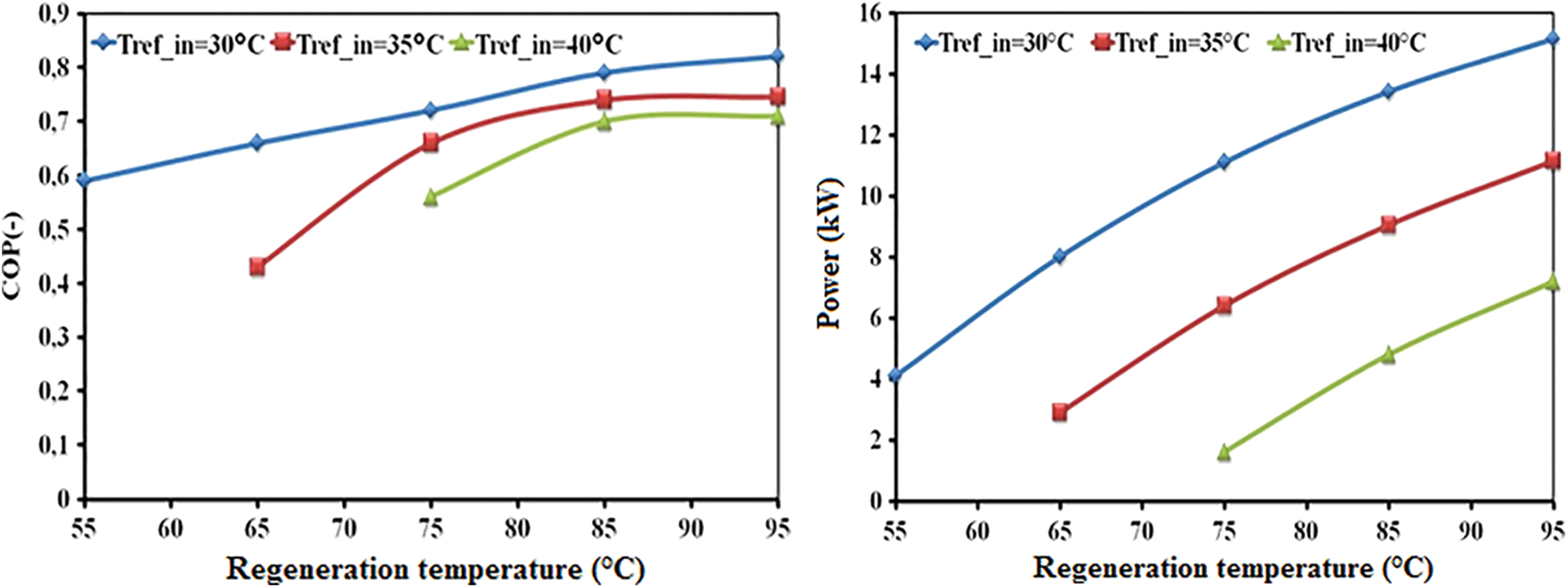
Figure 9: Effect of the regeneration temperature on the COP and the SCP for a variable cooling temperature (Tev_in = 15°C, tcycle = 840 s)
Fig. 10 shows the variation of the cold water temperature obtained as a function of the regeneration temperature for variable cooling water temperatures. We notice a slight variation in the evaporator outlet temperature with the heating water temperature and a decrease following the increase in the condensing temperature for a fixed evaporator inlet temperature Tev_in.
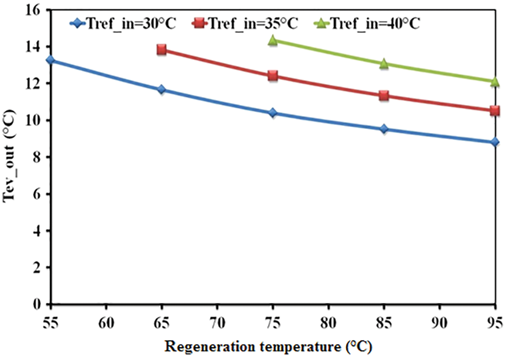
Figure 10: Effect of the regeneration temperature on the evaporator outlet temperature for a variable cooling temperature (Tev_in = 15°C, tcycle = 840 s)
In this paper, we have studied a two element adsorption system with double evaporator. Good performance is obtained with this design. The effect of the operating conditions (hot water temperature, cooling water temperature) on the performance of the system is made in order to improve them. The results of the simulations show that the coefficient of performance (COP) and the specific cooling power (SCP) of the adsorption cooler are highly dependent on the generation temperature. It is observed that an increase in the temperature of hot water and a decrease in the temperature of the cooling water allow an increase in COP and SCP, has a best performance at large temperature difference between inlet and outlet chilled water temperature, also, The biomass boiler makes it possible to keep a constant desorber heating temperature, which facilitates the sizing of the installation for a well-defined energy requirement.
Funding Statement: The authors received no specific funding for this study.
Conflicts of Interest: The authors declare that they have no conflicts of interest to report regarding the present study.
References
1. Benelmir, R., Ghilen, N., El Ganaoui, M., Descieux, D., Gabsi, S. (2014). Technology platform ENERBAT-Gas cogeneration, solar heating and cooling. International Journal of Thermal and Environmental Engineering, 7, 79–85. [Google Scholar]
2. Ghilen, N., Gabsi, S., Messai, S., ElGanaoui, M., Benelmir, R. (2016). Performance of silica gel-water solar adsorption cooling system, case studies in thermal engineering. Case Studies in Thermal Engineering, 8, 337–345. DOI 10.1016/j.csite.2016.07.002. [Google Scholar] [CrossRef]
3. Ghilen, N., Gabsi, S., Benelmir, R., ElGanaoui, M. (2017). Performance simulation of two-bed adsorptionrefrigeration chiller with mass recovery. Journal of Fundamentals of Renewable Energy and Applications, 7(3), 41–49. DOI 10.4172/2090-4541.1000229. [Google Scholar] [CrossRef]
4. Ghilen, N., Messai, S., Gabsi, S., ElGanaoui, M., Benelmir, R. (2017). Performance simulation of two-bed silica gel-water adsorption chillers. Global Journal of Researches in Engineering: Journal of General Engineering, 17, 41–49. [Google Scholar]
5. Ghilen, N., Messai, S., Gabsi, S., El Ganaoui, M., Benelmir, R. (2017). Numerical investigation of silica gel-water solar adsorption cooling system with simulink. American Journal of Applied Sciences, 14(8), 786–794. DOI 10.3844/ajassp.2017.786.794. [Google Scholar] [CrossRef]
6. Ghilen, N., Gabsi, S., Benelmir, R., ElGanaoui, M. (2021). Experimental analysis of a solar adsorption system refrigeration cycle with silica-gel/water pair. Journal of Fundamentals of Renewable Energy and Applications, 11(1), 7–18. [Google Scholar]
7. Kim, S., Cho, K., Jong, K. N., Beum, T., Yoon, C. et al. (2020). Improvement of cooling performance of water adsorption chiller by using aluminophophate adsorbent. Microporous and Mesoporous Materials, 309, 110572. DOI 10.1016/j.micromeso.2020.110572. [Google Scholar] [CrossRef]
8. He, F., Nagano, K., Togawa, J. (2020). Experimental study and development of a low-cost 1 kW adsorption chiller using composite adsorbent based on natural mesoporous material. Energy, 209(22), 118365. DOI 10.1016/j.energy.2020.118365. [Google Scholar] [CrossRef]
9. Muttakin, M., Islam, A., Malik, K., Pahwa, D., Saha, B. (2020). Study on optimized adsorption chiller employing various heat and mass recovery scheme. International Journal of Refrigeration, 126, 222–237. DOI 10.1016/j.ijrefrig.2020.12.032. [Google Scholar] [CrossRef]
10. Rouf, R. A., Jahan, N., Alam, K. C. A., Sultan, A. A., Saha, B. B. et al. (2020). Improved cooling capacity of a solar heat driven adsorption chiller. Case Studies in Thermal Engineering, 17, 100568. DOI 10.1016/j.csite.2019.100568. [Google Scholar] [CrossRef]
11. Thomas, R., Srinivas, G. (2020). A centrally heated, air-coupled adsorption cooling system driven by waste heat. International Journal of Refrigeration, 120, 58–65. DOI 10.1016/j.ijrefrig.2020.08.026. [Google Scholar] [CrossRef]
12. Mahmoud, M., Abd, E., Ahmed, M. (2020). Effect of fin design parameters on the performance of a two-bed adsorption chiller. International Journal of Refrigeration, 113, 164–173. DOI 10.1016/j.ijrefrig.2020.01.006. [Google Scholar] [CrossRef]
13. Jalil, E., Goudarzi, K. (2020). Effect of adsorbent configuration on performance enhancement of continuous solar adsorption chiller with four quadric parabolic concentrators. Renewable Energy, 158(5), 360–369. DOI 10.1016/j.renene.2020.05.138. [Google Scholar] [CrossRef]
14. Chihara, K., Suzuki, M. (1983). Air drying by pressure swing adsorption. Journal of Chemical Engineering of Japan, 16(4), 293–299. DOI 10.1252/jcej.16.293. [Google Scholar] [CrossRef]
15. Boelman, C., Saha, B., Kashiwagi, T. (1995). Computer simulation of a silica gel-water adsorption refrigeration cycle—The influence of operating conditions of cooling output and COP. ASHRAE Transactions, 101, 348–355. [Google Scholar]
Cite This Article
 Copyright © 2023 The Author(s). Published by Tech Science Press.
This work is licensed under a Creative Commons Attribution 4.0 International License , which permits unrestricted use, distribution, and reproduction in any medium, provided the original work is properly cited.
 Downloads
 Citation Tools