
 Submit a Paper
 Propose a Special lssue
 Open Access
ARTICLE
Experimental Analysis of the Flow Characteristics of an Adjustable Critical-Flow Venturi Nozzle
1 Cooperative Innovation Center of Unconventional Oil and Gas (Ministry of Education & Hubei Province), Yangtze University, Wuhan, 430100, China
2 Hubei Oil and Gas Storage and Transportation Engineering Technology Research Center, Wuhan, 430100, China
3 Key Laboratory of Drilling and Production Engineering for Oil and Gas, Wuhan, 430100, China
4 Siji Petroleum Machinery Company, SINOPEC, Jingzhou, 434000, China
5 Petroleum Engineering Technology Research Institute of Shengli Oilfield Company, SINOPEC, Dongying, 257000, China
* Corresponding Author: Xingkai Zhang. Email:
Fluid Dynamics & Materials Processing 2023, 19(3), 755-766. https://doi.org/10.32604/fdmp.2022.021868
Received 10 February 2022; Accepted 20 July 2022; Issue published 29 September 2022
 View Full Text
 Download PDF
Abstract
The response of an adjustable critical-flow Venturi nozzle is investigated through a set indoor experiments aimed to determine the related critical flow rate, critical pressure ratio, and discharge coefficient. The effect of a variation in the cone displacement and liquid content on the critical flow characteristics is examined in detail and it is shown that the former can be used to effectively adjust the critical flow rate. The critical pressure ratio of the considered nozzle is above 0.85, and the critical flow control deviation of the gas flow is within ±3%. Liquid flow can reduce the gas critical mass flow rate accordingly, especially for the cases with larger liquid volume and lower inlet pressure. The set of results and conclusions provided are intended to support the optimization of steam injection techniques in the context of heavy oil recovery processes.Keywords
Steam injection is a significant development method for heavy oil recovery [1–3]. In the steam injection process, the steam generated by one boiler is often injected into multiple steam injection wells through branch pipes that are in a parallel relationship. When a conventional regulating valve is used to regulate the flow of one branch, the other branches will also be interfered with, making it difficult for each well to be injected at its own designed flow [4–7]. Therefore, the critical flow nozzles are often used to control the steam flow rate of each injection well [8–10]. There are two main ways to adjust the flow rate through the traditional fixed critical flow nozzle, if necessary. One is to adjust the inlet pressure [11,12], while the other is to change the nozzle throat size [13,14]. However, it is not economical to adjust the steam parameters. In addition, the operation will be complicated when the nozzle throat size is changed by replacing nozzles with different throat diameters or installing multiple nozzles in parallel [15].
Many scholars have conducted in-depth researches on the adjustable critical flow nozzle. Kim et al. [16] have verified the effectiveness of a variable critical nozzle with a replaceable cylindrical rod being inserted into the critical venturi nozzle, and studied its discharge coefficient using a single gas flow. Yanagihara et al. [17] have designed an adjustable venturi nozzle with an adjusting cone. The adjusting cone is placed in the contraction part of the venturi and can move axially under the drive of a stepper motor to change the effective cross-sectional area. Another type of adjustable venturi nozzle designed by Yanagihara et al. [18] consists of a slidable venturi nozzle and a fixed cone. Driven by a stepper motor, the slidable venturi nozzle can move back and forth to change the throat area. Zhang et al. [19] have summarized the implementation of the adjustable critical flow venturi nozzle. However, in the existing literature, the study of the critical flow characteristics of adjustable venturi nozzles, especially the analysis about the critical flow characteristics of gas-liquid two-phase flow through adjustable critical flow venturi nozzles, is scarce.
In view of the above problems, this paper studies the flow characteristics of single-phase air and air-water two-phase flow through an adjustable critical flow venturi nozzle through laboratory experiments. The conclusions of this research may be beneficial for controlling and regulating the steam rate and delivering the predetermined rate to each injection well by using adjustable critical flow venturi nozzles.
2 Structure and Working Principle of the Adjustable Critical Flow Venturi Nozzle
Fig. 1 shows the designed adjustable critical flow venturi nozzle that consists of a fixed critical flow venturi nozzle, an adjusting cone, brackets, a worm gear, and sealing structures. The position of the adjusting cone is changed by the worm gear, thereby changing the effective flow area of the throat of the critical flow venturi nozzle to achieve the purpose of adjusting the critical flow of steam. The worm gear should be set to a sufficiently large distance from the venturi nozzle to reduce the influence on the flow characteristics. It should be noted that Fig. 1 only schematically shows an adjustment method using a worm gear, and it is not the necessary adjustment method that we will ultimately choose for the actual application product. A reasonable adjustment structure and its installation location is a work we will study in the future.
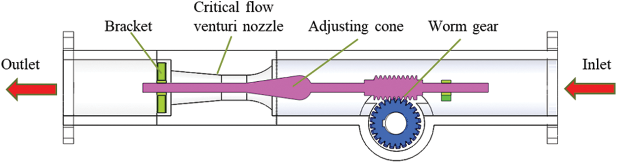
Figure 1: Schematic diagram of the adjustable critical flow venturi nozzle
The structural dimensions of the venturi nozzle and the adjusting cone are shown in Fig. 2. The throat of the venturi nozzle is 27 mm in diameter and length; the constricted section is a torus with a radius of curvature of 40.5 mm; the diffusion section is a frustum cone with a diffusion angle of 5° and a length of 54 mm. The adjusting difficulty increases as the cone angle α of the adjusting cone become greater. However, if α is too tiny, the size of the adjustable critical flow venturi nozzle will be too large. Therefore, the cone angle of the adjusting cone we have designed is 16°, and the effective length of the adjusting cone is 57.35 mm.
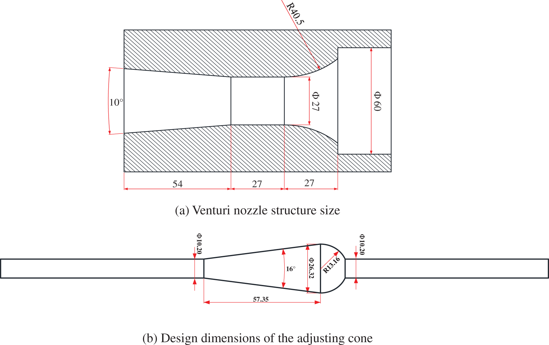
Figure 2: The structural dimensions of the venturi nozzle and the adjusting cone (The unit of length in the figure is millimeters)
During the experiment, the relationship between the critical flow rate of the nozzle and the inlet pressure, the displacement of the adjusting cone, and the water content are tested by using air and tap water as working fluids. Fig. 3a schematically shows the flow loop. The compressed air and tap water flows are measured by a thermal mass flow meter and a Coriolis force flow meter, respectively, and then flow into a static mixer for mixing. After the pressure and temperature of the gas-liquid mixture coming out of the mixer are measured, it enters the test section. In the test section, there is a bypass to facilitate the replacement of the adjustable critical flow venturi nozzle. Pressure sensors are installed at the inlet and outlet of the adjustable critical flow venturi nozzle to measure the inlet pressure and outlet backpressure. A regulating valve is provided downstream of the adjustable critical flow to regulate the backpressure. Both the flow rate of air and tap water can be adjusted by inverters and electric regulating valves. Fig. 3b shows a photograph of the test section.
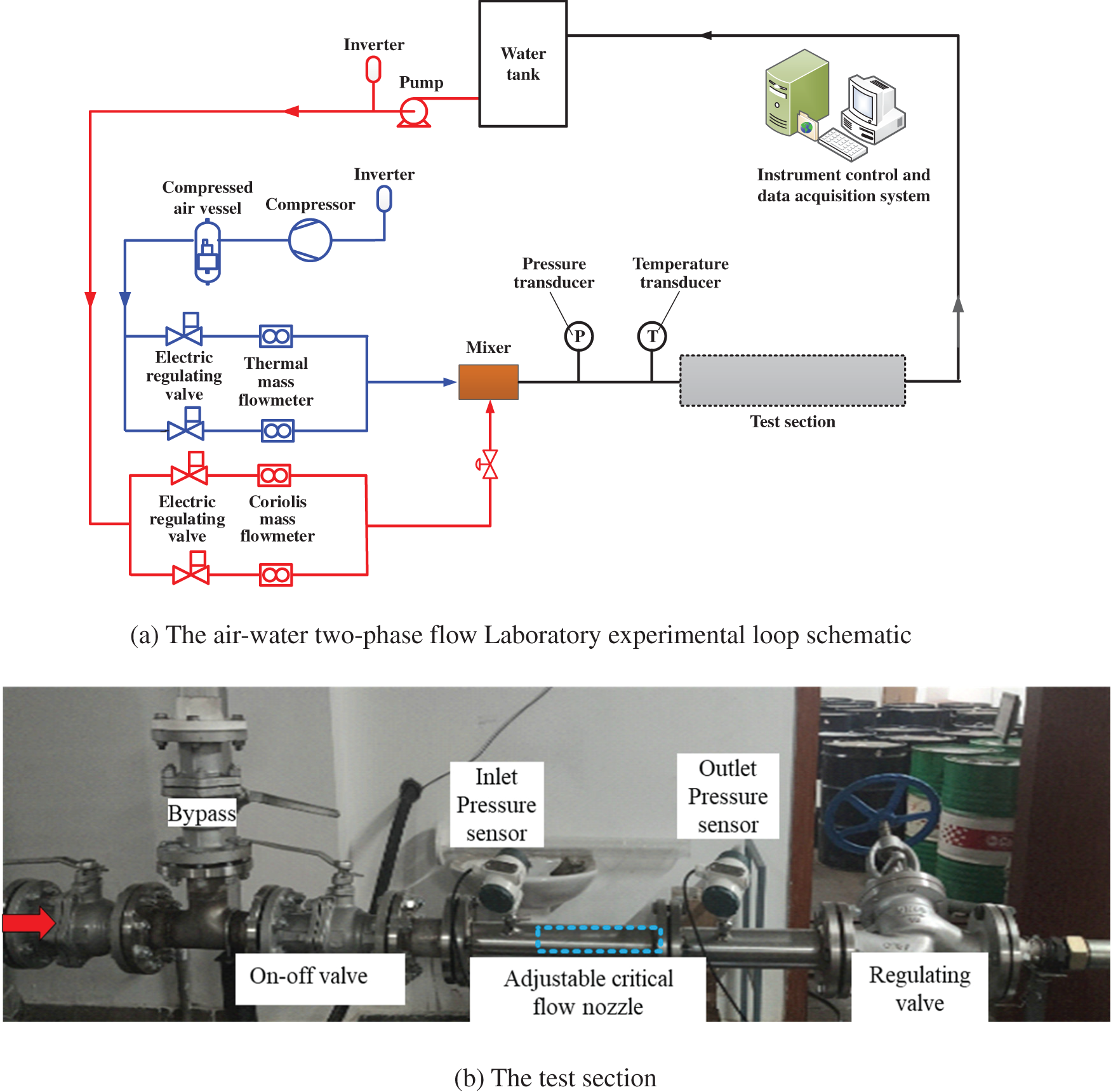
Figure 3: The flow loop and test setup
In the experimental loop, there are two types of E + H thermal gas flowmeters to choose from, depending on the gas flow. Their measurement ranges are 5–400 m3/h and 300–1500 m3/h, respectively, with an uncertainty of 1.5% of the reading. Water is measured by using a Yokogawa AE-115MG electromagnetic flowmeter with an uncertainty of 0.5% in the full range of 0.8–8 m3/h. The pressure of the separated gas has been measured by a Yokogawa FP101A pressure sensor, with a range of 0–1000 kPa and an uncertainty of 0.065% of full scale. The temperature of the separated gas is measured by a thermocouple thermometer with a range of −20°C to 80°C and full-scale uncertainty of 0.2%. During the tests, the signals of the flowmeters, the pressure transducers, and the temperature transducer are directly sampled with an acquisition frequency of 2 kHz and stored on a computer.
In order to accurately determine the relative position of the adjusting cone and the critical flow venturi nozzle, 3D printing is adopted to process them together. This paper studies the adjustable critical flow venturi nozzles with three different adjusting cone displacements of 0 mm, 28.7 mm, and 43.0 mm. The 3D model of the adjustable critical flow venturi nozzle with the adjusting cone displacement of 28.7 mm is shown in Fig. 4a. Fig. 4b shows the photos of the 3D printed adjustable critical flow venturi nozzles.
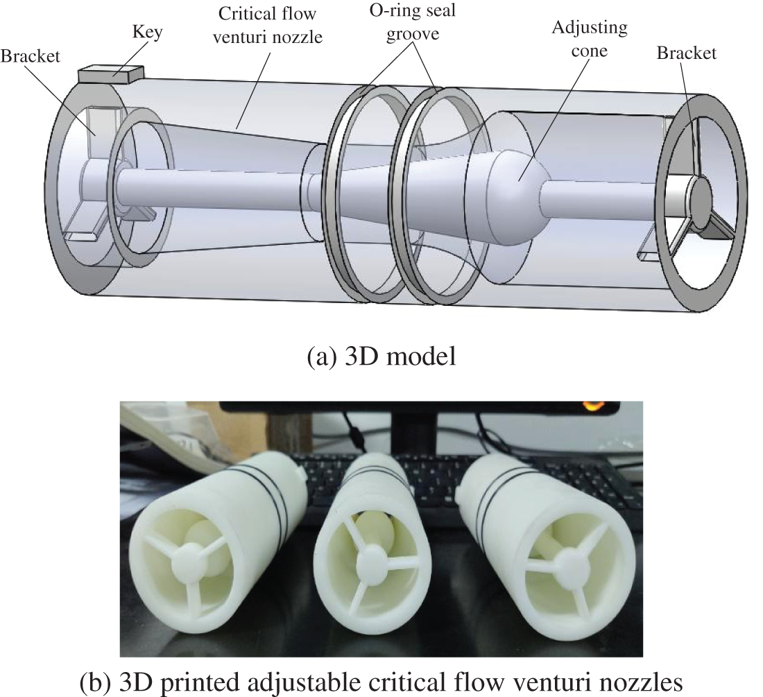
Figure 4: Adjustable critical flow venturi nozzles used in experiments
4 Experimental Results and Analysis
4.1 Relationship between Critical Mass Flow Rate and Inlet Pressure
When only single-phase air flows through the test section, the critical mass flow rate of the adjustable critical flow venturi nozzle varies with the inlet pressure (at this time, the outlet back pressure is maintained at atmospheric pressure), as shown in Fig. 5. In the figure, the abscissa represents the square root of the inlet pressure, and the ordinate is the critical mass flow rate.
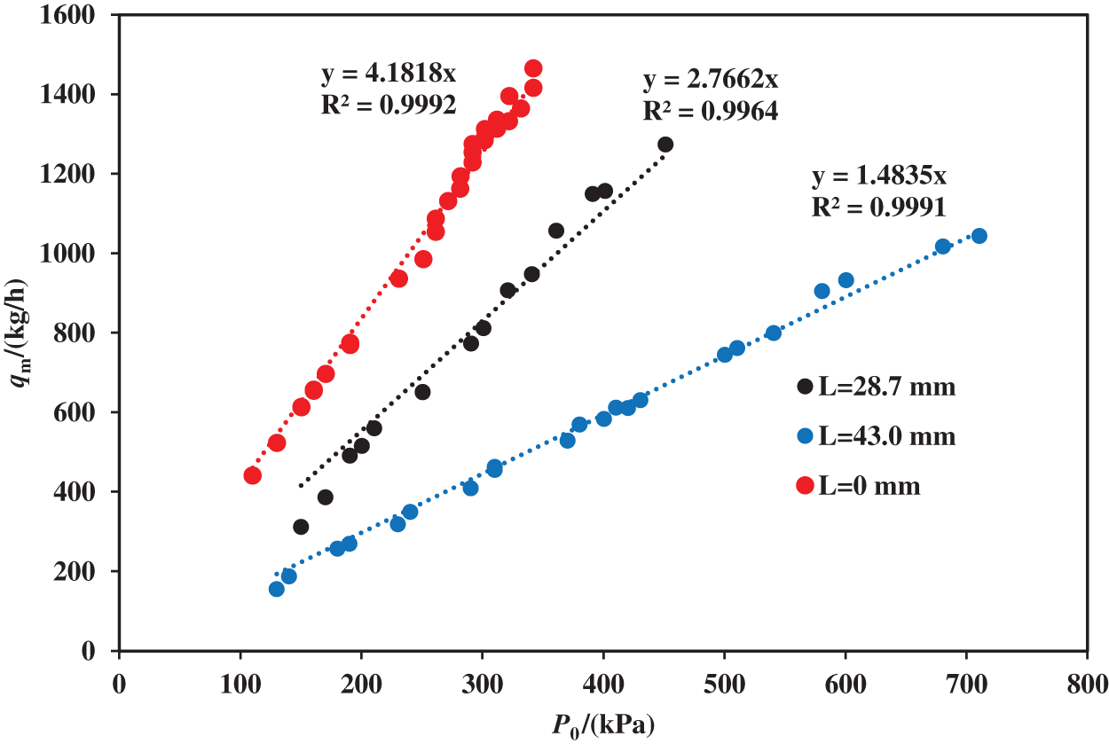
Figure 5: Relationship between critical mass flow rate and inlet stagnation pressure
It can be seen from Fig. 5 that the critical mass flow rate of the adjustable critical flow venturi nozzle has a linear relationship with the inlet stagnation pressure, and the critical mass flow rate gradually increases as the inlet stagnation pressure increases, which is similar to the properties of a standard critical flow venturi nozzle [20]. Under the same inlet stagnation pressure, the critical mass flow rate gradually decreases with the increase of the adjusting cone displacement, which proves that the adjustable critical flow venturi nozzle can achieve the adjustment of the critical mass flow rate by changing the position of the adjusting cone. The larger the displacement of the adjusting cone, the smaller the linear slope of the fitted straight line in the figure, indicating that as the displacement of the adjusting cone increases, it becomes progressively challenging to adjust the critical flow by changing the inlet pressure.
Although the inlet pressure changes, the critical mass flow is affected by both the adjusting cone displacement and the inlet pressure. However, since the steam pressure from the boiler is essentially constant during the steam injection process, the steam flow rate regulation can be achieved by the displacement of the adjusting cone.
The relative deviation of the critical flow control of the adjustable critical flow venturi nozzle can be defined as
where
Fig. 6 shows the distribution of relative deviation
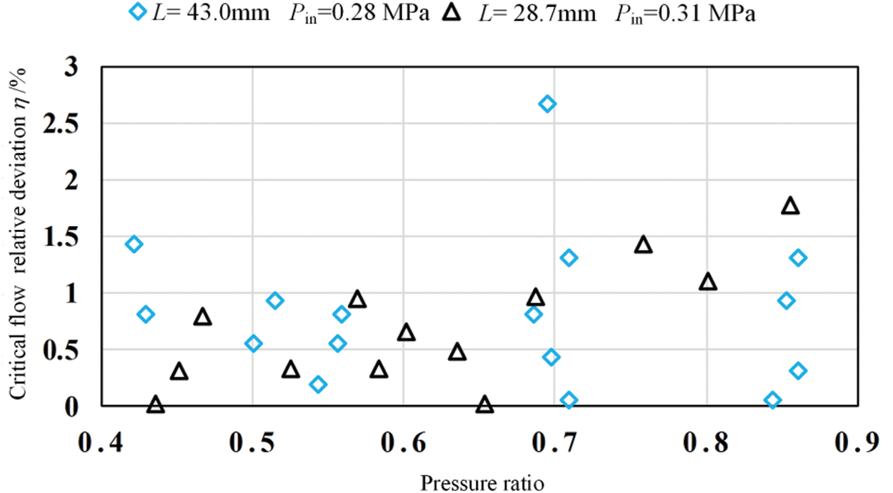
Figure 6: Distribution of the critical flow control relative deviation
Fig. 7 shows the air mass flow rate at different pressure ratios Pr(
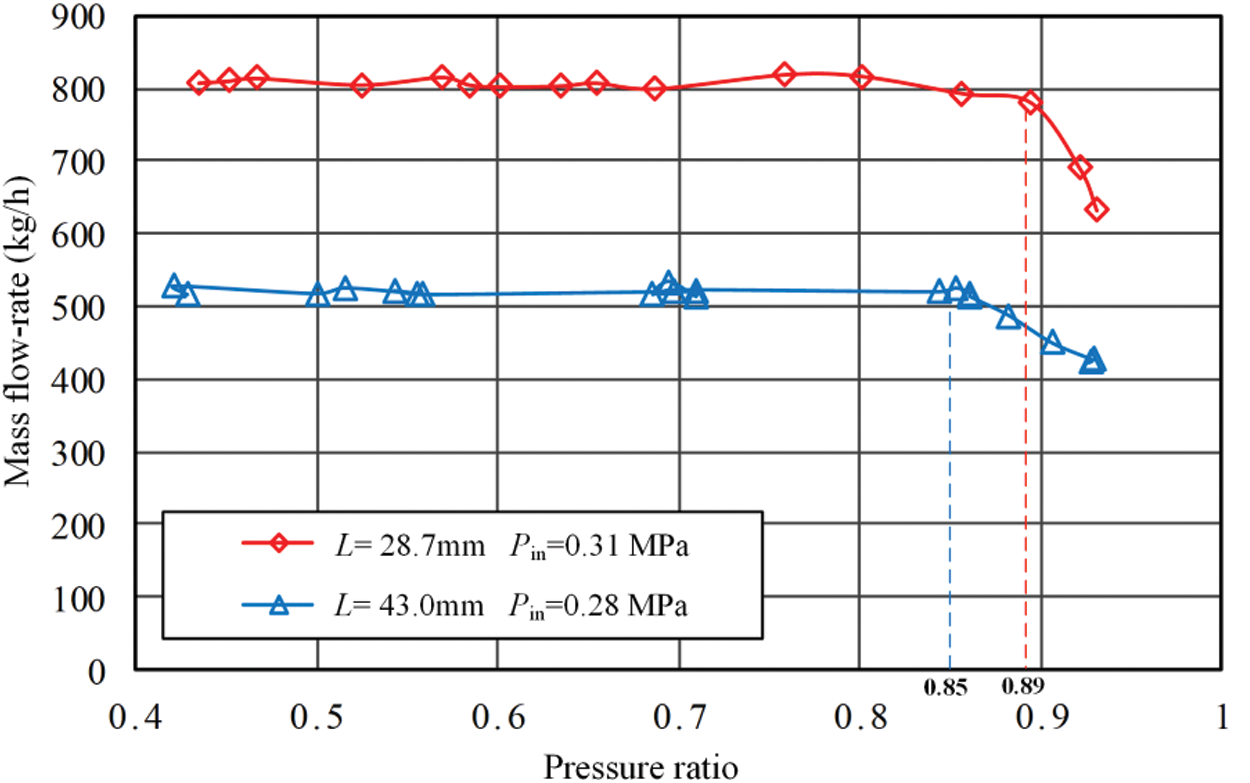
Figure 7: Critical pressure ratio of the adjustable critical flow venturi nozzle
Given that the gas is an ideal gas and the flow is one-dimensional and isentropic, the critical mass flow rate qm through the critical flow venturi nozzle can be calculated by the following equation:
where Ant is the cross-sectional area of nozzle throat; Cd is the discharge coefficient; C* is the critical flow function and it can be approximately 0.6851 for air; P0 is the absolute stagnation pressure of the air at nozzle inlet; T0 is the absolute stagnation temperature of the air at nozzle inlet; R is the universal gas constant, R = 8.314 J⋅mol−1⋅K−1; M is the molar mass of air, M = 29 g/mol; Ant, P0 and T0 can be calculated by the following equations:
where
By using the measured gas critical mass flow rate, however, as well as the inlet temperature and pressure to solve formulas (4) and (5), the discharge coefficient of the adjustable critical flow venturi nozzle under each operating condition can be calculated. Fig. 8 shows the variation of the discharge coefficient with the inlet Reynolds number. The inlet Reynolds number

Figure 8: The discharge coefficient of the adjustable critical flow venturi nozzle
where
In comparison, the discharge coefficient of the standard critical flow venturi nozzle [20] is also given in Fig. 8. It can be seen from the figure that the discharge coefficient of the adjustable critical flow venturi nozzle remains essentially constant when
The discharge coefficient of the adjustable critical flow venturi nozzle is smaller than that of the standard critical flow venturi nozzle, which may be caused by the influence of the adjusting cone on the critical flow field in the nozzle, especially on the formation of shock waves. Of course, the processing accuracy of the adjustable critical flow venturi nozzle is worse than those of the standard critical flow venturi nozzle in the experiment, which also has a particular effect on the discharge coefficient, making it smaller.
4.4 Effect of Adjusting Cone Displacement on Critical Mass Flow Rate
Fig. 9 shows the critical mass flow rates under different adjusting cone displacements and the same inlet pressure. It can be seen from the figure that at the same inlet pressure, the critical mass flow rate gradually decreases as the adjusting cone displacement increases. This verifies the flow adjustment function of the adjustable critical flow venturi nozzle. However, the larger adjusting cone displacement makes the smaller magnitude of the critical mass flow rate increase as the inlet pressure increases. This is because the smaller the throat flow area, the smaller the absolute value of the critical mass flow rate change caused by the inlet pressure change.
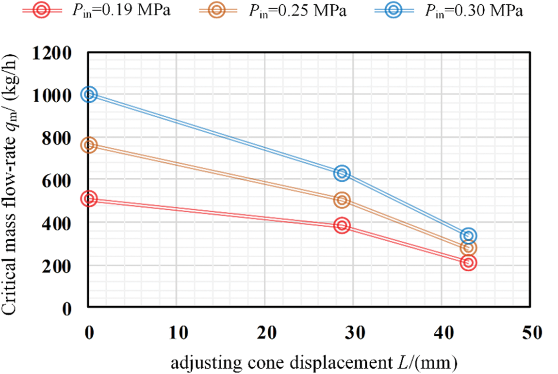
Figure 9: Critical mass flow rates under different adjusting cone displacements
4.5 Effect of Liquid on Air Critical Mass Flow Rate
Fig. 10a shows the variation of the critical mass flow rate of the adjustable critical flow venturi nozzle with the inlet pressure when the adjusting cone displacement is 28.7 mm under different liquid flow rates. As can be seen from Fig. 10a, the existence of liquid will reduce the gas critical mass flow rate at the same inlet pressure, and the liquid volume (represented by QvL in Fig. 10) becomes larger, the gas critical mass flow rate becomes smaller. This is due to the presence of liquid, which will occupy a certain flow channel area so that the actual flow area available for gas flow is reduced. And the larger the liquid volume, the more the gas flow channel is occupied, and the smaller the critical mass flow rate.
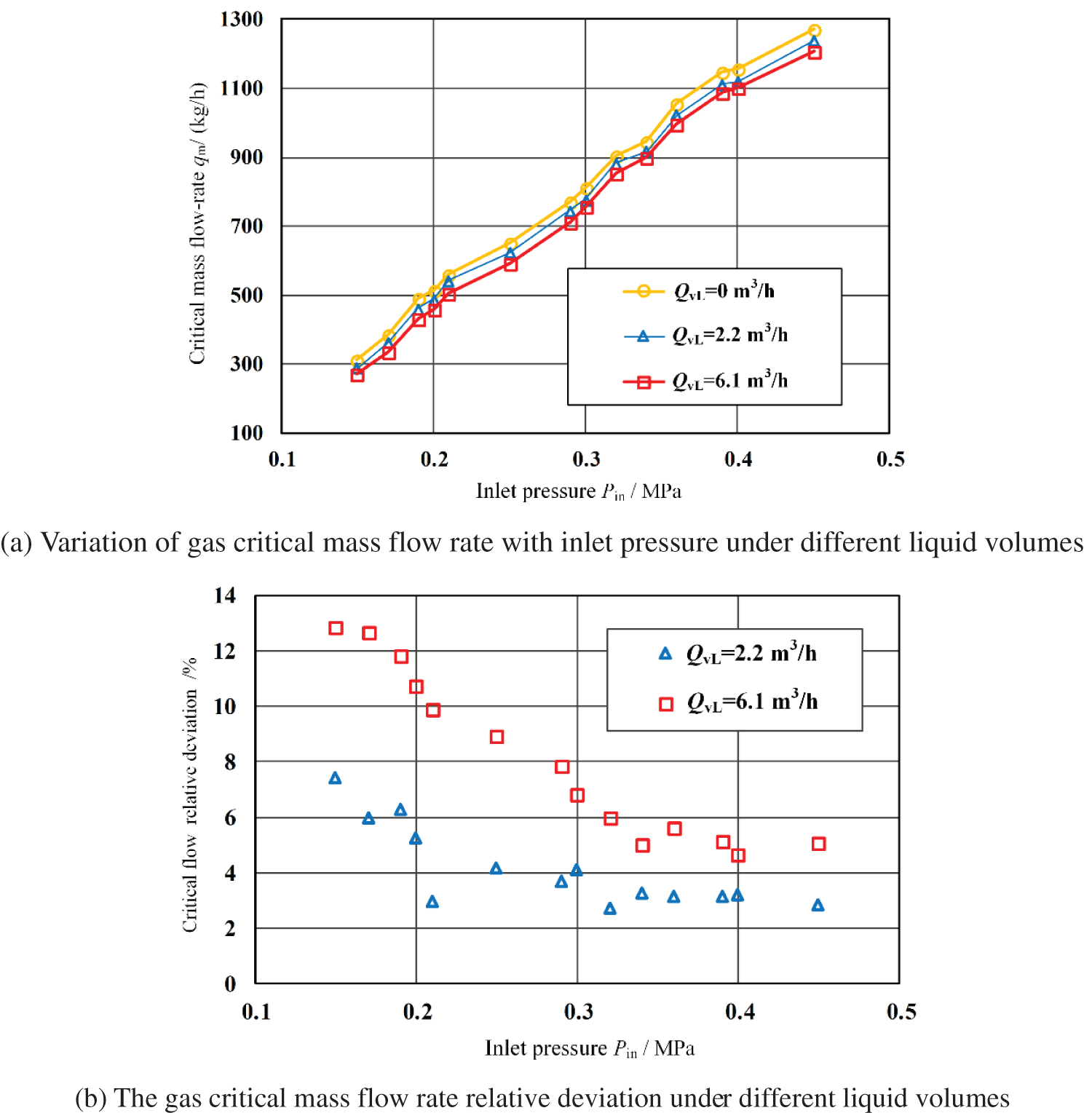
Figure 10: Effect of liquid flow rate on gas critical mass flow rate (L = 28.7 mm)
Fig. 10b shows the gas critical mass flow rate relative deviation between the gas-liquid two-phase flow and the single-phase gas flow. It can be seen from the figure that the greater the liquid volume, the greater the relative deviation of the critical mass flow rate. The lower inlet pressure leads to the more obvious effect of the liquid volume on the gas critical mass flow rate since when the liquid flow rate is the same, both the gas critical mass flow rate and the gas-liquid ratio decrease with the decrease of the inlet pressure. Therefore, the flow area occupied by the liquid amount becomes larger, and the effect on the critical mass flow rate becomes more obvious. According to Fig. 10, we can speculate that in the steam injection process, the adjustable critical flow nozzle has better critical flow rate regulation and control performance for dry or wet steam with high quality.
This paper studies the characteristics of the critical mass flow rate, the critical pressure ratio, and the discharge coefficient of the adjustable critical flow venturi nozzle through laboratory experiments, and analyzes the influences of liquid flow rate and adjusting cone displacement on the critical flow characteristics. The main conclusions include:
(1) The gas critical mass flow rate changes with the adjusting cone displacement proves that the adjustable critical flow venturi nozzle designed has a good flow adjustment function.
(2) For single-phase gas, the critical flow control deviation of the adjustable critical flow venturi nozzle is within ±3% under critical flow conditions.
(3) The discharge coefficient of the adjustable critical flow venturi nozzle is smaller than that of the standard critical flow venturi nozzle, indicating that the addition of the adjusting cone has affected the critical flow field in the nozzle.
(4) The existence of liquid flow will reduce the gas critical mass flow rate. Moreover, the larger the liquid volume, the lower the inlet pressure, and the more obvious the effect of the liquid volume on the gas critical mass flow rate.
Funding Statement: The authors would like to acknowledge the support provided by the National Natural Science Foundation of China (No. 62173049) and the open fund of the Key Laboratory of Exploration Technologies for Oil and Gas Resources (Yangtze University), Ministry of Education (Grant K2021-17).
Conflicts of Interest: The authors declare that they have no conflicts of interest to report regarding the present study.
References
1. Sun, F., Yao, Y., Chen, M., Li, X., Zhao, L. et al. (2017). Performance analysis of superheated steam injection for heavy oil recovery and modeling of wellbore heat efficiency. Energy, 125, 795–804. DOI 10.1016/j.energy.2017.02.114. [Google Scholar] [CrossRef]
2. Liu, M., Niu, P., Zhang, X., Zheng, W., Wang, Z. et al. (2022). Equal quality distribution of two-phase fluid by isokinetic principle. SPE Production & Operations, 37(3), 475–492. DOI 10.2118/209793-PA. [Google Scholar] [CrossRef]
3. Zhang, B., Zhang, X., Wang, D., Huang, S. (2013). Equal quality distribution of gas–liquid two-phase flow by partial separation method. International Journal of Multiphase Flow, 57, 66–77. DOI 10.1016/j.ijmultiphaseflow.2013.07.006. [Google Scholar] [CrossRef]
4. Liang, F., Zheng, H., Sun, Y., Song, L. (2016). Experimental investigation of phase split of gas–liquid two-phase flow through small holes at the pipe wall. Experimental Thermal and Fluid Science, 76, 330–341. DOI 10.1016/j.expthermflusci.2016.03.029. [Google Scholar] [CrossRef]
5. Chien, S. F., Rubel, M. T. (1992). Phase splitting of wet steam in annular flow through a horizontal impacting tee. SPE Production Engineering, 7(4), 368–374. DOI 10.2118/22764-PA. [Google Scholar] [CrossRef]
6. Wren, E., Azzopardi, B. J. (2004). Affecting the phase split at a large diameter T-junction by using baffles. Experimental Thermal and Fluid Science, 28(8), 835–841. DOI 10.1016/j.expthermflusci.2003.12.017. [Google Scholar] [CrossRef]
7. dos Reis, E., Goldstein Jr, L. (2013). Fluid dynamics of horizontal air–water slug flows through a dividing T-junction. International Journal of Multiphase Flow, 50, 58–70. DOI 10.1016/j.ijmultiphaseflow.2012.10.008. [Google Scholar] [CrossRef]
8. Zhang, X., Wang, D., Liao, R., Zhao, H., Shi, B. (2019). Study of mechanical choked venturi nozzles used for liquid flow controlling. Flow Measurement and Instrumentation, 65, 158–165. DOI 10.1016/j.flowmeasinst.2018.12.001. [Google Scholar] [CrossRef]
9. Cengel, Y. A., Boles, M. A., Kanoğlu, M. (2011). Thermodynamics: An engineering approach, vol. 5. USA: McGraw-Hill. [Google Scholar]
10. White, F. (2003). Fluid mechanics, 5th edition, pp. 599–632. USA: McGraw-Hill. [Google Scholar]
11. Hu, Q., Yan, X., Huang, S., Yu, J. (2018). A critical heat flux model for saturated flow boiling on the downward curved heated surface. Annals of Nuclear Energy, 114, 458–463. DOI 10.1016/j.anucene.2017.12.038. [Google Scholar] [CrossRef]
12. Lee, C. H., Mudawwar, I. (1988). A mechanistic critical heat flux model for subcooled flow boiling based on local bulk flow conditions. International Journal of Multiphase Flow, 14(6), 711–728. DOI 10.1016/0301-9322(88)90070-5. [Google Scholar] [CrossRef]
13. Li, C., Cao, P., Zhang, H., Cui, L. (2018). Throat diameter influence on the flow characteristics of a critical venturi sonic nozzle. Flow Measurement and Instrumentation, 60, 105–109. DOI 10.1016/j.flowmeasinst.2018.02.012. [Google Scholar] [CrossRef]
14. Yoon, W., Yoon, H., Ahn, J., Ahn, K. (2021). Flow measurement and instrumentation flow control characteristics of throttling venturi valve with adjustable area. Flow Measurement and Instrumentation, 81, 102034. DOI 10.1016/j.flowmeasinst.2021.102034. [Google Scholar] [CrossRef]
15. Hong, K. C., Griston, S. (1997). Best practice for the distribution and metering of two-phase steam. SPE Production & Facilities, 12(3), 173–180. DOI 10.2118/35422-PA. [Google Scholar] [CrossRef]
16. Kim, J. H., Kim, H. D., Park, K. A. (2006). Computational/experimental study of a variable critical nozzle flow. Flow Measurement and Instrumentation, 17(2), 81–86. DOI 10.1016/j.flowmeasinst.2005.11.002. [Google Scholar] [CrossRef]
17. Yanagihara, S., Mochizuki, O., Sato, K., Saito, K. (1999). Variable area venturi-type exhaust gas flow meter. JSAE Review, 20(2), 265–267. DOI 10.1016/S0389-4304(99)00003-X. [Google Scholar] [CrossRef]
18. Yanagihara, S., Mochizuki, O. (1996). Cvs system with variable area cfv. JSAE, 50(3), 7–12. [Google Scholar]
19. Zhang, X., Wang, D., Guo, S., Liu, M., Lu, G. et al. (2015). China Patent CN104535121A. China: Xi’an. [Google Scholar]
20. ISO (2005). Measurement of gas flow by means of critical flow venturi nozzles ISO/CD. [Google Scholar]
21. Hillbrath, H. S., Dill, W. P., Wacker, W. A. (1975). The choking pressure ratio of a critical flow venturi. Journal of Engineering for Industry, 97(4), 1251–1256. DOI 10.1115/1.3438737. [Google Scholar] [CrossRef]
22. Wang, C., Ding, H., Zhao, Y. (2014). Influence of wall roughness on discharge coefficient of sonic nozzles. Flow Measurement and Instrumentation, 35, 55–62. DOI 10.1016/j.flowmeasinst.2013.11.007. [Google Scholar] [CrossRef]
23. Mikheev, N., Saushin, I., Kratirov, D. (2019). Critical flow venturi with a step-wall diffuser. Flow Measurement and Instrumentation, 68, 101589. DOI 10.1016/j.flowmeasinst.2019.101589. [Google Scholar] [CrossRef]
24. Takegawa, N., Ishibashi, M., Morioka, T. (2020). Experimental study on improving the critical back-pressure ratio using a step in a critical-flow venturi nozzle. Flow Measurement and Instrumentation, 71, 101682. DOI 10.1016/j.flowmeasinst.2019.101682. [Google Scholar] [CrossRef]
Cite This Article
 Copyright © 2023 The Author(s). Published by Tech Science Press.
This work is licensed under a Creative Commons Attribution 4.0 International License , which permits unrestricted use, distribution, and reproduction in any medium, provided the original work is properly cited.
 Downloads
 Citation Tools