
 Submit a Paper
 Propose a Special lssue
 Open Access
ARTICLE
Analysis of the Performances of a New Type of Alumina Nanocomposite Structural Material Designed for the Thermal Insulation of High-Rise Buildings
Eastern Liaoning University, Faculty of Urban Construction, Dandong, 118001, China
* Corresponding Author: Yue Yu. Email:
(This article belongs to the Special Issue: Advanced Materials, Processing and Testing Technology)
Fluid Dynamics & Materials Processing 2023, 19(3), 697-709. https://doi.org/10.32604/fdmp.2022.021482
Received 17 January 2022; Accepted 16 May 2022; Issue published 29 September 2022
 View Full Text
 Download PDF
Abstract
The sol-gel method is used to prepare a new nano-alumina aerogel structure and the thermal properties of this nanomaterial are investigated comprehensively using electron microscope scanning, thermal analysis, X-ray and infrared spectrometer analysis methods. It is found that the composite aerogel alumina material has a multi-level porous nano-network structure. When employed for the thermal insulation of high-rise buildings, the alumina nanocomposite aerogel material can lead to effective energy savings in winter. However, it has almost no energy-saving effect on buildings where energy is consumed for cooling in summer.Keywords
Thermal insulation materials are widely used in the field of building energy conservation. Architects use thermal insulation materials to reduce the heat transfer of the building envelope, and this is an essential means to reduce building energy consumption [1]. The functional model of commonly used thermal insulation materials reduces heat transfer and heat flow by reducing heat conduction, heat radiation, and heat convection. Materials generally have loose and porous microstructures or closed vacuum layers that hinder air convection or low-emissivity materials. Alternatively, the materials can also be combined to form a composite thermal insulation enclosure structure. For example, various foam sandwich panels, composite walls with lightweight insulation layers, low-radiation insulating glass, etc.
Aerogel is a new type of lightweight nanoporous material. It consists of many nano-scale microporous structures smaller than the mean free path of air molecules. The nanopores prevent the air molecules in it from moving freely so that the aerogel has an ultra-low thermal conductivity that is better than that of a static air layer [2]. The melting point of alumina is higher than 2000°C. The aerogel prepared by us has the good thermal insulation effect of aerogel and the good high-temperature thermal stability of alumina. Preparing pure alumina aerogel can be divided into the inorganic aluminum salt method and the organometallic aluminum alkoxide method. The precursors used in the inorganic aluminum salt method are mainly
Then Researcher add peptizer to promote polycondensation and prepare the alumina gel. Some scholars use acetic acid as a peptizer. They used a two-step method to supercritically dry methanol at 60°C to obtain a massive aerogel density of 37 kg/m3 and a thermal conductivity of 0.029 W/m⋅K at room temperature. Some scholars used this method to prepare bulk alumina aerogel at 60°C using ethyl acetoacetate as a chelating agent. The research mentioned above on alumina aerogel mainly increases its specific surface area. This article adopts the polymerization method with aluminum sec-butoxide as the precursor and nitric acid as the catalyst. Researcher prepare alumina aerogel at room temperature and study its thermal properties.
This article use aluminum sec-butoxide as the precursor. At the same time, This article uses 68% concentrated nitric acid as a catalyst. A step-by-step controlled hydrolysis and polycondensation process is used to prepare wet alumina gel. First, pour an appropriate amount of absolute ethanol and nitric acid into the reaction vessel at room temperature before mixing and stirring evenly. Then add aluminum sec-butoxide dropwise and continue stirring until the sol is clear and transparent. Pour the evenly mixed ethanol aqueous solution into the reaction vessel and continue stirring. Let it stand to form a wet alumina gel when ready to gel. Researcher had the wet alumina gel for several days. Finally, supercritical alcohol drying is carried out in the high-pressure preparation [4]. Researcher sell a certain amount of alcohol and wet alumina gel in the autoclave. Researcher increase the temperature at a rate of 2 °C/min until the temperature and pressure in the kettle reach the supercritical point of alcohol. Then lower the temperature and release the pressure until the temperature in the strip drops to room temperature to take out the alumina aerogel. Researcher will label it as A.
2.2 Characterization of Samples
This article uses a Philips XL-30 field emission scanning electron microscope (SEM) to observe the microscopic morphology of the sample. Accurately measure the mass and volume of the sample to calculate the density of the sample. This article uses the Hot Disk thermal analyzer to test the sample’s thermal conductivity. This article uses a pore size distribution meter to analyze the pore structure of the sample. DX-2700 X-ray diffractometer was used to analyze the crystalline structure of the sample and a Fourier transform infrared spectrometer to test the infrared absorption characteristics of the sample. At the same time, Researcher analyzed the internal groups and components of the sample.
2.3 Temperature Influence of High-Rise Building Structure
Due to the large differences in climate conditions in different regions, the temperature values of high-rise buildings in China also have huge differences. The temperature difference between indoor and outdoor conditions in high-rise buildings in the north is far greater than in summer. Therefore, the structural temperature of high-rise buildings can be selected as the lowest temperature value with weaker sunshine conditions. In the southern region, due to abundant sunshine, the temperature difference between indoor and outdoor conditions in high-rise buildings is relatively small [5]. Therefore, the structural temperature of high-rise buildings can be selected as the lowest temperature value with strong sunshine conditions in summer. This article use Eq. (1) to calculate,
The value of
2.4 Establishing the Limits of the Heat Transfer Model
The limit of the heat transfer model is the actual solution condition of the heat transfer model of the high-rise building structure. This can be divided into initial conditions and boundary conditions. The external environment of high-rise buildings is relatively evenly distributed around 6 a.m., so the temperature at this time can be used as the initial condition of the heat transfer model [8]. The boundary conditions refer to the heat exchange conditions between the surface of the high-rise building structure and the surrounding environment. The boundary conditions of different boundaries of high-rise buildings are not the same, so they need to be treated differently. Since most of the interior rooms of high-rise buildings are equipped with constant temperature air conditioners, the first category of boundary conditions can be used. The temperature T on the surface of the high-rise building structure is a function of time
The surface of the high-rise building structure is in contact with the external environment, and the surface temperature is closely related to the air temperature. The surface temperature of high-rise buildings is affected by sunlight. This article utilizes Eqs. (5) and (6), and uses Eq. (7) to obtain the limits of the heat transfer model.
2.5 The Analysis Process of the Effect of the Temperature Field on the Building Structure
I This article discretizes the use of the heat transfer model limits of the heat transfer model of the high-rise building structure. At this point, this article has a closed set of mathematical equations.
II The solution this article obtained by operating the mathematical equations is the temperature value of discrete points on the high-rise building structure.
The discretization process mainly considers the role of high-rise building structure surface and thermal insulation materials. Before solving the model, it is necessary to discretize the model first. This article set the thickness of the high-rise building as H, and there is a total of n units. Set the horizontal direction as the x axis. The physical quantity of each unit in the
Suppose the heat flow vector of the high-rise building structure is
If the heat transfer inside the high-rise building is ignored, the heat transferred to the unit is the increment of the unit in unit time:
If the thermal conductivity is
According to Eq. (11), the temperature value of each point in the high-rise building structure can be calculated.
3.1 Composition of Alumina Aerogel Sample
As seen in Fig. 1, the alumina aerogels obtained by this process are mostly pseudo-boehmite phase or polycrystalline boehmite phase. The different peaks in Fig. 1 correspond to the different crystal faces of the boehmite crystal phase. Among them, the diffraction peak
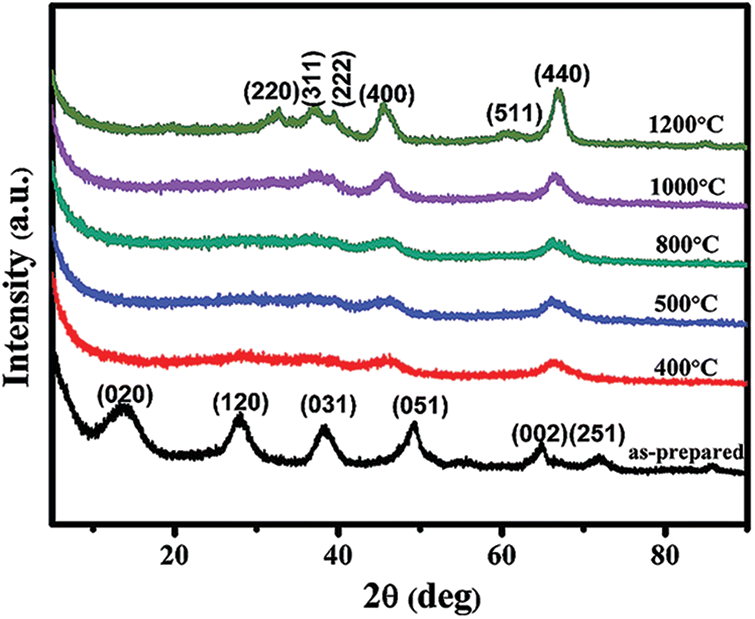
Figure 1: XRD pattern of alumina aerogel
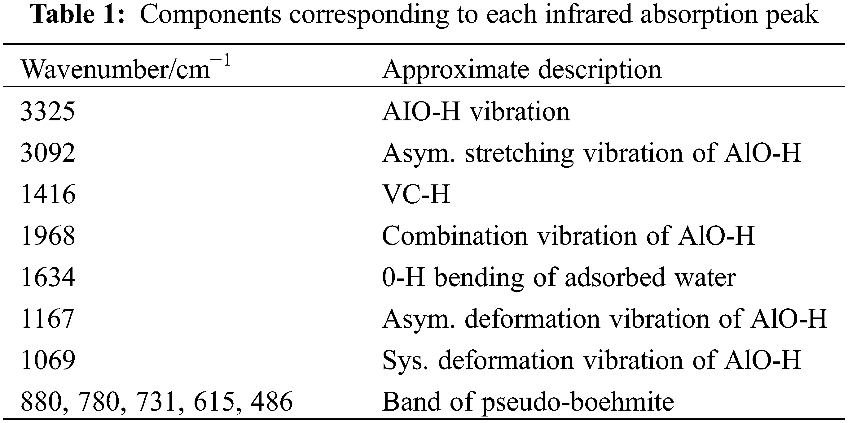
Fig. 2 shows the infrared spectrum of alumina aerogel. Table 1 lists the group vibration modes corresponding to each peak. The absorption peak near 1634 cm−1 represents the bending vibration of H-O-H. This indicates that the sample contains water. The peak at 1416 cm−1 corresponds to the vibration of the C-H bond, and the peak is smaller. This indicates a small number of organic groups in the sample. The peaks at 3325, 3092, 1968, 1167, and 1069 cm−1 respectively represent AlO-H vibration, AlO-H anti-stretching symmetrical vibration, AlO-H combined vibration, AlO-H anti-symmetric deformation vibration, and AlO-H symmetric deformation vibration. All vibration modes of AlO-H correspond to polycrystalline boehmite. 880, 780, 731, 615, 486 cm−1 are pseudo-Boehm peaks and correspond to boehmites. It can be seen from the infrared spectrum that the aerogel has more boehmite components and has sharper peaks. This is consistent with the results of the XRD pattern.

Figure 2: The infrared spectrum of the sample
3.2 The Influence of Preparation Parameters on Alumina Gel
As the sol’s reaction temperature increases, the gel’s homogeneity, and transparency increase, but the gel skeleton structure weakens (Fig. 3). If the reaction temperature is too low, the gel structure is not uniform. The reaction temperature is too high, and the sol does not gel. As the concentration of nitric acid increases, the gel time increases rapidly. If nitric acid is added too little, the sol will agglomerate [10].
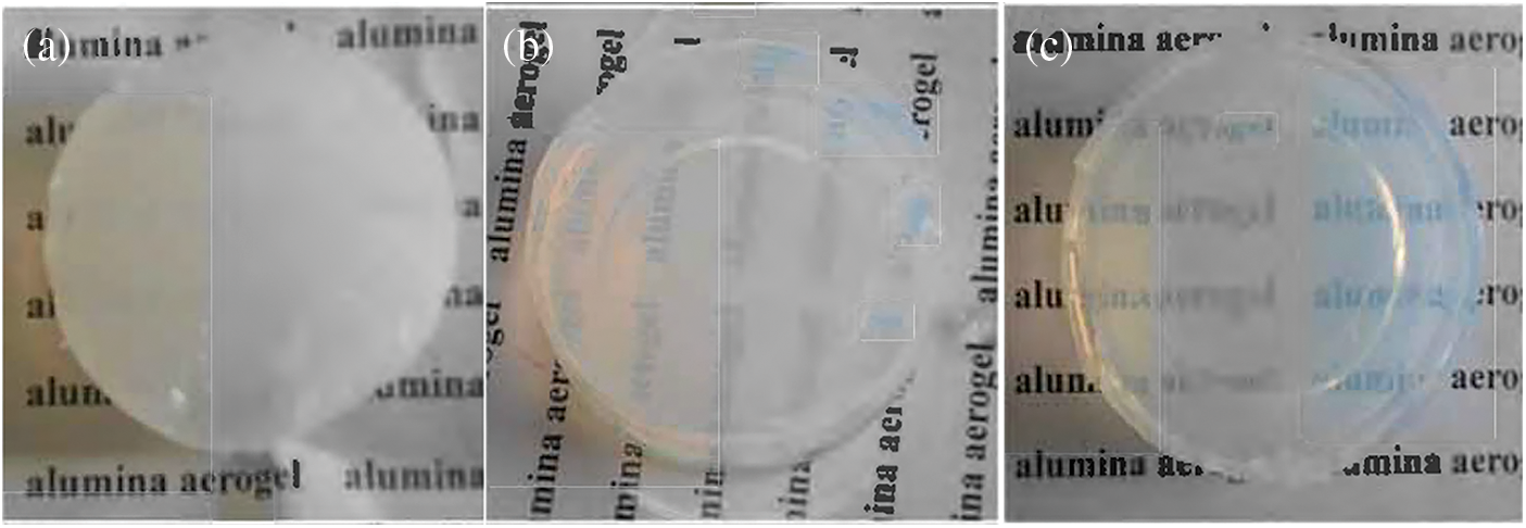
Figure 3: The effect of temperature on the gel; (a) 20°C, (b) 40°C, (c) 60°C
On the contrary, sol does not gel. The amount of water in the hydrolysis and polycondensation reaction of the sol also affects the speed of the gel and the structure of the gel. Fig. 4 shows that as the amount of water added increases, the gel time shows an upward trend.

Figure 4: The effect of the amount of water on the gel time
3.3 Nanoporous Structure of Alumina Aerogel
The alumina aerogel block is milky white, bluish, and has no apparent cracks. It becomes light blue translucent after heat treatment at 1200°C. The unique structural parameters such as the three-dimensional nanoparticle skeleton and high porosity of aerogel determine its heat resistance and heat resistance properties, and structural strength [11]. Fig. 5 is a scanning electron micrograph of the obtained alumina aerogel. The aerogel in this experiment has a typical colloidal structure with pores and spherical particles.

Figure 5: SEM image of the sample
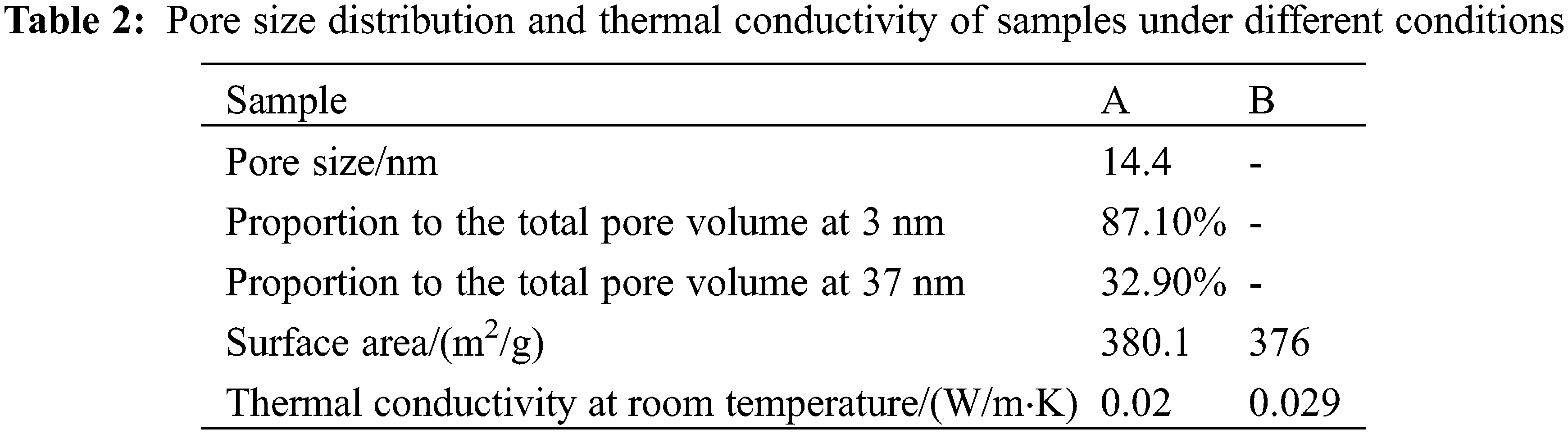
Fig. 6 shows the pore size distribution of aerogels. There are two obvious peak pore diameters in this experiment’s aerogel pore size distribution, and the peak pore size differs by the orders of magnitude. The smaller peak apertures are mainly distributed around 3 nm, with sharp and high [12]. The larger peak pore size is mainly concentrated around 37 nm, the pore size distribution is vast, and the peak value is low. The specific surface area is shown in Table 2. The quantity is 380 m2/g.

Figure 6: Pore size distribution diagram of the sample
3.4 Thermal Properties of Alumina Aerogel
Table 2 lists the thermal conductivity values of alumina aerogel at room temperature. The alumina aerogel prepared in this paper has good heat insulation performance, and the thermal conductivity at room temperature is only 0.020 W/m⋅K. The thermal conductivity of aerogel is mainly composed of three parts: solid heat conduction, gaseous heat conduction, and radiant heat conduction. Solid heat conduction is the heat conduction of solid particles that make up its network structure. Gaseous heat conduction refers to the heat conduction of gas molecules in nanopores. It consists of convection heat transfer and heat conduction of the gas itself [13]. The size of the pores in the aerogel skeleton is only tens of nanometers. This dramatically limits the thermal movement of gas molecules. Our convective heat conduction can be ignored, and the gaseous heat conduction is only the gas heat dissipation transfer contribution.
It can be seen from Fig. 6 that the pore diameters of alumina aerogels are all within 70 nm. It is smaller than the mean free path of the main molecules in the air, and it is difficult for the molecules in the pores to collide. Therefore, the contribution to gaseous heat conduction is small [14]. In addition, the size of the two peak apertures in the pore size distribution diagram differs by several orders of magnitude. This shows that the alumina aerogel prepared by this process has formed a secondary porous nano-skeleton structure similar to silica aerogel (Fig. 7). In Table 2, the primary pores accounted for 87.1% of the total pore volume, and the secondary structure accounted for 32.9% of the total pore volume. This means that the pores of the primary structure are particularly dense, and the pore structure is more difficult to cause gas flow. And the pore size of 3 nm is an order of magnitude smaller than the mean free path of gas molecules. The collision between gas molecules is more difficult to transfer heat, which significantly reduces the gaseous heat transfer [15]. Compared with the single-structure alumina aerogels obtained by other processes, it is found that the aerogels prepared by this process have obvious secondary pore structure, which dramatically increases the gas-solid interface. This also increases the collision probability between gas molecules and the interface. A large amount of energy is dissipated at the interface and is not conducive to solid-state heat conduction. As a result, the overall thermal conductivity is greatly reduced.

Figure 7: Schematic diagram of the hierarchical structure of silica aerogel
The diffraction peaks corresponding to boehmite crystals are particularly strong in the XRD pattern of the sample, which means that the crystallinity of the sample is high. The high crystallinity of the aerogel is mainly due to the high crystallinity of the first-stage particles. More first-order crystal particles can increase the number of collisions with crystal faces [16]. Most of the energy is dissipated at the crystal plane during internal transfer, which greatly reduces the heat conduction.
3.5 Hotbox Test Window Test Piece and Comparison Hot Box Test System
This article uses two identical hot boxes in the same outdoor environment for thermal performance comparison. The dimensions of the two hot boxes are both 750 mm × 500 mm × 900 mm. Install openings for the test enclosure structure measuring 250 mm × 650 mm on the same side elevation. There are vents with dimensions of 50 mm × 50 mm at the same position on the opposite wall. The geometric dimensions are the same. In addition, the material and structure of the enclosure structure on each side of the two hot boxes are the same. The outer layer is wrapped with a 2 mm thick epoxy resin board with good weather resistance and high hardness [17]. The inner layer is a 100 mm thick extruded foam insulation board for heat insulation. The bottom surface is a 100 mm thick extruded foam insulation board. It is placed on a 50 mm thick extruded foam insulation board cushion and then placed on the roof platform. The junctions of the hot box walls are airtightly connected by waterproof tape. The outer side of the tape is reinforced and fixed by an epoxy resin board connecting the two wall surfaces with angle steel.
The test window specimens are divided into target specimens and comparison specimens. The target test piece is constructed as two sheets of 4 mm thick transparent glass sandwiched between a 4 mm thick alumina aerogel translucent material layer. The structure of the comparative test piece was a translucent film attached to ordinary 4 m thick flat glass [18]. This ensures that the light transmittance of the contrast specimen is equal to the target specimen. At the same time, this can reduce the difference in the thermal environment inside the hot box caused by the difference in transmitted light. The test results show that the light transmittance of the comparison test piece after the film treatment is similar to the target test piece. The data is between 10% and 15%. This article installed the two test pieces on the windows of the two hotboxes respectively during the experiment. The thermal performance difference between the two test pieces was compared by measuring the thermal environment parameters inside the hot box. The entire comparative hot box experimental test system is shown in Fig. 8. The temperature measurement uses a platinum resistance Pt100 temperature sensor. Heat flow measurement uses a heat flow sheet. A multi-channel data logger is used for data recording. Record temperature and heat flow data every 1 min. The experimental system uses seven platinum resistance temperature sensors and two hot strips. The platinum resistance temperature sensor measures the internal air temperature of the two hot boxes, and the temperature of the center of the inner glass wall and the outer wall, respectively [19]. Another temperature sensor measures the outdoor air temperature.
Figure 8: Comparison of the hot box test system and schematic diagram of each test point
The hot target box was installed with alumina aerogel fine composite panel specimens in the comparative hot box experiment. Install the test piece of an ordinary glass film compared to the hot box. Turn on the data logger to record temperature and heat flow data. Some of the experimental data obtained are as follows [20]. Fig. 9 shows the comparison of the internal air temperature between the target hot box and the comparison hot box. From 19:00 to 06:00 of the next day, the temperature curves of the two overlapped, and the overall temperature remained under a slow cooling trend. During 06:00–09:40, the heat flow data shows the heat inside the hot box. The air temperature inside the hot target box is slightly slower than that of the comparison hot box, but the difference is not much. This indicates that the thermal insulation effect of the alumina aerogel translucent composite board during this period is slightly better than that of ordinary glass, but the effect is not obvious. The heat flow data during the period of 09:40–14:00 indicates that the heat inside the hotbox loses heat. The internal air temperature of the hot target box is slightly higher than the internal air temperature of the contrast hot box. This shows that the alumina aerogel laminated glass with a better heat preservation effect hinders the heat dissipation inside the hot box. Therefore, the internal air temperature of the hot target box is relatively high during this period [21]. Combining multiple sets of data, it is concluded that the air temperature difference between the target hot box and the comparison hot box varies within the range of −2.3°C to 2.4°C. The average value of the absolute value of the difference is only 0.27°C.

Figure 9: The comparison between the target hot box installed with aluminum oxide aerogel translucent composite board and the ordinary glass with film, the internal air temperature fluctuation of the hot box
In summer, the curtain wall enclosure structure is not better the heat preservation, the more energy-saving. Because the alumina aerogel layer with good thermal insulation performance may hinder indoor heat dissipation in summer, increasing the cooling load is not conducive to energy saving. At the same time, it can be concluded that the aluminum oxide aerogel translucent composite insulation board has no energy-saving advantage compared to the filmed ordinary glass with the same transmittance in the summer climate environment. This result directly proves the conclusion drawn during the energy consumption simulation. In summer, the alumina aerogel translucent composite insulation board has no obvious energy-saving gain in the climate zone, where refrigeration energy consumption is the mainstay.
This article uses aluminum sec-butoxide as the precursor and nitric acid as the catalyst. In the experiment, an alumina aerogel with thermal conductivity of 0.020 W/m⋅K and a density of 120 kg/m3 can be prepared at room temperature. The secondary pore crystal structure formed by this kind of gas glue increases the number of collisions between energy and crystal faces and interfaces. Most of the energy is dissipated at the crystal and interface. This article believes that the experimentally prepared composite aerogel alumina material has a multi-layered porous nano-network structure. In the high-rise building information thermal insulation experiment, the alumina nanocomposite structure material aerogel translucent composite thermal insulation board has important energy-saving significance for buildings with heating energy consumption in winter and has great promotion value.
Funding Statement: This work is financially supported by a University-level doctoral research start-up fund in 2019.
Conflicts of Interest: The author declares that they have no conflicts of interest to report regarding the present study.
References
1. Derazkola, H. A., Khodabakhshi, F. (2020). A novel fed friction-stir (FFS) technology for nanocomposite joining. Science and Technology of Welding and Joining, 25(2), 89–100. DOI 10.1080/13621718.2019.1631534. [Google Scholar] [CrossRef]
2. Wagih, A., Abu-Oqail, A., Fathy, A. (2019). Effect of GNPs content on thermal and mechanical properties of a novel hybrid Cu-Al2O3/GNPs coated Ag nanocomposite. Ceramics International, 45(1), 1115–1124. DOI 10.1016/j.ceramint.2018.10.001. [Google Scholar] [CrossRef]
3. Sharma, A., Sharma, V. M., Paul, J. (2020). Fabrication of bulk aluminum-graphene nanocomposite through friction stir alloying. Journal of Composite Materials, 54(1), 45–60. DOI 10.1177/0021998319859427. [Google Scholar] [CrossRef]
4. Taherzadeh Mousavian, R., Behnamfard, S., Heidarzadeh, A., Taherkhani, K., Azari Khosroshahi, R. et al. (2021). Incorporation of SiC ceramic nanoparticles into the aluminum matrix by a novel method: Production of a metal matrix composite. Metals and Materials International, 27(8), 2968–2976. DOI 10.1007/s12540-019-00604-9. [Google Scholar] [CrossRef]
5. Rahimi, S., SharifianJazi, F., Esmaeilkhanian, A., Moradi, M., Samghabadi, A. H. S. (2020). Effect of SiO2 content on Y-TZP/Al2O3 ceramic-nanocomposite properties as potential dental applications. Ceramics International, 46(8), 10910–10916. DOI 10.1016/j.ceramint.2020.01.105. [Google Scholar] [CrossRef]
6. Abd-Elwahed, M. S., Meselhy, A. F. (2020). Experimental investigation on the mechanical, structural and thermal properties of Cu–ZrO2 nanocomposites hybridized by graphene nanoplatelets. Ceramics International, 46(7), 9198–9206. DOI 10.1016/j.ceramint.2019.12.172. [Google Scholar] [CrossRef]
7. Sadoun, A. M., Mohammed, M. M., Fathy, A., El-Kady, O. A. (2020). Effect of Al2O3 addition on hardness and wear behavior of Cu–Al2O3 electro-less coated Ag nanocomposite. Journal of Materials Research and Technology, 9(3), 5024–5033. DOI 10.1016/j.jmrt.2020.03.020. [Google Scholar] [CrossRef]
8. Yang, L., Chen, Y., Wang, M., Shi, S., Jing, J. (2020). Fused deposition modeling 3D printing of novel poly (vinyl alcohol)/graphene nanocomposite with enhanced mechanical and electromagnetic interference shielding properties. Industrial & Engineering Chemistry Research, 59(16), 8066–8077. DOI 10.1021/acs.iecr.0c00074. [Google Scholar] [CrossRef]
9. Hamed, M. M., El-Din, A. S., Abdel-Galil, E. A. (2019). Nanocomposite of polyaniline functionalized Tafla: Synthesis, characterization, and application as a novel sorbent for selective removal of Fe(III). Journal of Radioanalytical and Nuclear Chemistry, 322(2), 663–676. DOI 10.1007/s10967-019-06733-0. [Google Scholar] [CrossRef]
10. Sadoun, A. M., Fathy, A., Abu-Oqail, A., Elmetwaly, H. T., Wagih, A. (2020). Structural, mechanical and tribological properties of Cu–ZrO2/GNPs hybrid nanocomposites. Ceramics International, 46(6), 7586–7594. DOI 10.1016/j.ceramint.2019.11.258. [Google Scholar] [CrossRef]
11. Gangwar, S., Arya, P., Pathak, V. K. (2021). Optimal material selection for ship body based on fabricated zirconium dioxide/silicon carbide filled aluminium hybrid metal alloy composites using novel fuzzy based preference selection index. Silicon, 13(8), 2545–2562. DOI 10.1007/s12633-020-00600-4. [Google Scholar] [CrossRef]
12. Zhang, M., Jin, W., Yang, F., Duke, M., Dong, Y. et al. (2020). Engineering a nanocomposite interlayer for a novel ceramic-based forward osmosis membrane with enhanced performance. Environmental Science & Technology, 54(12), 7715–7724. DOI 10.1021/acs.est.0c02809. [Google Scholar] [CrossRef]
13. Khdair, A. I., Fathy, A. (2020). Enhanced strength and ductility of Al-SiC nanocomposites synthesized by accumulative roll bonding. Journal of Materials Research and Technology, 9(1), 478–489. DOI 10.1016/j.jmrt.2019.10.077. [Google Scholar] [CrossRef]
14. Ostovan, F., Amanollah, S., Toozandehjani, M., Shafiei, E. (2020). Fabrication of Al5083 surface hybrid nanocomposite reinforced by CNTs and Al2O3 nanoparticles using friction stir processing. Journal of Composite Materials, 54(8), 1107–1117. DOI 10.1177/0021998319874849. [Google Scholar] [CrossRef]
15. Mehrizi, M. Z., Momeni, M. R., Beygi, R., Kim, B. H., Kim, S. K. (2019). Reaction pathway of NiAl/WC nanocomposite synthesized from mechanical activated Ni-Al-W-C powder system. Ceramics International, 45(9), 11833–11837. DOI 10.1016/j.ceramint.2019.03.062. [Google Scholar] [CrossRef]
16. Gudipudi, S., Nagamuthu, S., Subbian, K. S., Chilakalapalli, S. P. R. (2020). Enhanced mechanical properties of AA6061-B4C composites developed by a novel ultra-sonic assisted stir casting. Engineering Science and Technology, an International Journal, 23(5), 1233–1243. DOI 10.1016/j.jestch.2020.01.010. [Google Scholar] [CrossRef]
17. Narimani, M., Teimouri, A., Shahbazarab, Z. (2019). Synthesis, characterization and biocompatible properties of novel silk fibroin/graphene oxide nanocomposite scaffolds for bone tissue engineering application. Polymer Bulletin, 76(2), 725–745. DOI 10.1007/s00289-018-2390-2. [Google Scholar] [CrossRef]
18. Hynes, N. R. J., Sankaranarayanan, R., Tharmaraj, R., Pruncu, C. I., Dispinar, D. (2019). A comparative study of the mechanical and tribological behaviours of different aluminium matrix–ceramic composites. Journal of the Brazilian Society of Mechanical Sciences and Engineering, 41(8), 1–12. DOI 10.1007/s40430-019-1831-7. [Google Scholar] [CrossRef]
19. Awotunde, M. A., Adegbenjo, A. O., Obadele, B. A., Okoro, M., Shongwe, B. M. et al. (2019). Influence of sintering methods on the mechanical properties of aluminium nanocomposites reinforced with carbonaceous compounds: A review. Journal of Materials Research and Technology, 8(2), 2432–2449. DOI 10.1016/j.jmrt.2019.01.026. [Google Scholar] [CrossRef]
20. Wang, H., Kline, D. J., Zachariah, M. R. (2019). In-operando high-speed microscopy and thermometry of reaction propagation and sintering in a nanocomposite. Nature Communications, 10(1), 1–8. DOI 10.1038/s41467-019-10843-4. [Google Scholar] [CrossRef]
21. Sadoun, A. M., Fathy, A. (2019). Experimental study on tribological properties of Cu–Al2O3 nanocomposite hybridized by graphene nanoplatelets. Ceramics International, 45(18), 24784–24792. DOI 10.1016/j.ceramint.2019.08.220. [Google Scholar] [CrossRef]
Cite This Article
 Copyright © 2023 The Author(s). Published by Tech Science Press.
This work is licensed under a Creative Commons Attribution 4.0 International License , which permits unrestricted use, distribution, and reproduction in any medium, provided the original work is properly cited.
 Downloads
 Citation Tools