 Open Access
ARTICLE
Simulation of Seabed Erosion Produced by an Inclined Jet
1 Naval Architecture and Ocean Engineering College, Dalian Maritime University, Dalian, 116026, China
2 Guangzhou Maritime University, Guangzhou, 510725, China
3 Key Laboratory of Road Construction & Equipment of MOE, Chang’an University, Xi’an, 710064, China
4 Huiyong Holding Group Co., Ltd., Beijing, 100093, China
* Corresponding Author: Yongjun Gong. Email:
Fluid Dynamics & Materials Processing 2023, 19(3), 651-662. https://doi.org/10.32604/fdmp.2022.020936
Received 20 December 2021; Accepted 14 June 2022; Issue published 29 September 2022
Abstract
Water jets are widely used in seabed scouring and desilting applications. In the present work, dedicated tests have been conducted using a jet scour model test platform and sand beds containing grains with different sizes. The FLOW-3D simulation software has also been used to tackle the problem form a numerical point of view. The boundary conditions of the simulation have been optimized to reduce the gap between the numerical results and the outcomes of the experimental tests. Scour area calculation has been based on a RNG k-ε Turbulence model. Moreover, the FAVOR (Fractional Area Volume Obstacle Representation) technology has been selected for grid division to make the simulation results more accurate. Jet scours with inclination angles of 10–20° have been simulated. It has been found that jet scouring is greatly affected by the environmental water flow, that is, water flow can weaken the scouring capacity of the jets.Keywords
Aviation industry is currently and increasingly becoming prosperous. However, disastrous sea and air accidents have become inevitable. To avoid such tragedies, taking cautious measurements and preparatory long-time actions are highly encouraged. In line with this and due to such factors as the complexity of the terrain, water flow of the ocean and the redeposition of the seabed sediments caused by the wrecked body, the upper part of the black box, precious cultural relics and other salvaged objects are totally or partially covered with a thick layer of sediment which need to be dredged in the salvage process [1,2]. Water jet desilting has a significant application in the fields of salvage engineering. To be more exact, in order to wash away the deposited silt layer, jet desilting is used through the water jet. When the boundary shear force generated by the jet is greater than the shear strength of the silt layer, significant exchange occurs between silt layer and water environment, causing silt layer to suspend. Accordingly, due to the turbulent kinetic energy of the jet as well as the gravity of the silt layer, a scour area is formed on the jet [3,4].
Waves are formed by torrents. Comparable to land hurricanes, the torrents sweep everything under the seabed throughout the year. Approximately 5–10 submarine storms occur annually, the speed of sea water flow of which reaches to 0.5 m/s certain sea areas. Due to the insignificant velocity of a jet required for seabed scouring, jet scouring is influenced by the flow velocity of seawater before salvage. Therefore, investigating the influence of environmental water flow on jets and seabed scouring is of highly importance. Hence, on the one hand, this study aims at determining the influencing characteristics of environmental water flow on jets and, on the other, developing a theoretical basis for seabed scouring.
Extensive research has been carried out to study water jet scouring in a submerged environment. For example, Rajaratnam et al. [5–7] investigated the effects of target distance, nozzle diameter, injection speed and angle of brush depth, etc. Taştan et al. [8] studied jet scouring of cohesionless sediment and concluded that the greater the thickness of cohesionless sediment, the greater the scour pit depth produced by jet scouring under the same jet conditions. In another study, Beltaos et al. [9,10] examined the impingement of axisymmetric developing jets as well as the erosion of loose beds by submerged circular impinging vertical turbulent jets. Considering the characteristics of jet motion and using sediment starter theory, Qi et al. [11] developed a formula for calculating the dynamic balance of jet scouring sand pit, the effectiveness of which was verified by using the scouring data of different sediment particle sizes and jet parameters. The development of computational fluid dynamics, led to the use of numerical simulation to study jet scouring. To simulate the vertical jet scouring sand bed, Huai et al. [12] used CFD and put forward semi-empirical formulas for the analysis of such parameter as scouring sand pit contour (pit depth and pit width) during scouring balance. Qian et al. [13] used the Eulerian model to calculate the scouring process of cohesionless sand bed under the function of two-dimensional submerged vertical jets. Moreover, he analyzed the velocity field of sand gap and examined the features of sand movement. However, the influence of ambient velocity on jet, especially on the scouring of low-speed jet in submerged environment is understudied.
In other words, while the scouring feature of vertical jet in the real-time dynamic process is well established, the influencing characteristics of jet angle on the contour of the pit following the sinking of suspended sand particles after the scouring is overlooked in previous studies [14]. However, actual fishing and grabbing work are carried out after the suspended sand particles sink. Similarly, while jet erosion has been extensively investigated in stationary water, the influence of flowing water is rather neglected. However, the advancement of the moving grid technology which corroborates the study of jets in moving environment led to the reduction of grid quality and the accuracy of the calculations.
The geometric model inside the grid can well be defined using FLOW-3D software [15]. The application of the software have such benefits as making the grid division faster and effectively reducing calculation time while maintaining high accuracy of calculating the flow field.
Accordingly, in the study of seabed scouring mechanism, among the numerous factors that affect the scouring efficiency, velocity ratio and inclined angle can particularly be stated. To facilitate the study of scouring, FLOW-3D software can be used to simulate the condition. Hence, the present study aims at investigating the influencing feature of seabed environmental velocity and inclined low-speed jet as well as proposing the best scouring model under different velocity ratio and inclination angle.
The continuity and motion equations of a plane jet are calculated as follows:
where
As an improvement scheme to the k-ε Model, renormalization group (RNG) k-ε (RNG) is more widely used. This is particularly the case for the flow in strong shear regions, which leads to more accurate results of the calculations. Therefore, the model simulation of RNG k-ε was used in this study. Moreover, the governing equations of turbulent kinetic energy k and kinetic energy dissipation rate ε are as follows:
where
In this study, the sediment movement was simulated under the coupling action of ambient water movement and jet. The primary condition is that the shear force of the jet is greater than the critical shear force on the sand bed, which can be divided into the bed and suspended loads according to the motion state of sediment. While the former refers to sediment particles (usually large) in the form of rolling, sliding and jumping near the scouring profile, the latter suggests the sand particles (usually small) dispersed in the water which move with the water flow in a suspended state when the jet impinges on the sand bed. Due to the coupling effect of water movement and inclined jet, these two motion states were considered. According to Brethour, the sediment particle erosion and deposition model are calculated as follows:
where C stands for sediment concentration,
3 Experimental Model and Numerical Simulation of Submerged Scour
As can be seen in Fig. 1, the test system of submerged water jet included test bench, control system, measurement system, etc. The test bench was consisted of a water tank, guide rail, nozzle mechanism, etc. The test water tank was 120 cm long, 100 cm wide and 100 cm tall. In order for the water tank to move horizontally through the speed regulating motor, a fixed guide rail was positioned above it. The nozzle height and the inclination angle can be adjusted by the movement of the vertical slider and by the rotation of the nozzle slider, respectively. The ambient water flow system is composed of variable displacement pump, variable frequency control, control valve and speedometer. To ensure a remarkable degree of consistency of the whole pool velocity of the water flow, a baffle was installed behind the water outlet. Moreover, the speedometer was installed in front of the injector so as to gain the value of ambient water flow velocity. To realize water circulation, the device was also equipped with an overflow baffle and water collecting tank. Accordingly, as is shown in Fig. 1, a simple and convenient measuring tool was designed for the test.
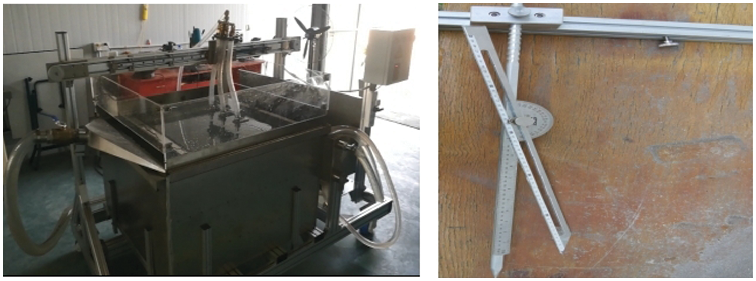
Figure 1: The scouring test bench and measuring tools
The test uses non-viscous and non-uniform sand particles. Table 1 shows the size of the sand particles, the characteristics of which are as follows: the density, the porosity, the underwater repose angle and the critical shields number were 2650 kg/m3, 0.5, 45°, and 0.04, respectively. Furthermore, considering the requirements of the subject and the existing data, the flow rate of ambient water was set to 0.5 m/s. Moreover, the depth of the brush pit needed to be more than 10 cm. The pit efficiency of an inclined jet was confirmed to be higher than that of a vertical jet. In a previous study carried out by the researcher, the optimum efficiency was obtained at an inclined angle of 15–20 and the nozzle diameter (d) of 3 mm. Previous studies show that when the distance of the jet target is more than 30 times of the nozzle diameter (30 d), the depth and the diameter of the scour pit are small and large, respectively. On the other hand, the short distance of the jet target (less than 20 d) indicates that the depth and diameter of the scour pit are large and small, respectively. Yet, the average distance of the jet target (between 20d and 30d), designates the relatively large depth and diameter of the flushing pit, i.e., a better flushing effect. Accordingly, the chapter analyzes the adaptability of the model test and simulation experiment when the target distance is 0.1 m and the jet speed is 3 m/s.

The calculation was basically consistent with the pool model test. Accordingly, fluid software of FLOW-3D was selected for carrying out the numerical simulation of scouring. Sand erosion model, viscosity and turbulence model and gravity and non-intrinsic reference frame were used as the physical models for the numerical calculation of water jet erosion [16]. Moreover, to solve the two-dimensional hydrodynamic characteristics of incompressible viscous fluid, RANS Navier Stokes governing equations and RNG k-ε Turbulence Model were used. FAVOR (Fractional Area Volume Obstacle Representation) was also applied to make sure if the mesh was completely resolved. In the calculation, implicit equation was used to reduce the numerical fluctuation. The appropriate time step was selected based on the stability, accuracy and efficiency of the solution. While the initial time step was determined as 0.01 s, the minimum was 1E-8. In the separation solver, simple is chosen for the pressure-velocity coupling scheme. Since the simulation model was relatively simple, the uniform mesh quadrilateral format was adopted, with the aspect ratio of 1 for the mesh [17]. In the numerical simulation test, three types of grids with the lengths of 0.0005, 0.001 and 0.002 were selected for the sensitivity test. The results of the test demonstrated the relatively poor numerical simulation structure of 0.002. Moreover, the accuracy was shown to be low, the contour shape was fuzzy, and the results of 0.001 and 0.002 grids were close. Therefore, in order to save the calculation time, the 0.001 grid was used for the numerical simulation. In addition, the 0.0005 grid was adopted for the nozzle (see Table 2). The jet erosion model simulated and predicted the sediment movement, convection and deposition, the main parameters of which were set as the following. 1) Since gravity needs to be considered during scouring, Gravity Model was selected for the simulation; 2) RNG k-ε Turbulence model was selected as the viscosity and turbulence model; 3) The sediment erosion model was set in accordance with the parameters of sand particles in the test; 4) Such factors as calculation accuracy, time, and area, as well as the nozzle needs to be locally encrypted around. Moreover, the number of grids in the calculation area was 19932 (including 12 grids for nozzles); and 5) To ensure the fixed height of the fluid as well as the free flow of the water in both directions, as shown in Fig. 2, the left and right boundaries were set as outflow, it was pressurized on the top which could change when simulating seabed scouring, the bottom was a wall, and the nozzle outlet was the velocity boundary, with the other parts being symmetrical. The analysis revealed that the geometry of the model meets the boundary conditions and the selected mesh converges.


Figure 2: The schematic diagram of simulation
Generally speaking, the shape of the scouring pit, including its depth, width and mound height of the deepest pit is of considerable importance. Therefore, the numerical simulation selects the data after suspended sediment sedimentation as the research object.
In the process of simulation calculation, firstly, the calculation and simulation were carried out using computer. This was done in accordance with the set time and boundary conditions. Then, when the calculation time was extended, the calculation continued until the suspended sediment settled and the jet velocity turned 0 s/m. The reliability of water jet scouring was directly determined by the accuracy of hydrodynamic calculation. Moreover, to ensure the reliability, the parameters of the simulation platform were debugged and verified using the measured data of pool model test.
Fig. 3 shows the comparison of simulation model and test results when the velocity of the nozzle jet is 3 m/s. The comparison demonstrates the evolution characteristics of the two-dimensional profile of the jet scouring sand pit in 10, 20, 30 and 40 s. As can be seen in Fig. 3, while the left side shows the numerical simulation results, the right side is the two-dimensional diagram of test scouring. It can be observed that the contour shape and its development trend of the comparative model test and simulation are almost consistent. This can verify the effectiveness of the model and the credibility of the simulation results.
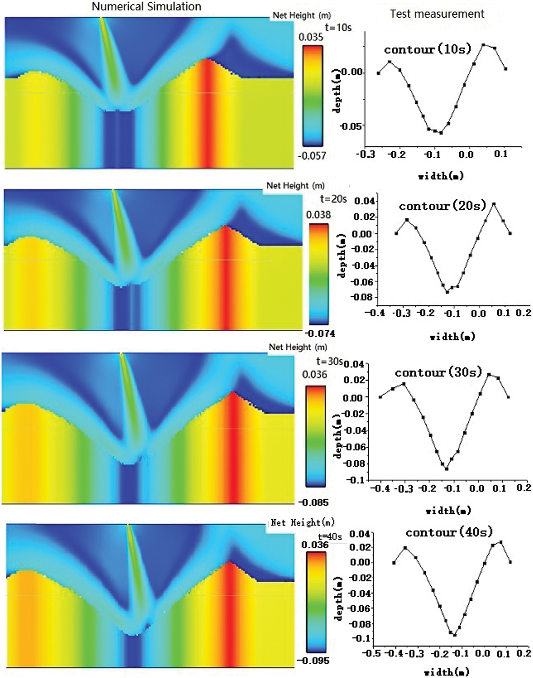
Figure 3: Evolution of scour pit profile with time
Compared with an experiment, enjoy being considerably purposeful and applicable. Accordingly, simulations have an exceptional role in theoretical and experimental research, particularly when studying certain change features and recurring calculations. Hence, to study the influencing characteristics of jet on scour pit, numerical simulation was carried out based on the physical test model.
4 Simulation and Analysis of Inclined Jet Erosion in Flow Environment
To further analyze the influence of the velocity of ambient water on the inclined jet scour in submerged water jet, this study was based mainly on the invariability of target distance and nozzle. The jet ratio, i.e., the proportion of the velocity of the jet to that of the ambient water was identified. Moreover, the influence of velocity and the direction of water environment on scouring were studied. These are in the condition of different jet ratios and seek the best scouring efficiency of jet in a certain water environment. Consequently, the environmental water flow velocity of 0.5 m/s and the scouring time of 20 s were set as the initial conditions of the simulation, which were simulated and calculated separately under different conditions of flow direction, jet angle and jet ratio. The results were employed to study the influence of the jet ratio on scour pit. As shown in Fig. 4, for the convenience of analysis, a and b were defined as the downstream direction and the countercurrent direction, respectively. The simulation calculation was carried out for 24 times under different working conditions (see Table 3). In addition, the results of the calculation were processed in flow sight.
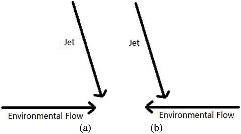
Figure 4: Schematic diagram of jet and water flow direction

“Packed sediment net change selected” is selected from the geometry list and the probe is drawn on “the isosurface list” where the depth and width of scour pits can be displayed at different positions. Finally, the Origin Software was used to analyze the data obtained from the scour pits. Figs. 5–8 show the contour of simulated scour pit under different working conditions. In order to improve operational efficiency, the best scouring mode is needed to be determined. In other words, it is suggested that the volume of scouring pit is the largest under the same conditions. In this study, since the two-dimensional model of simulation was used, the volume was represented by the scour pit area below the sand bed plane. In addition, to determine the influence of ambient water velocity on the inclined jet, the simulation of an inclined jet scour in the static environment is increased. The scour pit value was obtained when the value of the y-axis was less than 0. As an example and as shown in Fig. 9, let us take the jet ratio as 6, the movement direction of ambient water as countercurrent and the injection inclination angle as 10°. Table 3 demonstrates the calculation of the scour pit area from the simulation conditions, the values of which are shown in Table 4. Also, Figs. 10–12 illustrate the comparison and analysis of the values using Origin Software.
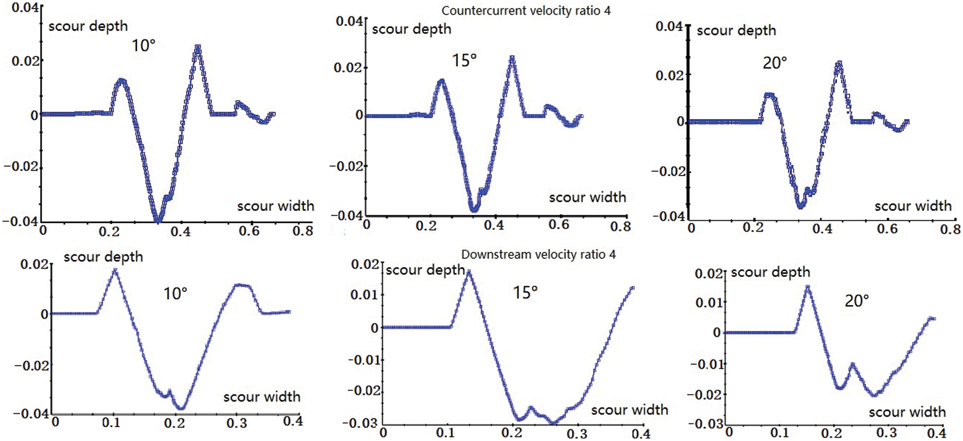
Figure 5: The scour pit profile with jet ratio of 4
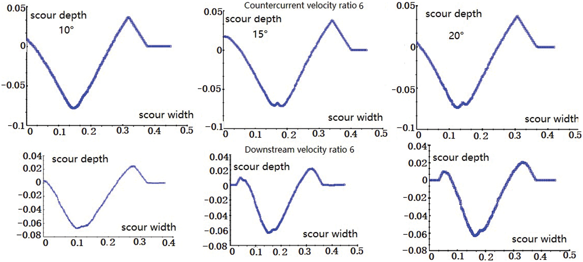
Figure 6: The scour pit profile with jet ratio of 6
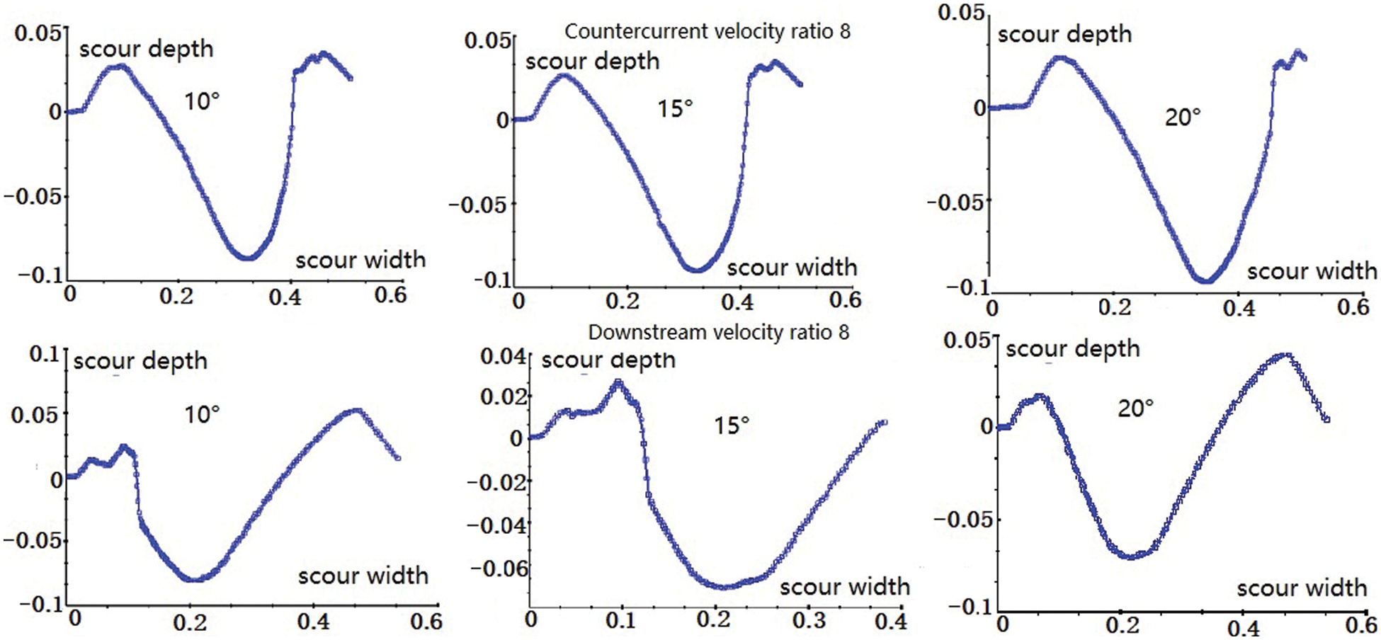
Figure 7: The scour pit profile with jet ratio of 8

Figure 8: The scour pit profile with jet ratio of 10
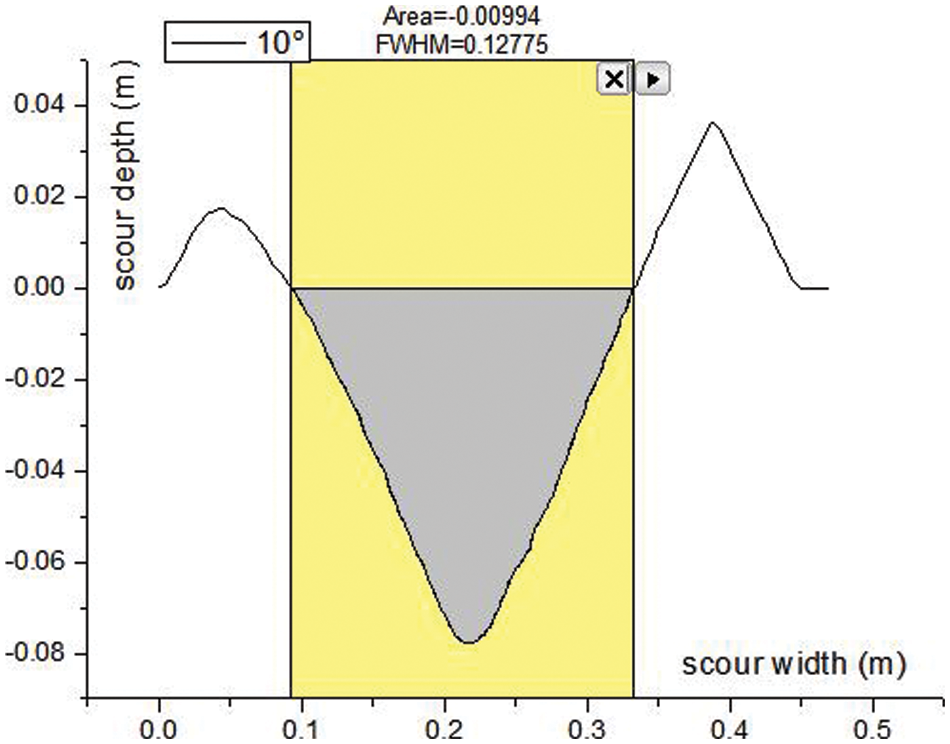
Figure 9: The scour pit area with y axis less than 0

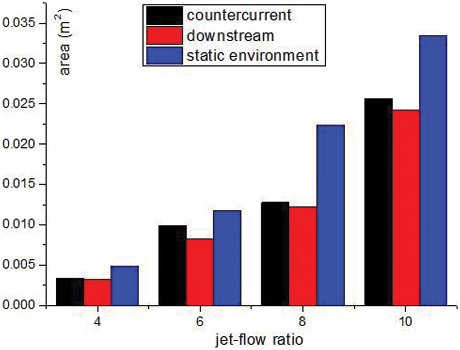
Figure 10: The area of scour pit with inclination of 10°
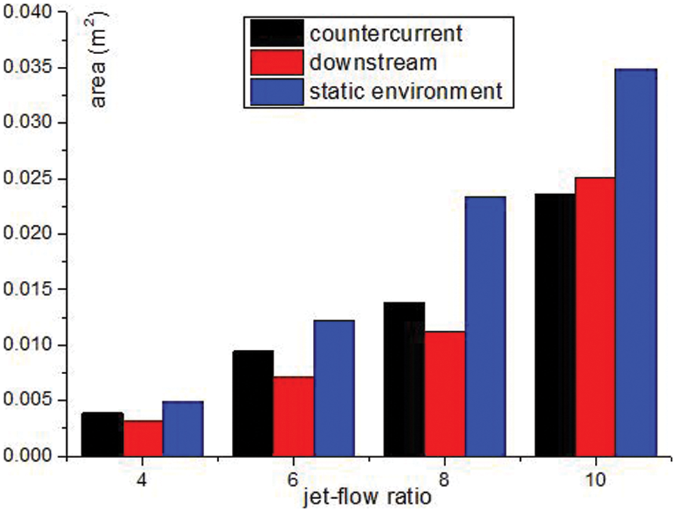
Figure 11: The area of scour pit with inclination of 15°
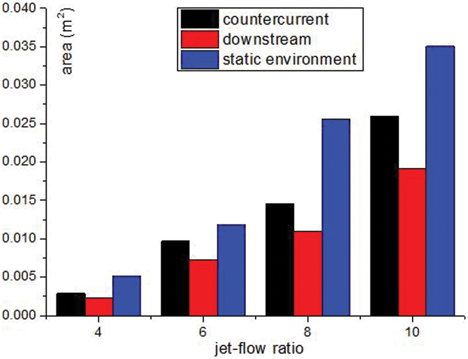
Figure 12: The area of scour pit with inclination of 20°
Accordingly, the following conclusions are drawn:
1) At the same jet velocity, the largest scouring area is obtained when the ambient water velocity is 0. This is due to the interference of the ambient water flow with the jet and the consequent weakening of the ability of the jet to scour the bunker.
2) Under the countercurrent condition, while a small level of the jet ratio leads to the higher level of the dunes on the right side of the scour pit, an increase in the ration leads to an increase in the level of the dunes on the left side. On the other hand, under the downstream condition, the dunes on the left and the right sides are higher when the jet ratio is small and when there is an increase in the jet ratio, respectively. This phenomenon is caused by the coupling between the reflected flow formed by the jet impinging on the sand surface and the ambient water flow.
3) Under the same condition of the jet ratio, the flow velocity of the ambient water leads the larger area of scour pit on the countercurrent condition than that of the downstream. Accordingly, there is relatively a large velocity between the ambient water and the component of the jet in the horizontal direction. This makes the suspended sand to flow more easily with the ambient water, and as a result, to increase the area of scouring pit. However, the interaction between the movement of ambient water and jet velocity causes a change in the center of the jet, i.e., the angle of jet scouring might be affected. Therefore, under the same jet ratio, the variation of scour area is quite complex for different jet inclination angles.
The application of the two-dimensional RNG k-ε Turbulence model and FAVOR Technology provided useful information about the influencing characteristics of submerged inclined jet scouring sand bed in the ambient water flow. FLOW-3D was used to simulate the motion trajectories of different sand radius under the action of the jet. Physical model tests confirmed and corroborated the efficiency of the numerical simulation. The results revealed the consistency of the pit contour shape of physical model test with the simulation results. Moreover, the scouring simulation was frequently carried out under different working conditions, the results of which were post processed using powerful simulation software.
The results demonstrated that the environmental water flow has a significant impact on the jet scouring behavior. In other words, the scouring capacity of water jet is remarkably weakened by the water flow. Furthermore, under the same conditions, better results were obtained for countercurrent scouring than the downstream. Finally, the findings of the present study provide theoretical support for operation of submerged water jet.
Funding Statement: This work is supported by National Nature Fund of China (52071091) and the Key Laboratory of Expressway Construction Machinery of Shanxi Province which is gained by Zhang (300102259512).
Conflicts of Interest: The authors declare that they have no conflicts of interest to report regarding the present study.
References
1. Hou, J., Zhang, L., Gong, Y., Ning, D., Zhang, Z. (2016). Theoretical and experimental study of scour depth by submerged water jet. Advances in Mechanical Engineering, 12(8), 125–132. DOI 10.1177/1687814016682392. [Google Scholar] [CrossRef]
2. Li, C., Mo, Z., Jiang, H., Yang, F. (2022). An experimental and numerical study on the cleaning of pleated bag filters using Low-pressure pulsed-jets. Fluid Dynamics & Materials Processing, 18(1), 29–39. DOI 10.32604/fdmp.2022.017947. [Google Scholar] [CrossRef]
3. Mazurek, K. A., Hossain, T. (2007). Scour by jets in cohesionless and cohesive soils. Canadian Journal of Civil Engineering, 34(6), 744–751. DOI 10.1139/L07-005. [Google Scholar] [CrossRef]
4. Rajaratnam, N., Mazurek, K. A. (2003). Erosion of sand by circular-impinging water small tailwater. Journal of Hydraulic Engineering, 129(3), 225–229. DOI 10.1061/(ASCE)0733-9429(2004)130:7(725). [Google Scholar] [CrossRef]
5. Rajaratnam, N., Beltaos, S. (1977). Erosion by impinging circular turbulent jets. Journal of the Hydraulics Division, 103(10), 1191–1205. DOI 10.1061/JYCEAJ.0004852. [Google Scholar] [CrossRef]
6. Aderibigbe, O. O., Rajaratnam, N. (1996). Erosion of loose beds by submerged circular impinging vertical turbulent jets. Journal of Hydraulic Research, 34(1), 19–33. DOI 10.1080/00221689609498762. [Google Scholar] [CrossRef]
7. Mih, W. C., Kabir, J. (1983). Impingement of water jets on non-uniform stream bed. Journal of Hydraulic Engineering, 109(4), 536–548. DOI 10.1061/(ASCE)0733-9429(1983)109:4(536). [Google Scholar] [CrossRef]
8. Taştan, K., Koçak, P. P., Yildirim, N. (2016). Effect of the bed-sediment layer on the scour caused by a Jet. Arabian Journal for Science and Engineering, 41, 4029–4037. DOI 10.1007/s13369-016-2093-7. [Google Scholar] [CrossRef]
9. Beltaos, S., Rajaratnam, N. (2010). Impingement of axisymmetric developing jets. Journal of Hydraulic Research, 15(4), 55–59. DOI 10.1080/00221687709499637. [Google Scholar] [CrossRef]
10. Naoki, T., Yutaka, S., Toshinori, K. (2021). Scour reduction in sand beds against vertical jets by applying sheet-like countermeasures. Marine Georesources and Geotechnology, 39(6), 649–658. DOI 10.1080/1064119X.2020.1737893. [Google Scholar] [CrossRef]
11. Qi, M. L., Fu, R. S., Chen, Z. C. (2005). Study on equilibrium depth of jet erosion. Hydrodynamic Research and Progress, 20(3), 368–372. DOI 10.3969/j.issn.1000-4874.2005.03.014. [Google Scholar] [CrossRef]
12. Huai, W. X., Wang, Z. W., Qian, Z. D. (2012). Numerical simulation of two-dimensional vertical jet scouring on sandy riverbed. Science China Technological Sciences, 1, 72–81. [Google Scholar]
13. Qian, Z. D., Hu, X. Q. (2011). Numerical simulation of submerged jet erosion based on euler model. Science China Technological Sciences, 41(4), 419–425. DOI 10.1088/0253-6102/55/2/31. [Google Scholar] [CrossRef]
14. Edelbauer, W. (2017). Numerical simulation of cavitating injector flow and liquid spray break-up by combination of Eulerian–Eulerian and volume-of-fluid methods. Computers and Fluids, 4(10), 82–89. DOI 10.1016/j.compfluid.2016.11.019. [Google Scholar] [CrossRef]
15. Hirt, C. W., Sicilian, J. M. (1985). A porosity technique for the definition of obstacle in rectangular cell meshes, pp. 1–19. Washington: The National Academies Press. [Google Scholar]
16. Farizan, A., Yaghoubi, S., Firoozabadi, B. (2019). Effect of an obstacle on the depositional behaviour of turbidity currents. Journal of Hydraulic Research, 57(1), 75–89. DOI 10.1080/00221686.2018.1459891. [Google Scholar] [CrossRef]
17. Du, X., Liu, M., Sun, Y. (2022). Optimization of the internal circulating fluidized bed using computational fluid dynamics technology. Fluid Dynamics & Materials Processing, 18(2), 303–312. DOI 10.32604/fdmp.2022.016242. [Google Scholar] [CrossRef]
Cite This Article
 Copyright © 2023 The Author(s). Published by Tech Science Press.
This work is licensed under a Creative Commons Attribution 4.0 International License , which permits unrestricted use, distribution, and reproduction in any medium, provided the original work is properly cited.


 Submit a Paper
 Propose a Special lssue
 View Full Text
 Download PDF
 Downloads
 Citation Tools