
 Submit a Paper
 Propose a Special lssue
 Open Access
ARTICLE
Optimization of Control Loops and Operating Parameters for Three-Phase Separators Used in Oilfield Central Processing Facilities
Anton Oilfield Services (Group), Ltd., Beijing, 100102, China
* Corresponding Author: Yaqiao Li. Email:
(This article belongs to the Special Issue: Advanced Oil and Gas Transportation and Treatment Technologies)
Fluid Dynamics & Materials Processing 2023, 19(3), 635-649. https://doi.org/10.32604/fdmp.2022.020633
Received 04 December 2021; Accepted 12 January 2022; Issue published 29 September 2022
 View Full Text
 Download PDF
Abstract
In this study, the Stokes formula is used to analyze the separation effect of three-phase separators used in a Oilfield Central Processing Facility. The considered main influencing factors include (but are not limited to) the typical size of oil and water droplets, the residence time and temperature of fluid and the dosage of demulsifier. Using the “Specification for Oil and Gas Separators” as a basis, the control loops and operating parameters of each separator are optimized Considering the Halfaya Oilfield as a testbed, it is shown that the proposed approach can lead to good results in the production stage.Keywords
Phase separation technology is widely used in the petroleum and petrochemical industry [1,2], and the three-phase separator is a commonly used equipment in oilfield central processing facilities (CPFs). The main functions of CPFs include collecting the produced fluid from oil wells, separating the well stream into three phases, namely, oil, gas, and water, and treating them using physical and chemical methods, and transporting the products that meet the standards.
The Halfaya oilfield has an area of 239 square kilometers and recoverable reserves of 4.1 billion barrels and is located in the Missan Province, Southeast of Iraq. The designed crude oil capacity of one CPF of the Halfaya oilfield is 100,000 to 120,000 barrels per day. The processes carried out in the oilfield include oil, gas, and water treatment, oil and gas transportation, chemical injection, heating of medium heaters, and the use of instrument air and nitrogen systems and firefighting systems in the CPF. A distributed control system (DCS) is used to comprehensively monitor the production processes, and to collect, analyze, and manage the operating parameters of all the equipment in the CPF.
In this study, the Stokes’ formula was used to analyze the factors influencing the separation effect of the three-phase separator. The control loops and operating parameters of the separator used in a DCS were optimized according to the “Specification for Oil and Gas Separators.”
2 The Composition and Control Principle of DCS
DCS is an automation system commonly used in CPFs. It exhibits characteristics such as flexibility, openness, reliability, coordination, easy maintenance, and complete control of functions [3]. As shown in Fig. 1, the hardware of a DCS generally includes a central processing unit (CPU), redundancy, communication module, input/output (I/O) module, and power module. Its working mode is defined as follows: various parameters in the process of production, such as temperature, pressure, flow, and liquid level, are collected and converted into electrical signals, using the transmitters set on the equipment. Subsequently, the electrical signals are sent to the CPU of the DCS to be processed by the input module AI/DI. The output is converted back into electrical signals by the output module AO/DO and sent to the actuator which controls the control valve and pump. The state of the equipment is controlled by the opening and closing of the control valve, and the start–stop of the pump [4,5].
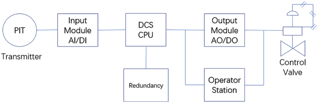
Figure 1: Schematic showing single control loop in a DCS
Through the man–machine interface of the DCS operator station (Fig. 2), the operators can identify the real-time production status, view alarm records and historical curves, and change the parameters set point. Moreover, all the controllers and pumps can be operated in the manual mode, if required.
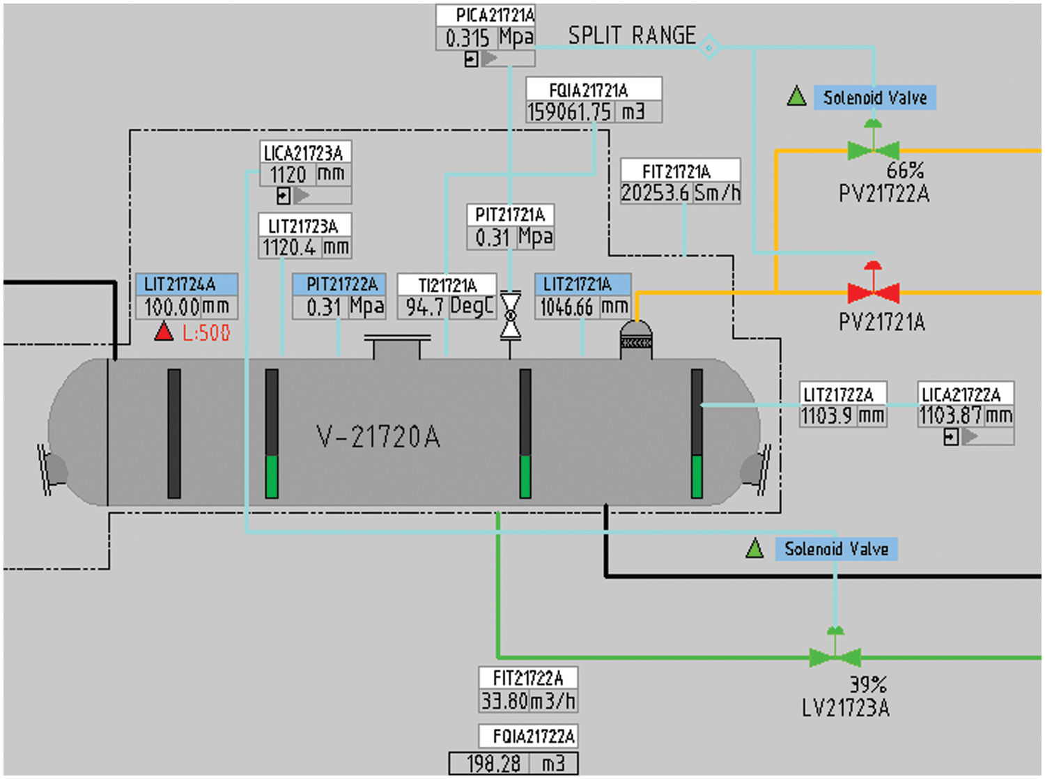
Figure 2: Man–machine interface of the DCS operator station
3 Separation Effect of Three-Phase Separator
The crude oil treatment process of the CPF considered in this study included a 1st-stage separator, oil–oil heat exchanger, oil–medium heat exchanger, 2nd-stage separator, dehydration pump, electrostatic dehydrator, electrostatic desalter, and gas boot.
There were four sets of 1st-stage separators and three sets of 2nd-stage separators, and all the three-phase separators had identical internal structures. Currently, due to the low water cut of the Halfaya oilfield, the 1st-stage separator was used for gas–liquid two-phase separation by connecting the oil outlet and water outlet, whereas the 2nd-stage separator was used for oil–gas–water three-phase separation.
3.1 Working Principle of Three-Phase Separator
The three-phase separator of the CPF was a horizontal gravity separator composed of an inlet separation section, gravity settlement section, oil chamber, and mist catcher, as shown in Fig. 3.
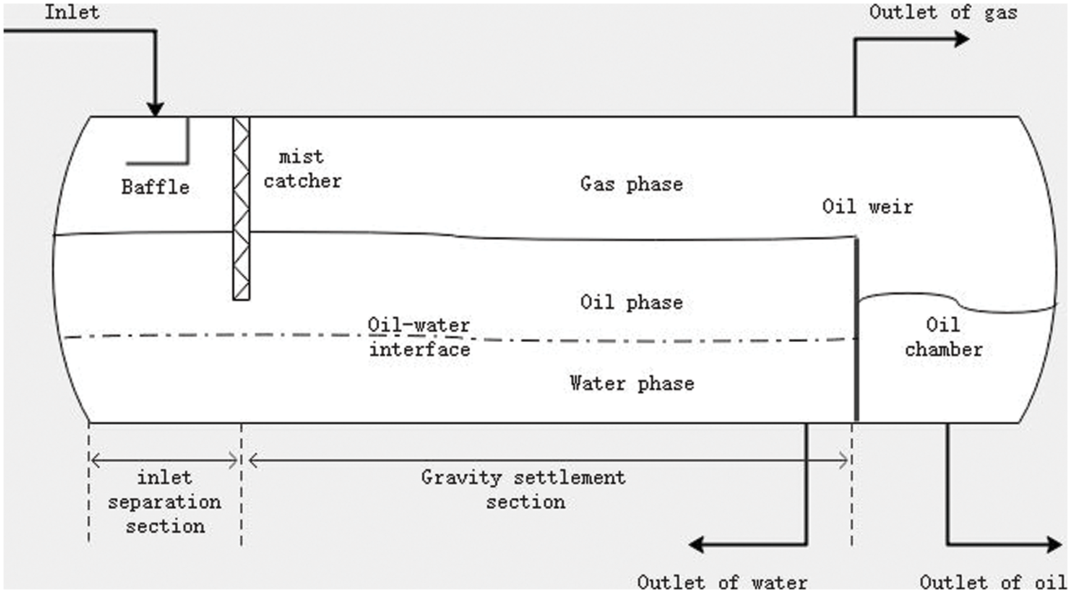
Figure 3: Structure of three-phase separator
Oil, gas, and water have different physical and chemical properties, such as density, and viscosity. The main separation methods of the three-phase separator are as follows:
(1) Collision separation [6]
Components, such as baffles, are installed in the inlet dividing section of the separator to collide with the incoming fluid, which leads to significant changes in the flow direction and speed, such that the separation occurs due to the difference in properties of gas and liquid phases.
Moreover, a mist catcher is installed in the upper part of the separator; when the gas passes through it, the droplets being carried over are intercepted and collected in it, and consequently fall to the liquid phase.
When the oil–water mixture flows in the gravity settlement section, the oil droplets float while the water droplets sink due to the difference in their densities, thus forming a continuous oil and water phase. The oil phase passes over the oil weir and enters the oil chamber, whereas, the water phase is discharged from the bottom outlet.
3.2 Factors that Influence Separation Effect
Several factors including particle size of oil and water droplets, residence time of fluid, emulsion, temperature of fluid, and dosage of demulsifier influence the separation effect in a three-phase separator [9,10].
3.2.1 Oil and Water Separation
Only the oil droplets float while the water droplets sink under the influence of gravity. Droplets can be considered as spherical particles, and the flow of oil and water in the three-phase separator can be regarded as laminar flow. According to the Stokes’ formula, the floating or sinking velocity of droplets can be expressed as follows [11]:
where v is the floating or sinking velocity of the droplets, ms−1; ρW and ρ0 are the density of water and oil, respectively, kg m−3; μ is the viscosity of the continuous phase, Pa⋅s; and d is the diameter of the droplets, m.
Residence time of the oil and water phase in three-phase separator can be expressed as follows:
where A is the cross-sectional area of the continuous phase, m2; le is the effective length of gravity settlement section, m; and Q denotes the flow rate of the continuous phase, m3 s−1.
According to Eq. (1), the larger the particle size of the droplet, the faster it floats and sinks, and the easier it is to be separated. Fig. 4 illustrates that there is a critical value for the separation of oil and water in the three-phase separator. Therefore, within the effective length of the settlement section, water droplets can pass through the entire oil phase and enter the water phase and oil droplets can pass through the entire water phase and enter the oil phase. In this case, the velocity of the droplet is the critical velocity, and the particle size of the droplet is the critical particle size. Smaller droplets having a velocity lower than the critical velocity or a particle size smaller than the critical particle size cannot be separated.
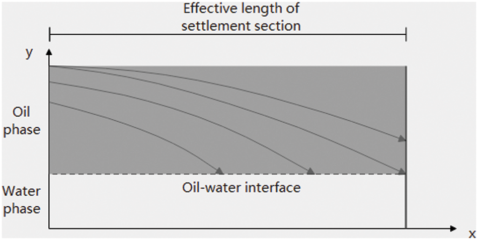
Figure 4: Sinking of water droplets in oil phase during laminar flow
Therefore, we assumed that the floating time of oil droplets is equal to the residence time of the water phase, and the sinking time of water droplets is equal to the residence time of the oil phase. Thus,
where vo and vw are the velocities of oil and water droplets, respectively, m s−1; ho and hw are the thicknesses of oil and water phase, respectively, m; and to and tw are the residence times of oil and water phases, respectively, s.
According to Eqs. (1)–(4), the minimum particle size of oil and water droplets that can be separated in the three-phase separator can be expressed as follows [12]. Droplets smaller than this size cannot be separated.
where do and dw denote the particle sizes of oil and water droplets, respectively, m.
Generally, the viscosity of oil phase is greater than that of water phase. Therefore, the sinking velocity of water droplets is greater than that of oil droplets, and the minimum particle size of oil droplets that can be separated is greater than that of water droplets. Resultantly, the separation of oil droplets from water is significantly easier than the separation of water droplets from oil.
In this study, the physical properties of oil, gas, and water, the flow rate, and other factors that affect oil and water separation in the three-phase separator were analyzed according to the size of separators.
The 1st-stage separator only separates gas and liquid, and has no continuous water phase due to the low water cut. Therefore, only the separation effect of water droplets in the oil phase needed to be considered, and the calculation results were as follows.
Fig. 5 shows that when the flow rate was 300 m3 h−1, with the increase in liquid level in the 1st-stage separator, the residence time of oil phase increased gradually, and the minimum particle size of water droplets that could be separated decreased gradually. However, when the liquid level was 1.1 m, with the increase in flow rate, the residence time of oil phase decreased steadily, and the minimum particle size of water droplets that could be separated increased steadily.
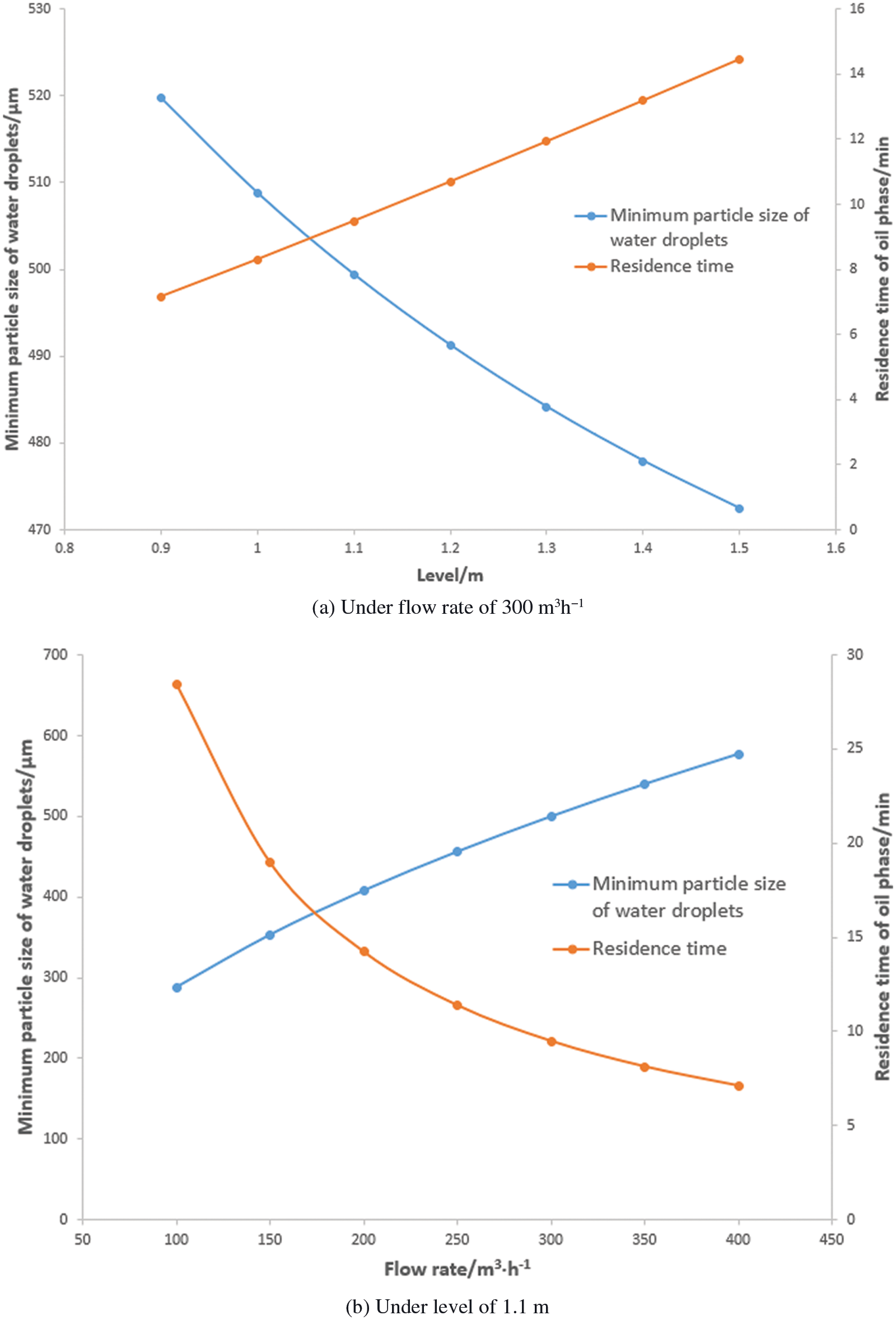
Figure 5: Separation effect of 1st-stage separator under different operating parameters (40°C)
In the 2nd-stage separator, the liquid level of the gravity settlement section was controlled by the height of the weir. The settlement section exhibited a continuous oil and water phase, thus the height of the oil–water interface also needed to be regulated. The calculation results indicated that the residence time of water phase in the 2nd-stage separator could be greater than 120 min. Under the current water cut of the oilfield and a flow rate of 300 m3 h−1, the minimum particle size of oil droplets that could be separated was below 10 μm; thus it could be ignored temporarily. The results are expressed as follows.
Fig. 6 shows that when the flow rate was 300 m3 h−1, with the rise in oil–water interface of the settlement section in the 2nd-stage separator, the residence time of oil phase decreased gradually, and the minimum particle size of water droplets that could be separated gradually decreased. When the oil–water interface was 0.8 m, with the increase in flow rate, the residence time of oil phase decreased steadily, and the minimum particle size of water droplets that could be separated increased steadily.
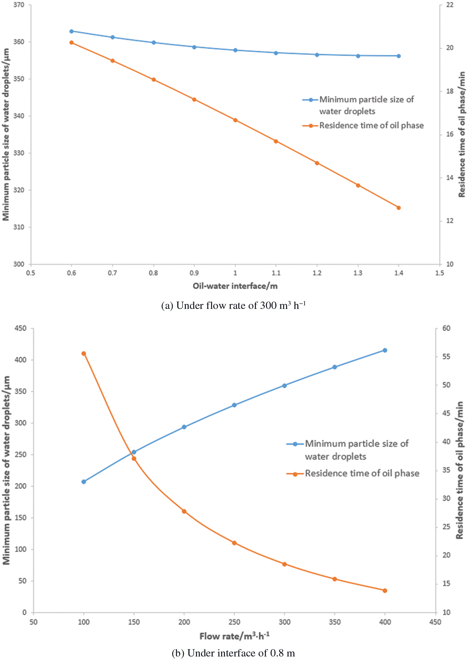
Figure 6: Separation effect of 2nd-stage separator under different operating parameters (95°C)
As the water cut of the oilfield was increased continuously, the oil–water interface was set to 0.8 m and the flow rate was set to 300 m3 h. The calculation of the 2nd-stage separator is as follows.
Fig. 7 shows that when other conditions remained unchanged, the residence time of oil phase in the 2nd-stage separator increased with the increase in the water cut; however, that of the water phase decreased rapidly. The minimum particle size of oil droplets that could be separated increased, whereas the minimum particle size of water droplets decreased.
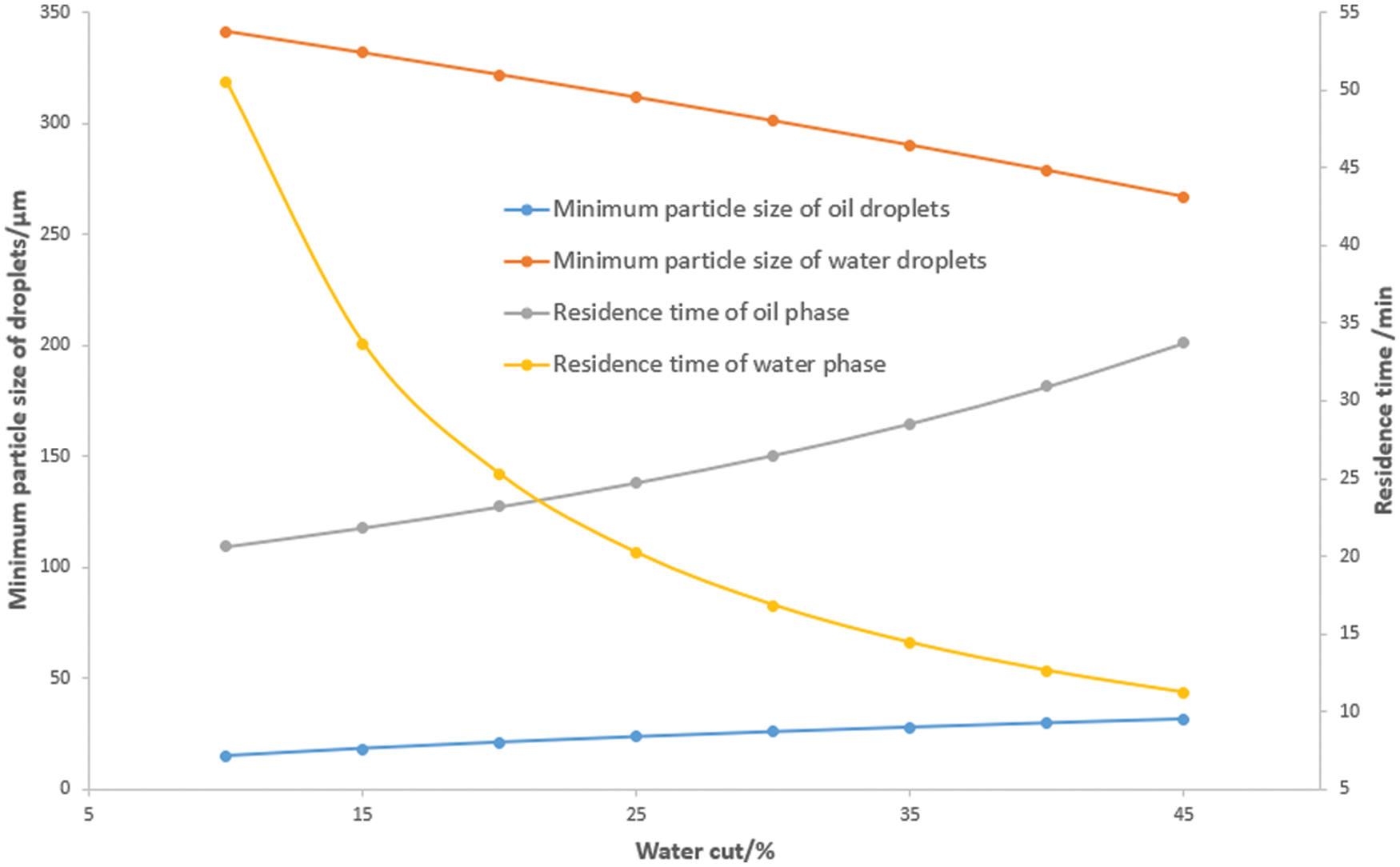
Figure 7: Separation effect of 2nd-stage separator under different water cut (95°C)
3.2.2 Gas and Liquid Separation
Generally, the flow of gas phase in a separator is complex, and includes laminar flow, transition flow, and turbulent flow. Therefore, the flow regime of gas must be considered.
To simplify the calculation, it is typically assumed that the droplet is spherical, there is no interaction force among the droplets, and the sinking velocity of the droplet is equal to the velocity when the buoyancy force and resistance are equal. The sinking velocity of droplets in the gas phase can be expressed as follows [13]:
where v is the sinking velocity of the droplet, m s−1; ρl and ρg are the densities of liquid and gas, respectively, kg m−3; d is the diameter of droplet, m; and CD denotes the drag coefficient.
The drag coefficient CD is related to the Reynolds number Re, and varies with the flow regimes. In laminar flow, CD = 24/Re and the Stokes’ formula is applicable; whereas, in transition and turbulent flows, the Stokes’ formula is not applicable.
In the actual production of CPF, the physical properties of the liquid and gas are significantly different; hence, the densities of oil and water are much higher than that of gas. Moreover, the gas space in the separator is equipped with a mist catcher which can easily separate gas and liquid in the separator.
According to the “Specification for Oil and Gas Separators” the allowable flow velocity of gas in a three-phase separator vg can be calculated using the following empirical formula [14]:
The constant K depends on the design and operating conditions of the horizontal separators, and its value can be (0.4−0.5) × (L/10)0.56, where L is the separator length.
In the separator, the gas flow rate Qg can be calculated using the allowable flow velocity of the gas, vg and the cross-sectional area of the gas space, Ag as follows:
Three-phase separators generally operate under a certain pressure, and the corresponding state equation of natural gas is represented as follows:
where p is the pressure of the gas, Pa; V is the volume of the gas, m³; Z is the compression factor; T is the temperature, K; n is the amount of substance of gas, mol; and R is the mole gas constant, J (mol K)−1.
Calculations based on relevant data indicated that the K-value for the three-phase separator in this CPF could be 0.37. The natural gas production of the 1st-stage separator could reach approximately 430,000 Sm3 d−1. When the pressure was 0.9 MPa, the allowable flow velocity of gas was approximately 4.37 m s−1, and the minimum cross-sectional area of gas space was approximately 0.127 m2. Furthermore, the gas production of the 2nd-stage separator could reach approximately 320,000 Sm3 d−1. When the pressure was 0.3 MPa, the allowable flow velocity of gas was approximately 7.59 m s−1, and the minimum cross-sectional area of gas space was approximately 0.152 m2.
Moreover, the cross-sectional areas of gas space in both 1st-stage and 2nd-stage separators were significantly higher than these values; thus the requirements of gas and liquid separation could be met.
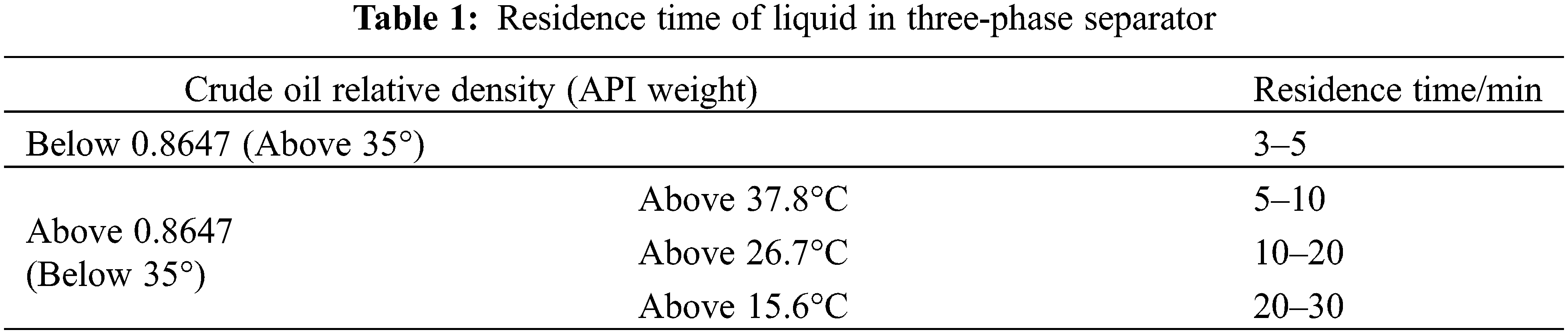
The above-mentioned analysis indicated that the longer the residence time of the fluid in the three-phase separator, the better was the separation effect of oil and water. The separation effect in the three-phase separator decreased with the reduction in the residence time of the fluid; however, the oil processing capacity of the CPF increased. Therefore, the residence time of fluid could be appropriately reduced if the separation effect was acceptable. According to the “Specification for Oil and Gas Separators,” the residence time of the fluid is shown in Table 1:
The viscosity of a liquid is affected by temperature. With increase in temperature, the kinetic energy of molecules increases, and the viscosity of the liquid decreases.
The Stokes’ formula shows that the velocity of droplets is inversely proportional to viscosity. With increase in temperature, the viscosities of both oil and water decrease, the floating and sinking velocities of droplets increase, and the minimum particle sizes of oil and water droplets that can be separated decrease. Therefore, temperature is an important factor affecting the separation of oil and water. If the temperature of fluid is too low, the separation effect in the three-phase separator is diminished.
A certain amount of emulsion is present in the fluid; it is produced in the well and enters the CPF through a pipeline. Therefore, a demulsifier is generally injected into the fluid to destroy the oil–water interface film and accelerate the separation of oil and water.
When the demulsifier concentration is too low, the demulsification effect is insufficient. However, when the demulsifier concentration is too high, the process cost increases, and secondary emulsification may occur. Therefore, the dosage of demulsifier must be determined according to the properties of the emulsion.
4 Control Loops and Operating Parameters
The CPF processes involve various operating parameters which can be divided into the following two categories: The first category includes important parameters related to quality, safety, and equipment protection, which must be monitored carefully and controlled regularly to keep them stable. Contrarily, the second category includes other parameters which are less important and only need to be monitored without any control or maintained within a certain range.
To reduce the impact of equipment caused by pressure changes, the equipment employed in CPF must be operated under stable pressure. Based on the analysis of factors that influence the separation effect together with the working mode of each separator in this CPF, the main control loops were selected, as shown in Fig. 8.
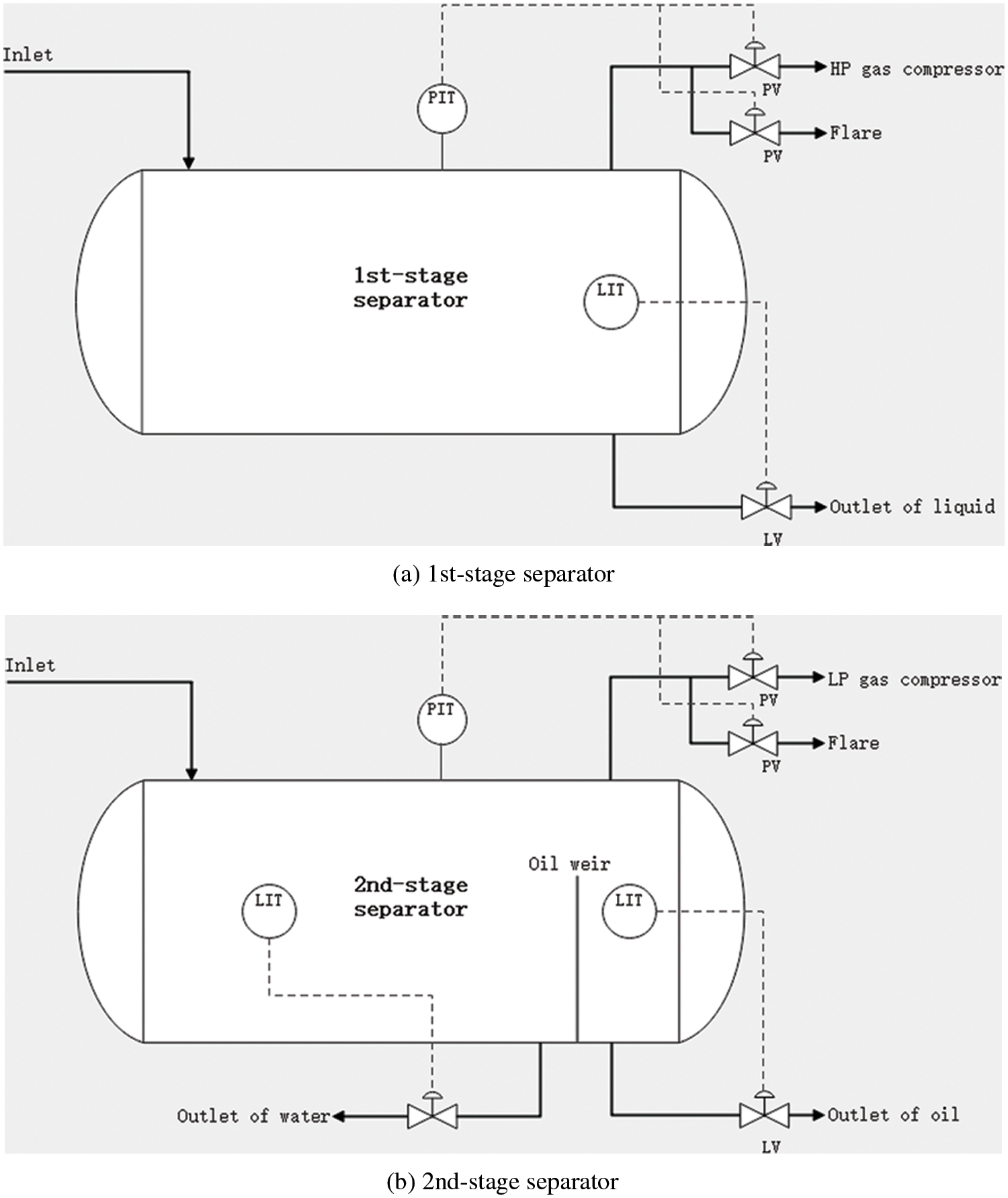
Figure 8: The main control loops of each separator in the DCS
In the 1st-stage separator, the selected main control loops included the pressure and liquid level of the separator. In the 2nd-stage separator, the main control loops selected were the pressure, temperature of the fluid, oil–water interface of the settlement section, and liquid level of the oil chamber.
Currently, the crude oil production of this CPF is approximately 120,000 barrels/day, with an incoming flow rate of 800 m3 h−1, a water cut of less than 10%, and a temperature of 37°C–42°C.
(1) Flow rate and dosage of demulsifier
Flow rate and dosage of demulsifier could be monitored in the DCS without control. The oil treatment process of this CPF is divided into three trains, and the crude oil is distributed through the inlet manifold into these trains. The average flow rate of each train was maintained within 200–300 m3 h−1. The dosage of the demulsifier was adjusted using the demulsifier dosing pumps in the laboratory according to the daily production, and was adjusted to 25–30 ppm.
(2) Control of pressure
Pressure of the separator was obtained using a pressure transmitter, and stratified control was performed using two pressure control valves by controlling the discharge of natural gas. Part of the gas was conveyed to the HP/LP natural gas compressor, and the remaining gas was conveyed to the flare.
To maintain the suction pressure collected by the compressors and the normal operation of downstream equipment in the oil processing, the pressure of the 1st-stage separator was set to 0.9 MPa, and the pressure of the 2nd-stage separator was set to 0.32 MPa.
(3) Control of liquid level and oil–water interface
The liquid level and oil–water interface of the separator were obtained using a level transmitter, and control was performed using level control valves by controlling the discharge amount of oil and water. To maintain safety, some space must be left in the case of an emergency, and the liquid level and oil–water interface must not be set too low or too high. Otherwise, cross-flow may occur among the oil, gas, and water, which may lead to poor oil/water treatment and cause serious accidents in certain cases.
According to the analysis, when the flow rate was 300 m3 h−1, the level of the 1st-stage separator could be controlled at 1.1–1.2 m, the oil phase residence time was 9–10 min, and water droplets having particle size greater than 500 μm in the oil phase could be separated. Furthermore, the oil–water interface of the 2nd-stage separator could be controlled at 0.8–1.0 m, the residence time of the oil phase was 16–17 min, and the residence time of the water phase was greater than 120 min. Water droplets having particle size greater than 360 μm in the oil phase, and oil droplets having particle size greater than 10 μm in the water phase could be separated. Additionally, crude oil in the 2nd-stage separator entered the dehydrator after being pressurized using the dehydration pump. To maintain the suction pressure of the dehydration pump, the level of the oil chamber in the 2nd-stage separator must be maintained above 1.0 m; however, it must not be set too high.
(4) Control of temperature
Notably, the temperature of the incoming fluid remains stable and compatible with the process; therefore, temperature control loop was not present for the 1st-stage separator. The temperature of the fluid entering the 2nd-stage separator was regulated using a temperature transmitter and temperature control valve set on the oil–medium heat exchanger.
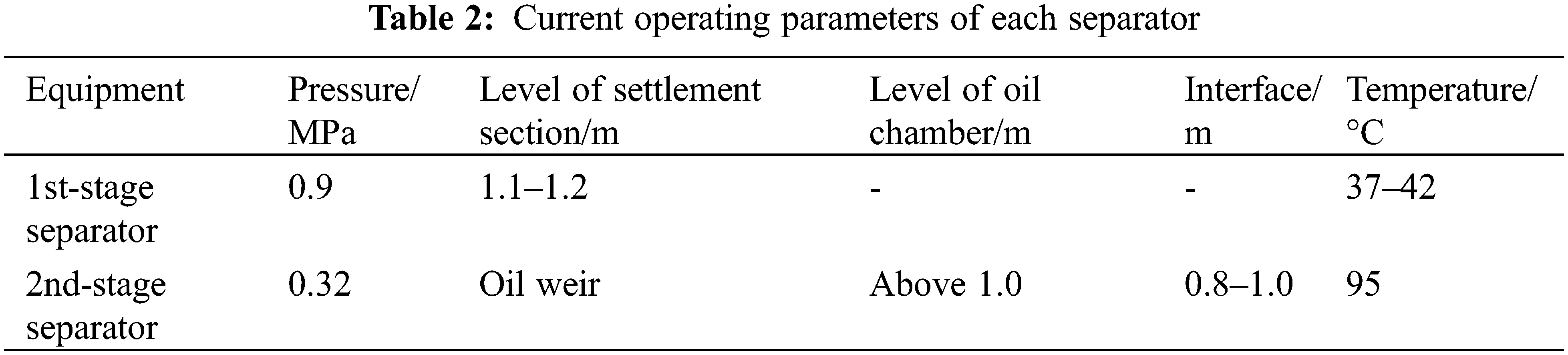
The temperature of fluid could be increased appropriately to improve the separation effect in the 2nd-stage separator. However, the operation of the dehydrator requires a high temperature, thus the temperature of the 2nd-stage separator was set to approximately 95°C, as shown in Table 2.
(5) Working mode
With the development of the oilfield, the water cut is expected to rise continuously in the future, which could result in a decrease in the separation effect of three-phase separators. When it rises to a certain level, the current working mode of the 1st-stage separator may not be able to meet the production requirements; thus changes must be made to the process. Water and oil must be discharged through different outlets, and the level of the settlement section must be regulated by the oil weir to realize the separation of oil, gas, and water. Simultaneously, the control loop of the oil–water interface must be added to the settlement section of the separator.
Figs. 9 and 10 exhibit the trends of parameters, such as pressure, liquid level of the 1st-stage and 2nd-stage separators of one train. The results show that the control of the DCS was stable and reliable. With large variation in incoming flow rate, the operating parameters of the separators stabilized, and the pressure and liquid level fluctuated within a very small range.
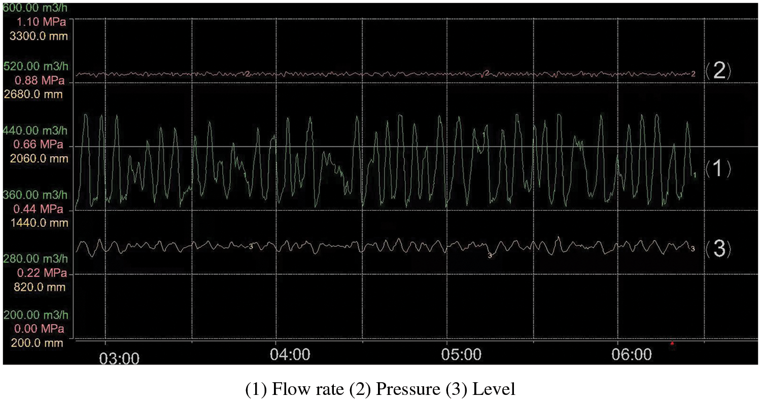
Figure 9: Control effect of 1st-stage separator of one train
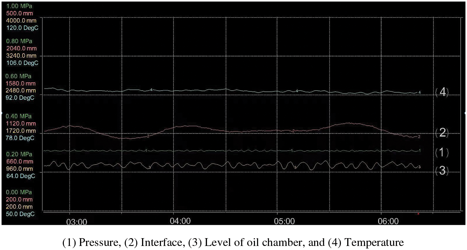
Figure 10: Control effect of 2nd-stage separator of one train
In production, after two stages of separation, the long-term sampling results of the 2nd-stage separator indicated that the water cut of the oil sample was below 2%, the content of crude oil in the water sample was below 100 ppm, and good separation effect was achieved
This CPF has been in production for many years and has maintained long-term stable operation under the control of the DCS. After the comprehensive treatment of all the separators, dehydrators, and desalters, the final water cut of crude oil was less than 0.2% and salt content was less than 20 ppm, which met the export standards.
6 Precautions during Operation
(1) To achieve the control of equipment using DCS, the following conditions must be fulfilled: the data collected must be accurate, the actuator must work normally, and the network communication must be normal. In actual production, particularly in harsh environments, all types of transmitters, control valves, or data transmission may be faulty, resulting in abnormal values and out-of-control conditions of some parameters. Accidents may occur in certain serious cases. Therefore, the DCS must be operated by experienced personnel to ensure precise evaluation, analysis, and judgment when alarms warn of risky factors and failures. Additionally, manual control of the process is required by DCS operators, and emergency repair is required by maintenance personnel.
(2) Transmitters and control valves must be tested, calibrated, and maintained regularly to reduce their failure rate.
(3) Operating parameters of the three-phase separator must be adjusted according to the actual production process. During certain well-washing operations, gas-lift operations, or new well-opening, a large amount of emulsion may enter the CPF and affect the stability of production, thus resulting in poor treatment. In this case, the dosage of the demulsifier must be increased in time, the oil–water interface must be adjusted, or the emulsion must be drained from the separator.
A distributed control system (DCS) can be used to comprehensively monitor the operating parameters and stably control the production process of a CPF, to achieve long-term, stable and safe operation.
The main factors influencing the separation effect in a three-phase separator include the particle size of oil and water droplets, residence time and temperature of fluid, and dosage of demulsifier. The control loops and operating parameters of the 1st-stage and 2nd-stage separators in a DCS were optimized, the efficiency of each separator was guaranteed, and good results were obtained.
Funding Statement: This study was supported by the Natural Science Foundation of Shandong Province (Grant No. ZR2021QE030).
Conflicts of Interest: The authors declare that they have no conflicts of interest to report regarding the present study.
References
1. Srinivasan, S., Saghir, M. Z. (2011). Impact of the vibrations on soret separation in binary and ternary mixtures. Fluid Dynamics & Materials Processing, 7(2), 201–216. DOI 10.3970/fdmp.2011.007.201. [Google Scholar] [CrossRef]
2. Cao, X., Bian, J. (2019). Supersonic separation technology for natural gas processing: A review. Chemical Engineering and Processing, 136, 138–151. DOI 10.1016/j.cep.2019.01.007. [Google Scholar] [CrossRef]
3. Mcphillips, T. M., Mcphillips, S. E., Chiu, H. J., Cohen, A. E., Kuhn, P. (2010). Blu-ice and the distributed control system: Software for data acquisition and instrument control at macromolecular crystallography beamlines. Journal of Synchrotron Radiation, 9(6), 401–406. DOI 10.1107/S0909049502015170. [Google Scholar] [CrossRef]
4. Sun, J., Liu, X. (2012). Research and application of control systems of auxiliary engines in cogeneration power station. Hypertension, 17(1), 39–44. [Google Scholar]
5. Johnson, E. N., Schrage, D. P. (2004). System integration and operation of a research unmanned aerial vehicle. Journal of Aerospace Computing Information & Communication, 1(1), 5–18. DOI 10.2514/1.4424. [Google Scholar] [CrossRef]
6. Gueguen, F., Nonell, A., Granet, M., Favre, G., Isnard, H. et al. (2010). Eu isotopic measurements with in situ Eu/Gd/Sm separation using O2 as a reactant gas in collision/reaction cell based MC-ICP-MS. Journal of Analytical Atomic Spectrometry, 25(2), 201–205. DOI 10.1039/B912605H. [Google Scholar] [CrossRef]
7. Tai, M. H., Gao, P., Tan, B., Sun, D. D., Leckie, J. O. (2014). Highly efficient and flexible electrospun carbon-silica nanofibrous membrane for ultrafast gravity-driven oil-water separation. ACS Applied Materials & Interfaces, 6(12), 9393–9401. DOI 10.1021/am501758c. [Google Scholar] [CrossRef]
8. Zhao, J., Wang, W., Ye, C., Li, Y., You, J. (2018). Gravity-driven ultrafast separation of water-in-oil emulsion by hierarchically porous electrospun poly (l-lactide) fabrics. Journal of Membrane Science, 563, 762–767. DOI 10.1016/j.memsci.2018.06.053. [Google Scholar] [CrossRef]
9. Oshinowo, L. M., Vilagines, R. D. (2020). Modeling of oil–water separation efficiency in three-phase separators: Effect of emulsion rheology and droplet size distribution. Chemical Engineering Research and Design, 159, 278–290. DOI 10.1016/j.cherd.2020.02.022. [Google Scholar] [CrossRef]
10. Chen, Y., Duan, H., Yu, F., Zhao, X., Han, X. et al. (2015). Parametric study of bubble kinematic behaviour in a centrifugal vacuum separator. Fluid Dynamics & Materials Processing, 11(2), 127–142. DOI 10.3970/fdmp.2015.011.127. [Google Scholar] [CrossRef]
11. Petan, S., Rusjan, S., Vidmar, A., Miko, M. (2010). The rainfall kinetic energy–intensity relationship for rainfall erosivity estimation in the Mediterranean part of Slovenia. Journal of Hydrology, 391(3–4), 314–321. DOI 10.1016/j.jhydrol.2010.07.031. [Google Scholar] [CrossRef]
12. Ngu, H., Wong, K. K., Law, P. L. (2012). Optimization of circular plate separators with cross flow for removal of oil droplets and solid particles. Water Environment Research, 84(4), 299–304. DOI 10.2175/106143012X13310630612646. [Google Scholar] [CrossRef]
13. Kuethe, D. O., Mcbride, A., Altobelli, S. A. (2012). Velocity of mist droplets and suspending gas imaged separately. Journal of Magnetic Resonance, 216, 88–93. DOI 10.1016/j.jmr.2012.01.006. [Google Scholar] [CrossRef]
14. Prikhodko, V., Chekmarev, S., Yarygin, V., Yarygin, I. (2006). Size and velocity distributions of droplets in a gas-droplet flow forming in a supersonic gas flow expanding into vacuum from a nozzle with near-wall liquid film. Doklady Physics, 51(2), 77–80. DOI 10.1134/S102833580602008X. [Google Scholar] [CrossRef]
Cite This Article
 Copyright © 2023 The Author(s). Published by Tech Science Press.
This work is licensed under a Creative Commons Attribution 4.0 International License , which permits unrestricted use, distribution, and reproduction in any medium, provided the original work is properly cited.
 Downloads
 Citation Tools