
 Submit a Paper
 Propose a Special lssue
 Open Access
ARTICLE
Modeling of Crack Development Associated with Proppant Hydraulic Fracturing in a Clay-Carbonate Oil Deposit
1 Perm National Research Polytechnic University, Perm, Russian
2 Perm State National Research University, Perm, Russian
3 PermNIPIneft Branch of LUKOIL-Engineering LLC, Perm, Russian
* Corresponding Author: Sergey Galkin. Email:
Fluid Dynamics & Materials Processing 2023, 19(2), 273-284. https://doi.org/10.32604/fdmp.2022.021697
Received 28 January 2022; Accepted 09 May 2022; Issue published 29 August 2022
 View Full Text
 Download PDF
Abstract
Survey and novel research data are used in the present study to classify/identify the lithological type of Verey age reservoirs’ rocks. It is shown how the use of X-ray tomography can clarify the degree of heterogeneity, porosity and permeability of these rocks. These data are then used to elaborate a model of hydraulic fracturing. The resulting software can take into account the properties of proppant and breakdown fluid, thermal reservoir conditions, oil properties, well design data and even the filtration and elastic-mechanical properties of the rocks. Calculations of hydraulic fracturing crack formation are carried out and the results are compared with the data on hydraulic fracturing crack at standard conditions. Significant differences in crack formation in standard and lithotype models are determined. It is shown that the average width of the crack development for the lithotype model is 2.3 times higher than that for the standard model. Moreover, the coverage of crack development in height for the lithotype model is almost 2 times less than that for the standard model. The estimated fracture half-length for the lithotype model is 13.3% less than that of for the standard model. A higher dimensionless fracture conductivity is also obtained for the lithotype model. It is concluded that the proposed approach can increase the reliability of hydraulic fracturing crack models.Graphic Abstract
Keywords
The development of oil fields of the Vereisky horizon (formation) of the Middle Carboniferous age is currently one of the promising areas of oil production. A feature of these objects is the high density of drilling and, accordingly, the high density of well logging studies. At the same time, deposits of the Vereisk formation are characterized by the layering of clay and carbonate rocks, low total reservoir thicknesses (3–6 m). Low well flow rates when using standard technologies of hydrochloric acid treatment [1–3] and radial opening of the reservoir [4,5] are the reasons for relatively low oil production volumes, which makes the development of these deposits unprofitable. Most of the wells that have uncovered these deposits exploit only the lower more productive oil layers. For these reasons, the development of Verey formation is carried out at a low pace. As a result, the Verey operational facilities in this area are the least developed, with a low share of accumulated oil production from the initial recoverable reserves (from 1% to 20%).
In recent years, the proppant hydraulic fracturing technology has shown high efficiency, consisting in the effect on the oil reservoir of the pressure created by the injection of fracturing fluids into the reservoir [6–8]. As a result of such an impact, a crack forms in the layer in the direction of the maximum horizontal stress σhmax and perpendicular to the minimum horizontal stress σhmin. The issues of the stress state of rocks and the development of fracturing processes under stress loads are considered in the works [9–11]. This paper considers vertical cracks, the formation condition of which is: σv > σhmax > σhmin, where σv is the vertical rock pressure. On the whole, the rock breaks along the planes of minimum strength with the formation of fracture zones in the layer. To prevent the effect of closing cracks, which occurs under the action of σhmin after pressure is removed, a proppant is injected into them together with the liquid, preserving the permeability of cracks, which is thousands of times higher than the permeability of the undisturbed formation. Hydraulic fracturing cracks become channels connecting the well with the distant formation part.
Prediction of the crack geometry development with calculation of fracture half-length, height and width are the most important factor in the final efficiency of the technology when planning hydraulic fracturing. The evaluation of the effect of these parameters on the amount of oil production is carried out by mathematical modeling [12]. As a result, an increase in the half-length of the crack leads to an increase in production, due to the large stimulated reservoir volume. All other things being equal. The fracture height and fracture width should be kept as constant as possible.
Comparison of the efficiency of proppant hydraulic fracturing with acid fracturing shows its greater efficiency. According to theoretical concepts, the fracture half-length during acid fracturing has to decrease due to relatively high leakage of the fracturing fluid and the high reaction rate of acid with rock [13]. This leads to a decrease in the coverage of the impact of the formation and especially to a faster decrease in the effect of the technology over time.
The analysis of the world experience shows that one of the actively developing modern areas of EOR is the integration of hydraulic fracturing with CO2 injection. Injection of carbon dioxide in the sub-surface oil-bearing formations not only improves the oil recovery but also reduces the carbon footprint from the planet. In [14,15], the issues of demonstration the simultaneous effect of multiple hydraulic fracture parameters and the CO2 injection volume for the directional EOR and CO2 trapping performance are considered. However, due to the high cost and the insufficiently high potential productivity of the wells of the Verey facilities in general, this technology is currently unprofitable and does not yet have experience in using Verey deposits.
The technology of standard proppant hydraulic fracturing is the main direction of the development of the Verey oil deposits for the research area in recent years is. In the last decade, various modifications of the use of proppant hydraulic fracturing in the development of Verey oil deposits have found the greatest use [16,17]. In all these areas, the high degree of development of reserves of deposits of the main oil horizons forces oil companies to switch to the development of significant residual recoverable reserves of the Verey deposits. The high technological efficiency of the use of proppant hydraulic fracturing in the near future should increase the demand for technology in the development of the Verey deposits and the other objects.
2 Construction of a Geology-Geophysical Model of Oil Deposits
The Verey deposits are characterized with a high degree of heterogeneity. The oil-bearing rocks are represented by limestones with different range of reservoir properties. As an example, a geology-geophysical section of the oil field well is given, in which the Verey formation (the interval from −906 to −922 m) is bounded from above and below by impermeable mudstones (Fig. 1).
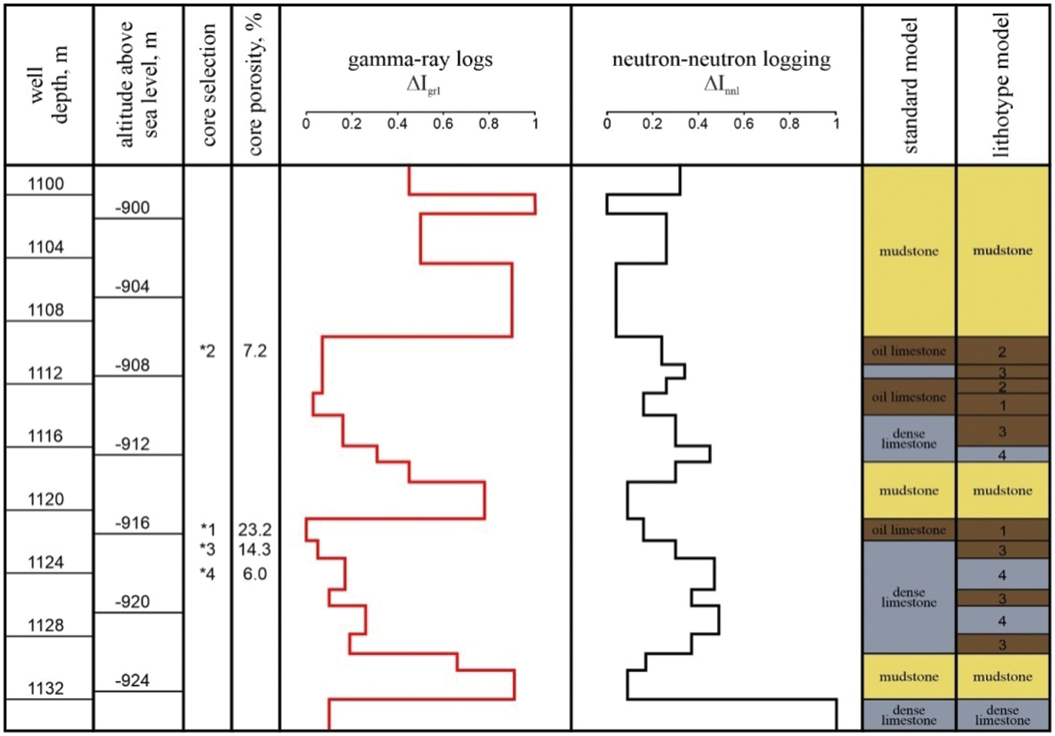
Figure 1: Geology-geophysical section of the well for the object
The allocation of oil-bearing intervals is estimated according to well logging methods of natural gamma-ray logging (ΔIgrl) and neutron-neutron logging (ΔInnl). Gamma logging evaluates the natural radioactivity of rocks and characterizes the clogging of layers, clearly separating carbonate rocks (ΔIgrl < 0.3) and mudstones (ΔIgrl > 0.5).
According to the core description, the carbonate rocks of the Verey deposits are represented by limestones. With a decrease in the readings of neutron-neutron logging, the volume hydrogen content of rocks increases. In the carbonate section, its minimum values are fixed for the most porous limestones, and its maximum values are the densest. For limestones of the Verey formation, the gamma logging readings are in the range ΔIgrl from 0 to 0.31, the neutron-neutron logging readings are in the range from 0.16 to 0.49. According to the data of the generalization of information on the object, reservoirs should have an open porosity (connected porosity) (Kp) of more than 7%. According to the core study data for compacted interlayers with ΔInnl > 0.45, the porosity of Kp = 6% is established, which shows the proximity of the porous space of intervals without signs of oil to that in reservoirs. In contrast, for the underlying layer of Bashkir age (below −924 m), a dense interlayer with the value ΔInnl = 1 was established, which shows the characteristic of the rock according to neutron-neutron logging with Кp < 1% (Fig. 1).
Based on the analysis of core and borehole geophysics studies in the section of carbonate rocks, four lithotypes can be distinguished, different in structural features. For lithotypes 1 and 2 the Kp estimate is accepted by well logging of more than 7%, and they are interpreted in the official calculation of reserves as oil-saturated reservoirs. Rocks of these intervals are detritus-foraminiferous and detritus-clump limestones.
According to the core study data, the first lithotype includes homogeneous clay-free intervals (ΔIgrl < 0.03) with the value of ΔInnl in the range from 0.16 to 0.17. The intervals of lithotype 2 are represented by alternating porous and dense rock varieties with thicknesses of 0.03–0.10 m. Well logging methods have a resolution of 0.1–0.2 m, i.e., they do not allow to isolate the interlayers of such small thicknesses. Therefore, for lithotype 2 well logging represents an average estimate. The values of ΔIgrl are in the range from 0.07 to 0.08. The values of ΔInnI are in the range from 0.24 to 0.26.
The Kp estimate for lithotypes 3 and 4 is taken by well logging less than 7%. The lithotypes 3 and 4 are interpreted in the official report as not containing industrial oil reserves. Basically, these intervals are represented by compacted limestones. However, the analysis of the core material shows the oil content of individual layers in lithotype 3. For this lithotype, the ΔIgrl readings are in the range from 0.05 to 0.19, which indicates a significantly different clay content in rocks. The ΔInnl values range from 0.30 to 0.37. The oil-bearing interlayers in lithotype 4 are completely absent. The increased readings of ΔIgrl (0.17–0.31) indicate significant clay participation in limestones, and the range of ΔInnl (0.45–0.49) indicates their strong compaction.
3 Results of Tomographic Core Studies
The X-ray tomography studies are carried out on the selected lithotypes, resulting in a digital image of the core formed in shades of gray color. The more porous rocks with the lowest X-ray density on tomographic sections correspond to the darkest background, and the densest ones are white. Computer modeling of the results is carried out in the Avizo Fire software package [18]. Examples of the use of tomographic method in the study of carbonate rocks are given in [19,20].
Initially, tomographic studies are carried out on a full-size core (100 mm in diameter), which allows to identify lithological inhomogeneities, fracture zones and areas of localization of cavities [21]. The tomograms are used to binarize the pore space in separate areas with a side of 1 cm × 1 cm × 1 cm. These tomographic studies allow to identify large lithological inhomogeneities of 0.2 mm or more in size. As a result, active development of cavernosity is established for lithotype 1, which, according to tomography data, is unevenly distributed in volume. According to the tomography of a full-size core of the lithotype 2, 76% of the volume is represented by porous rocks and 24% is represented by dense rocks. The proportion of potentially permeable rocks for lithotype 3 is reduced to 14%. Lithotype 4 is completely represented by dense rock without signs of decompression. It may be noted that the results of tomography of a full-size core in all cases have a low resolution, which is due to both the large size of the samples and the predominance of small voids in them.
To increase the resolution of tomographic studies, cubic core samples with a face size of 40 mm are made from the intervals of all 4 lithotypes. As a result, core samples homogeneous in lithological composition are obtained from the most permeable (lithotype 1) and dense (lithotype 4) parts of the geological section. The samples for the heterogeneous composition of lithotypes 2 and 3 are made in such a way that the contact between the permeable and dense parts is clearly traced in them. In all cases core extraction is carried out for the samples, after which the open porosity (Kp−liq) is calculated by the liquid method. As a result, the following values of Kp−liq for lithotypes 1–4 are obtained accordingly (%): 23.2; 7.2; 14.3 and 6.0.
Then tomographic studies are carried out on the extracted core cubes, the results of which are shown in Fig. 2.
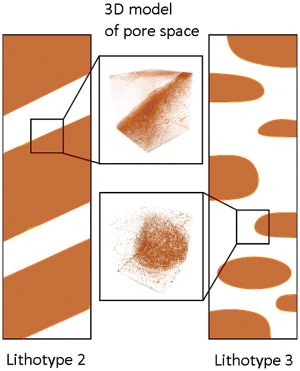
Figure 2: A schematic representation of the core structure for lithotypes 2 and 3 (3D models of the pore space by X-ray tomography are in the center)
Due to the reduction of the sample size the resolution of the model allowed to visualize voids with dimensions of more than 0.065 mm, along which fluids are mainly flowed.
Lithotype 1 is represented by a cavernous highly porous limestone. According to the tomography (Fig. 3a), almost the entire volume of its void space is visualized (Kp−tom = 22.1%). Lithotype 4 (Fig. 3d) is represented by limestone without large voids, for it the estimate of Kp−tom = 0.2% can be considered as a measurement error.
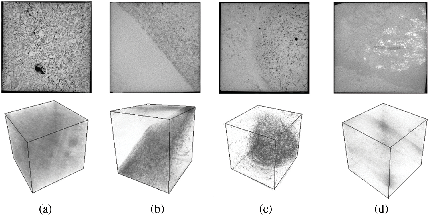
Figure 3: Tomographic sections (top) and 3D models (bottom) of the pore space on cubic samples for various lithotypes of rocks in the natural state: а–lithotype 1; b–lithotype 2; c–lithotype 3; d–lithotype 4
For lithotype 2, the proportion of the permeable part (Dper) in the sample volume is 13.8%, with a Kp−tom estimate of 2.7% (Fig. 3b). The boundary between the sections is sharp and even, which may correspond to the boundary between layers of permeable porous and dense clay limestone. The permeable part is composed of porous-cavernous organogenic-detritus limestone. For the dense part represented by fine-grained clay limestone the Kp−tom < 0.2%, which is lower than the method resolution.
The boundary between similar sites for lithotype 3 is not sharp, which allows us to make the assumption that the more porous sites (Dper = 67.3%) are inclusions inside a layer of dense limestone. The limestone structure can be called unevenly layered and spotted. Porous fragments are represented by rounded inclusions of organogenic limestone with elongated straight needle- and spindle-shaped pores located in the rock in different directions (Fig. 3c) and having, apparently, an organogenic origin. The Kp−tom for the permeable part is estimated at 3.6%, but for the dense part the pores have dimensions below the method resolution.
In the dense part of the samples (see Figs. 3c and 3d) voidness with dimensions greater than 0.065 mm is not established on tomograms. The reservoir properties and lithological features of the dense part of lithotypes 2 and 3 can be considered close to those of lithotype 4, and its porosity, taking into account the presence of smaller pores not accessible to tomography, can be estimated at 6%.
Table 1 summarizes the results of well logging, tomographic studies of a full-size core and manufactured cubes for all lithotypes.
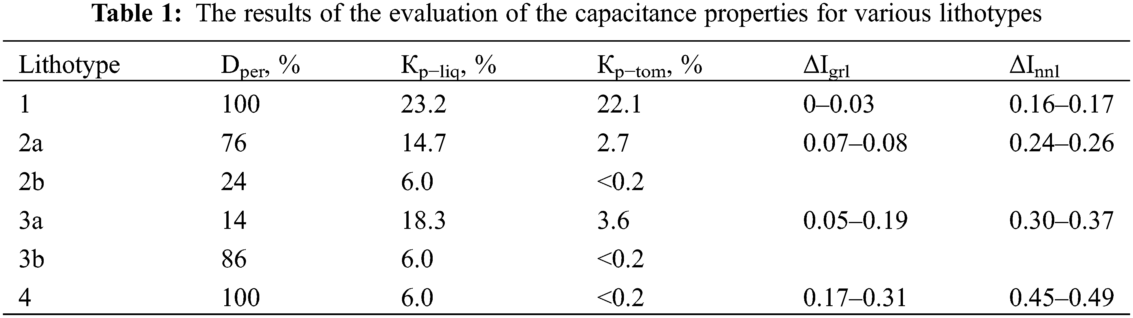
The differences in the structure of the reservoir space of inhomogeneous lithotypes 2 and 3 are especially contrasting, for which the Kp estimate in the volume of the permeable part of the rocks significantly exceeds 7%, which determines the possibility of obtaining oil inflows from the intervals of these lithotypes. Thus, 76% of the volume of rocks for lithotype 2 is represented by permeable limestones with Kp−liq = 14.7%, which makes their development especially promising.
The permeable part for lithotype 3 has even better reservoir properties, since it is represented by larger pores (Кp−tom = 3.6%). However, its share in the rock volume is insignificant (14%). Nevertheless, the characteristic elongated pores of lithotype 3 indicate the presence of a special hollow fractured space of rocks, the presence of which in the Verey formation is confirmed by the results of hydrodynamic studies of wells.
In particular, for some wells exploiting the Verey deposits a fracture of the pressure recovery curve was established, which is interpreted according to the Warren-Root model [22,23] as an effect on the flow of fracturing fluids of rocks. Generalization of information on hydrodynamic studies at the reservoir shows that the natural crack opening is quite low and does not exceed 10 μm. This allows us to explain the fact that for the area of the well from which the core is analyzed, according to the hydrodynamic studies, the reservoir works as a pore one without signs of the influence of cracks.
Nevertheless, the intervals of lithotype 3 can be attributed to potentially fractured, and the disclosure of natural cracks may increase during hydraulic fracturing. When hydraulic fracturing cracks are fixed with proppant, the likely scenario is to connect additional volumes of oil-containing rocks to the well operation.
Modeling of proppant hydraulic fracturing was performed in the “FracPro 2019” software package for two variants of the geological and mechanical model of an oil deposit. The first standard model provided for the currently existing idea of the homogeneous structure of carbonate rocks, while the lithotype model took into account the difference in the geomechanical properties of different lithotypes of rocks. For both models, the calculations also took into account the flow and elastic-mechanical characteristics of the Bashkir age formation (below a depth of 1132 m).
The “FracPro 2019” software package for calculating the development of a hydraulic fracturing crack provided for the introduction of initial technological information. It included the properties of proppant and breakdown fluids, as well as the dynamic characteristics of the treatment. The technological characteristics of hydraulic fracturing for standard and lithotype models were assumed to be the same. When constructing the models, BORPROP aluminosilicate proppant fraction 16/20 was used. The weight of the proppant was 30 tons, the maximum concentration was 800 kg/m3, the liquid flow rate was 3.8 m3/min. At the same time, the degree of conductivity restoration of the proppant slug after the disintegration of the gel, according to laboratory studies, was assumed to be higher than 65%.
Calculations were carried out for a water-based breakdown fluid WG-46 with a guar concentration of 3.0 kg/m3 and a linear gel viscosity from 18.6 to 20.8 MPa⋅s (at 21°C). The net pressure in the fracture during hydraulic fracturing in calculations was assumed to be 6.1 MPa, the breakdown fluid efficiency was 40%, the pressure of instant shut-in pressure (ISIP) was 10.1 MPa. In addition to the technological characteristics, the physical and chemical properties of fluids, well design data and reservoir pressure were also introduced into the model.
The flow properties of rocks in the calculated models are characterized by the coefficient of oil relative permeability (koil). The elastic-mechanical properties of rocks are taken into account by introducing the minimum horizontal stress profile, static Poisson’s ratio (vst), Young’s modulus (Est) and crack toughness (K1c) into the calculation. These characteristics for standard and lithotype models are given in Table 2.
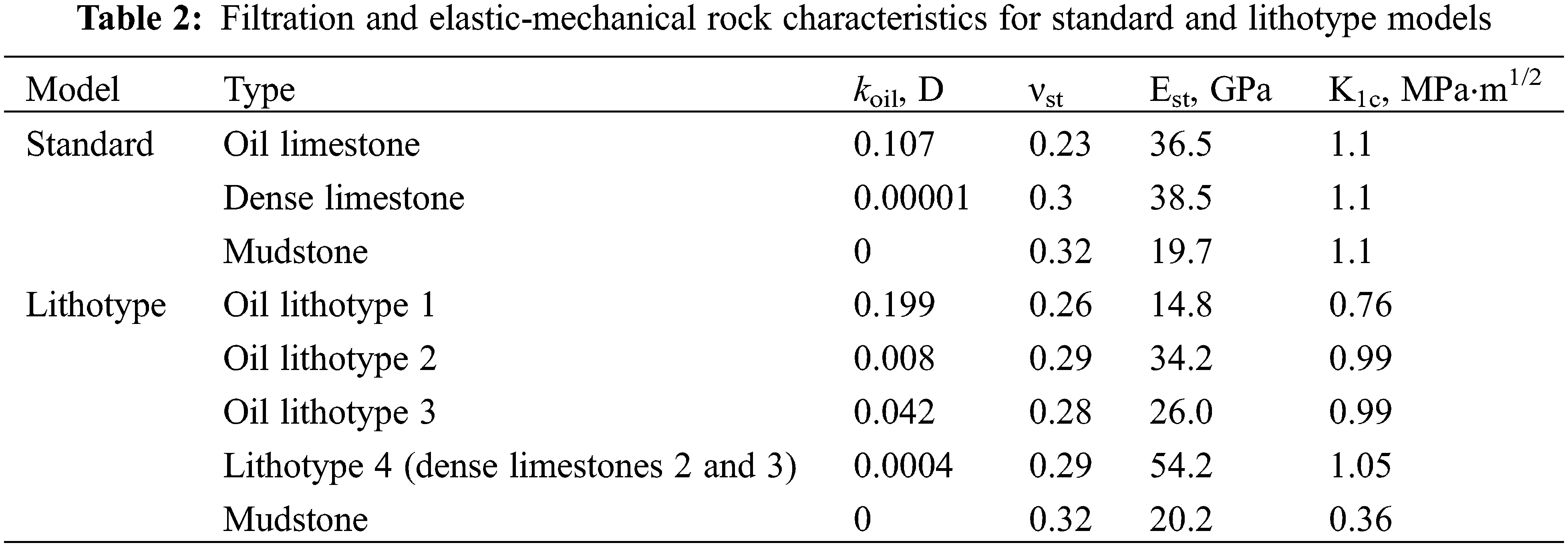
The standard model simplistically represents the Verey formation consisting of three types of rocks such as oil limestone, dense limestone and mudstone. All features in the model for these types of rocks are taken according to the current technological document for the development of oil fields (Table 2).
In lithotype model the differences in the properties of the oil and the dense part of the lithotypes 2 and 3 are taken into account. The structures of the intervals of lithotypes 2 and 3 are made in the calculations according to the above a reasonable geological model (Fig. 2), in which the properties of their dense layers correspond to the lithotype 4.
For the lithotype model, the oil relative permeability (koil) is determined sequentially through the air relative permeability (kair) and porosity (Kp) according to the following dependencies from the technological document for the development of the field (1) and (2):
When determining the elastic-mechanical properties of rocks for some deposits [24], the dependence of the Young’s modulus on the velocity of the longitudinal wave is received. A similar dependence for carbonate rocks is obtained by the same research team [25]. Besides, porosity is determined for the collection of samples of this territory, which allows us to reconstruct the dependence in the coordinates
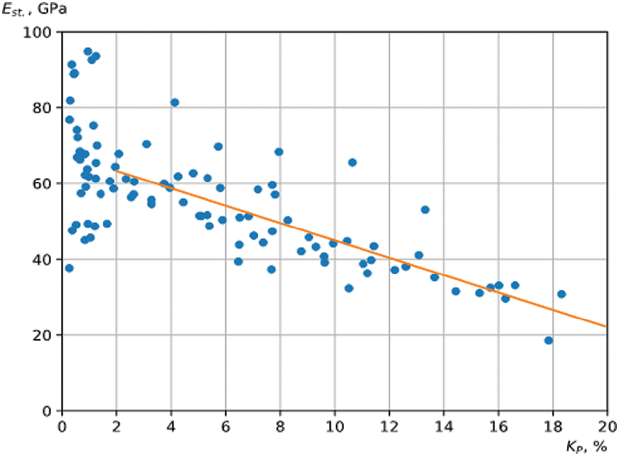
Figure 4: Dependence of the Young’s static modulus on porosity
The absence of interdependence of the values of the considered indicators is established in the region with low porosity (Кр < 2%). In this case, the properties of the minerals composing the skeleton of the rock, and not the size of the void space, become decisive for the elastic ones. But a high convergence of porosity and elasticity parameters was established for more porous rocks (Кр > 2%). The following linear dependence is obtained for this region:
The Young’s moduli are determined for lithotypes of carbonate Verey rocks (see Table 2) according to dependence (3). Since dependence (3) is not informative in the region of Kp < 2%, for rocks with low porosity the Est values are determined depending on the velocity of the longitudinal wave υр according to full-wave acoustic logging.
The following dependence is used for low-pored limestone of Bashkir age:
[25]
The data on a significant change in the properties of mudstone with an increase in stress loads are presented in [26,27]. The elastic-mechanical properties of mudstone are determined with this in mind according to the next dependence:
[24]
The calculation of the minimum horizontal stresses is carried out according to the Eaton formula [28]:
[28]
where σV is the vertical rock pressure, MPa;
α is the Biot coefficient;
Pf is the reservoir pressure, MPa;
Δσh is the tectonic component of mountain pressure, MPa.
Vertical rock pressure is calculated based on the density of rocks determined by the data of density gamma-gamma logging. The translation of the dynamic Poisson’s ratio (
where the indexes “st” and “d” denote a static and dynamic parameter, respectively.
The Bio coefficient (α) and the tectonic component of the rock pressure (Δσh) are determined by formulas (8) and (9):
[28]
where υр is the velocity of the longitudinal wave, m/s, H is the vertical depth of the rocks, m.
As a result, taking into account the geomechanical and technological indicators justified above, the “FracPro 2019” software package for standard and lithotype models is used to simulate the development of a hydraulic fracturing crack. The results show a significant difference in the shape of cracks for standard and lithotype models (Fig. 5).
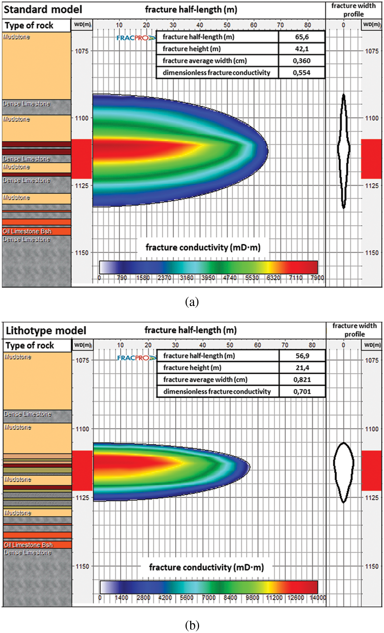
Figure 5: Hydraulic fracturing crack profiles for standard model (a) and lithotype model (b)
The average width of crack development for the lithotype model is 2.3 times higher and is 0.821 cm vs. 0.360 cm in the standard model. The coverage of crack development in height for the lithotype model (21.4 m) is almost 2 times less than that for the standard model (42.1 m). The estimated fracture half-length for the lithotype model is 56.9 m, which is 13.3% less than for the standard model. A significant change in the type of crack development during modeling is most likely due to a decrease in the values of the Young’s modulus and crack toughness for oil-saturated volumes of lithotypes 1, 2 and 3 for the lithotype model.
As a result of calculations, a higher dimensionless fracture conductivity is established for the lithotype model equal to 0.701, which is 1.3 times more than that for the standard model (0.554). This fact indicates increased flow of the rupture fluid due to the assumed greater permeability of the reservoir in the lithotype model.
The X-ray tomography method was used for the first time for the study area to dissect the Verey carbonate strata into various lithological types. Determination of flow and geomechanical characteristics for all lithotypes made it possible to model the crack development process more reliably during mathematical modeling and to obtain a fundamentally different crack geometry (fracture half-length, fracture height and fracture width).
The isolation of lithotypes for carbonate rocks in the geological section, taking into account the differences in their flow and elastic-mechanical parameters, significantly increased the reliability of the lithotype model. The simulation results show that the hydraulic fracturing crack, taking into account the features of the lithotypes of rocks, develops to a lesser extent in height and to a direction away from the well.
An important conclusion is that for the developed lithotype model, unlike the standard model, the hydraulic fracturing crack does not capture the underlying Bashkir formation which may significantly complicate the procedures for the rational development of the Verey reservoir.
The proposed approach allows to increase the reliability of hydraulic fracturing crack modeling and the quality of design of proppant hydraulic fracturing for the territory of investigation in general.
Acknowledgement: The work was carried out on the equipment of The Center for Collective Use «Center for Reservoir Properties of Rocks» as well as using a unique scientific installation «Complex for Studying the Structure of Capacitive Space of Rocks».
Funding Statement: The research was carried out within the framework of the grant for state support of leading scientific schools of the Russian Federation (Grant No. NSh-1010.2022.1.5).
Conflicts of Interest: The authors declare that they have no conflicts of interest to report regarding the present study.
References
1. Novikov, V. A. (2021). Method for forecasting the efficiency of matrix acid treatment of carbonate. Perm Journal of Petroleum and Mining Engineering, 21(3), 137–143. DOI 10.15593/2712-8008/2021.3.6. [Google Scholar] [CrossRef]
2. Martyushev, D. A., Govindarajan, S. K., Li, Y., Yang, Y. (2022). Experimental study of the influence of the content of calcite and dolomite in the rock on the efficiency of acid treatment. Journal of Petroleum Science and Engineering, 208, 109770. DOI 10.1016/j.petrol.2021.109770. [Google Scholar] [CrossRef]
3. Khuzin, R. A., Khizhniak, G. P. (2019). Laboratory research of acid concentration and injection rate on wormholing process under reservoir conditions. Perm Journal of Petroleum and Mining Engineering, 19(4), 356–372. [Google Scholar]
4. Chi, H., Li, G., Huang, Z., Tian, S., Song, X. (2015). Maximum drillable length of the radial horizontal micro-hole drilled with multiple high-pressure water jets. Journal of Natural Gas Science and Engineering, 26, 1042–1049. DOI 10.1016/j.jngse.2015.07.044. [Google Scholar] [CrossRef]
5. Galkin, S. V., Kochnev, A. A., Zotikov, V. I. (2019). Estimate of radial drilling technology efficiency for the bashkir operational oilfields objects of Perm Krai. Journal of Mining Institute, 238, 410–414. DOI 10.31897/pmi.2019.4.410. [Google Scholar] [CrossRef]
6. Bessmertnykh, A., Ballarini, R., Dontsov, E. (2020). The effects of proppant on the near-front behavior of a hydraulic fracture. Engineering Fracture Mechanics, 235, 107110. DOI 10.1016/j.engfracmech.2020.107110. [Google Scholar] [CrossRef]
7. Feng, Y. C., Ma, C. Y., Deng, J. G., Chu, M. M., Hui, C. et al. (2021). A comprehensive review of ultralow-weight proppant technology. Petroleum Science, 18, 807–826. DOI 10.1007/s12182-021-00559-w. [Google Scholar] [CrossRef]
8. Bandara, K. M. A. S., Ranjith, P. G., Rathnaweera, T. D. (2020). Extensive analysis of single ceramic proppant fracture mechanism and the influence of realistic extreme reservoir conditions on proppant mechanical performance. Journal of Petroleum Science and Engineering, 195, 107586. DOI 10.1016/j.petrol.2020.107586. [Google Scholar] [CrossRef]
9. Shapiro, S., Dinske, C. (2021). Stress drop, seismogenic index and fault cohesion of fluid-induced earthquakes. Rock Mechanics and Rock Engineering, 54(10), 5483–5492. DOI 10.1007/s00603-021-02420-3. [Google Scholar] [CrossRef]
10. Dyskin, A., Pasternak, E., Shapiro, S. (2020). Fracture mechanics approach to the problem of subsidence induced by resource extraction. Engineering Fracture Mechanics, 236, 107173. DOI 10.1016/j.engfracmech.2020.107173. [Google Scholar] [CrossRef]
11. Boitz, N., Shapiro, S. (2021). Stress field rotations at the tip of hydraulic fractures: An explanation for half-moon events? 82nd EAGE Conference and Exhibition, vol. 3, pp. 1627–1631. Amsterdam, Netherlands. [Google Scholar]
12. Muther, T., Nizamani, A. A., Ismail, A. R. (2020). Analysis on the effect of different fracture geometries on the productivity of tight gas reservoirs. Malaysian Journal of Fundamental and Applied Sciences, 16(2), 201–211. DOI 10.11113/mjfas.v16n2.1343. [Google Scholar] [CrossRef]
13. Li, H., Shi, Y. (2021). Triaxial experimental investigation into the characteristics of acid-etched fractures and acid fracturing. Journal of Petroleum Science and Engineering, 202, 108431. DOI 10.1016/j.petrol.2021.108431. [Google Scholar] [CrossRef]
14. Syed, F. I., Muther, T., Neghabhan, S., Dahaghi, A. K. (2022). Numerical trend analysis for factors affecting EOR performance and CO2 storage in tight oil reservoirs. Fuel, 316, 123370. DOI 10.1016/j.fuel.2022.123370. [Google Scholar] [CrossRef]
15. Syed, F. I., Muther, T., Dahaghi, A. K., Neghabhan, S. (2022). CO2 EOR performance evaluation in an unconventional reservoir through mechanistic constrained proxy modeling. Fuel, 310, 122390. DOI 10.1016/j.fuel.2021.122390. [Google Scholar] [CrossRef]
16. Galkin, S. V., Savitckii, I. V., Kolychev, I. J., Votinov, A. S. (2021). Prospects for the application of proppant hydraulic fracturing at Kashiro-Verey operational facilities Volga-Ural oil and gas province. SOCAR Proceedings, 2, 257–265. DOI 10.5510/OGP2021SI200605. [Google Scholar] [CrossRef]
17. Raspopov, A. V., Kondratiev, S. A., Sharafeev, R. R., Novokreschennykh, D. V., Drozdov, S. A. (2019). Experience of hydraulic fracturing in oil fields of the Perm region, the Komi Republic and the Nenets autonomous district. Oil Industry, 8, 48–51. DOI 10.24887/0028-2448. [Google Scholar] [CrossRef]
18. Schmitt, M., Halisch, M., Müller, C., Fernandes, C. P. (2016). Classification and quantification of pore shapes in sandstone reservoir rocks. Solid Earth, 7, 285–300. DOI 10.5194/se-7-285-2016. [Google Scholar] [CrossRef]
19. Yang, S. Q., Yang, Z., Jing, H. W., Xu, T. (2020). Fracture evolution mechanism of hollow sandstone under conventional triaxial compression by X-ray micro-CT observations and three-dimensional numerical simulations. International Journal of Solids and Structures, 190, 156–180. DOI 10.1016/j.ijsolstr.2019.11.011. [Google Scholar] [CrossRef]
20. Efimov, A. A., Galkin, S. V., Savitckii, I. V., Galkin, V. I. (2015). Estimation of heterogeneity of oil & gas field carbonate reservoirs by means of computer simulation of core X-ray tomography data. Ecology, Environment and Conservation, 21, 79–85. [Google Scholar]
21. Kantzas, A., Marentette, D. F., Jha, K. N. (1992). Computer-assisted tomography-from qualitative visualization to quantitative core analysis. Journal of Canadian Petroleum Technology, 31(9), 48–56. DOI 10.2118/92-09-06. [Google Scholar] [CrossRef]
22. Cherepanov, S. S., Ponomareva, I. N., Erofeev, A. A., Galkin, S. V. (2014). Determination of fractured rock parameters based on a comprehensive analysis of the data core studies, hydrodynamic and geophysical well tests. Oil Industry, 2, 94–96. [Google Scholar]
23. Zhao, K., Jiang, P., Feng, Y., Sun, X., Cheng, L. et al. (2020). Numerical investigation of hydraulic fracture propagation in naturally fractured reservoirs based on lattice spring model. Geofluids, 2020, 8845990. DOI 10.1155/2020/8845990. [Google Scholar] [CrossRef]
24. Martyushev, D. A., Yurikov, A. (2021). Evaluation of opening of fractures in the Logovskoye carbonate reservoir, Perm Krai, Russia. Petroleum Research, 6(2), 137–143. DOI 10.1016/j.ptlrs.2020.11.002. [Google Scholar] [CrossRef]
25. Kashnikov, Y. A., Ashihmin, S. G. (2019). Rock mechanics in petroleum industry. Moscow: Publishing House “Gornaya Kniga”. [Google Scholar]
26. Seredin, V. V., Galkin, V. I., Rastegaev, A. V., Isaeva, G. A., Parshina, T. Y. (2018). Changes of energy potential on clay particle surfaces at high pressures. Applied Clay Science, 155, 8–14. DOI 10.1016/j.clay.2017.12.042. [Google Scholar] [CrossRef]
27. Seredin, V. V., Andrianov, A. V., Gaynanov, S. K., Galkin, V. I., Andreyko, S. S. (2021). Formation of the kaolin structure treated by pressure. Perm Journal of Petroleum and Mining Engineering, 21(1), 9–16. [Google Scholar]
28. Zoback, M. (2007). Reservoir geomechanics. New York: Cambridge University Press. [Google Scholar]
29. Kondratiev, S. A., Zhukovsky, A. A., Yakimova, T. S., Zhigalov, V. A., Malysheva, V. L. (2017). Prediction of formations stress-state based on special field research and the operations of formation hydraulic fracturing in conditions of the terrigenous reservoirs of Perm region deposits. Geology, Geophysics and Development of Oil and Gas Fields, 12, 58–63. [Google Scholar]
Cite This Article
 Copyright © 2023 The Author(s). Published by Tech Science Press.
This work is licensed under a Creative Commons Attribution 4.0 International License , which permits unrestricted use, distribution, and reproduction in any medium, provided the original work is properly cited.
 Downloads
 Citation Tools