
 Submit a Paper
 Propose a Special lssue
 Open Access
ARTICLE
Analysis of the Microstructure of a Failed Cement Sheath Subjected to Complex Temperature and Pressure Conditions
1 China University of Petroleum, Beijing, 102249, China
2 CNOOC Research Institute, Beijing, 100027, China
3Zhanjiang Branch, CNOOC Energy Technology & Services Limited, Zhanjiang, 524057, China
4 Yangtze University, Wuhan, 430100, China
* Corresponding Author: Qiao Deng. Email:
(This article belongs to the Special Issue: Meshless, Mesh-Based and Mesh-Reduction Methods Based Analysis of Fluid Flow in Porous Media)
Fluid Dynamics & Materials Processing 2023, 19(2), 399-406. https://doi.org/10.32604/fdmp.2022.020402
Received 24 November 2021; Accepted 08 February 2022; Issue published 29 August 2022
 View Full Text
 Download PDF
Abstract
One of the main obstacles hindering the exploitation of high-temperature and high-pressure oil and gas is the sealing integrity of the cement sheath. Analyzing the microstructure of the cement sheath is therefore an important task. In this study, the microstructure of the cement sheath is determined using a CT scanner under different temperature and pressure conditions. The results suggest that the major cause of micro-cracks in the cement is the increase in the casing pressure. When the micro-cracks accumulate to a certain extent, the overall structure of the cement sheath is weakened, resulting in gas channeling, which poses a direct threat to the safe production of oil and gas. A change in the casing temperature has a limited effect on the microstructure of the cement sheath.Keywords
With the increase in offshore oil and gas exploration and development, more and more high-temperature and high-pressure wells have been drilled. However, due to extreme operating conditions, such as ultra-high formation pressure and temperature, the completion of offshore wells is fraught with challenges. Some traditional completion technologies are unable to fulfill the demands of offshore well operating conditions, and one of the major technical challenges is ensuring the sealing integrity of cement sheath in the wells [1]. Cement sheath can provide safe offshore oil and gas production by sealing the reservoir. The mechanical characteristics of cement sheath are crucial since they are directly related to the quality of well completion [2]. Because of the complex operating circumstance, the integrity of cement sheath in deep-water wells is difficult to ensure. The microstructure change of cement sheath subjected to high temperature and high pressure have a significant impact on the sealing integrity of cement sheath. Currently, there is an inadequate study on this subject, thus it is necessary to investigate the change mechanism of microstructure cement sheath subjected to complex temperature and pressure conditions [3].
The most prevalent internal failure mechanism for oil pipelines is corrosion, which comprises pitting corrosion, crevice corrosion, and stress corrosion. The failure process of the system can be divided into two stages: damaged stage, and then failure stage. The chemical reaction process of cement corrosion by CO2 was studied to determine the microstructure, compressive strength, and permeability of corroded cement stone, which revealed that CO2 can react with cement hydration products to form CaCO3 with different crystal structures, destroying the original hydration products and microstructure of cement stone, resulting in decreased compressive strength and increased permeability of corroded cement stone. As temperature and CO2 partial pressure rise, the compressive strength of corroded cement stone falls while the permeability rises [4]. By introducing the notion of the weak interface of cement surface, three types of weak interface microstructure models have been established. The products and morphology of the weak interface, as well as the impact of the weak interface on microstructure, acoustic echo, and interfacial shear strength, have all been characterized, which demonstrates that the weaker the microstructure of the weak interface, the worse the acoustic detection results and the lower the interface shear strength [5]. Electrochemical test, SEM (Scanning Electron Microscope), and energy spectrum analysis was used to investigate the electrochemical, microstructure, and element distribution characteristics of corroded cement sheath, which has practical implications for well completion of acid gas fields containing H2S and CO2 [6]. The key reasons for the weak interface are internal cement factors and the external environment factors according to the analysis of the deterioration mechanism and improvement technique of the weak interface of adjustment well completion. Furthermore, the deterioration mechanism of the weak interface is a more scientific and rational method to evaluate well completion, providing a more targeted and practical approach to investigate the improvement strategies [7]. To analyze the failure mechanisms of the cement sheath of a gas injector, a laboratory experiment was conducted in which the cement sheath was subjected to certain internal circulation pressure, according to the work conditions of the cement sheath in the upper part of the annular space B of gas storage. The sealing integrity, permeability as well as SEM and CT (Computed Tomography) techniques are employed to analyze the change of micro-cracks and pores cement sheath [8].
The aforementioned research focuses on the failure mechanism of cement sheath from a micro perspective. However, the process of the microstructure change of cement sheath under high temperature and high pressure is not well understood. In this paper, the cement sheaths are prepared using a high-temperature and high-pressure cement formula in the self-designed evaluation device for cement sheath sealing integrity under high-temperature and high-pressure conditions. Following that, the prepared cement sheath is scanned by a CT scanner to determine the microstructure change of the cement sheath interface and body. By gathering and analyzing the experimental data, the change mechanism under different temperatures and pressures, as well as the impact of microstructure change cement sheath on the sealing integrity can be further introduced.
In the experiment, the self-designed evaluation device for cement sheath sealing integrity and CT scanner is the key equipment, with the high-speed mixer serving as auxiliary equipment.
To simulate the high-temperature and high-pressure conditions in realistic working, a small-size casing-cement sheath-casing combination evaluation device is designed, as illustrated in Fig. 1. According to the similarity principle, the inner casing diameter of the evaluation device is 35 mm, the wall thickness is 6 mm, the outer casing diameter is 50 mm, and the wall thickness is 3 mm. The plugs seal the upper and lower ends of the combination are sealed using the plugs and set with a pressure differential between 0.01 MPa and 0.05 MPa. High temperature can damage cement sheath, resulting in gas channeling, and that gas channeling can be simulated by this device. The evaluation device for cement sheath sealing integrity can regulate internal casing temperature and pressure. The device can sustain a 0–10 MPa cement slurry annulus pressure and a 0–10 MPa annular gas channeling pressure, the casing can sustain a 0–35 MPa pressure and a 0–180°C temperature. The gas source is N2.
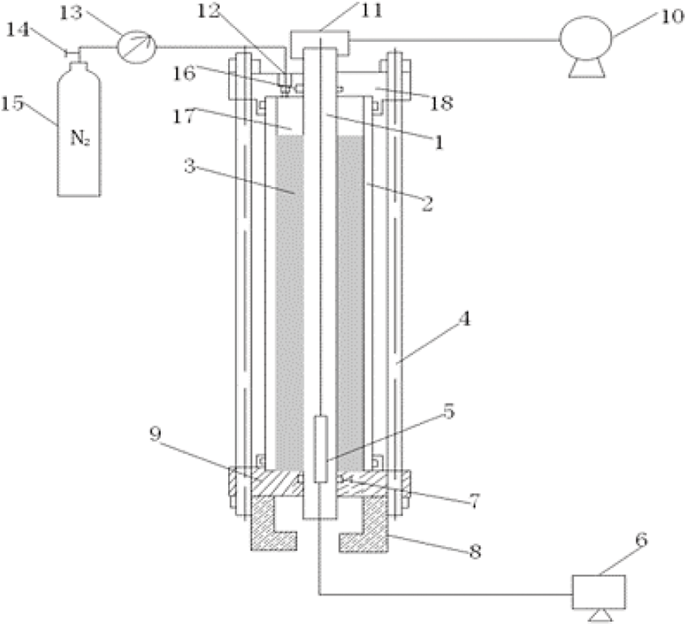
Figure 1: Schematic diagram of small-size evaluation device for cement sheath sealing integrity (1-inner casing; 2-outer casing; 3-cement sheath; 4-high strength tie rod; 5-heating rod; 6-temperature control system; 7-sealing ring; 8-foundation; 9-lower flange; 10-booster pump; 11-upper inlet hole; 12-air inlet; 13-pressure gauge; 14-pressure relief valve; 15-nitrogen cylinder); 16-sealing ring; 17-the oil layer above the cement slurry (Pressurized to prevent boiling of high temperature cement paste); 18-upper flange
The CT scanner is used for determined the microstructure to analyze the damage of cement sheath. However, the CT scanner is limited to steel materials, and cannot penetrate the casing to determine the internal microstructure of the cement sheath. Therefore, a thermoplastic tube, which has the same roughness and size as the casing, is linked to the inner wall of the casing. The cement sheath in the casing can be easily removed and scanned.
Based on this device, it is possible to investigate the effect of cement slurry’s curing temperature, curing duration, temperature change, and casing pressure change on the cementing strength of the first interface, as well as the hydraulic bonding strength of cement sheath under high-temperature and high-pressure conditions. In combination with the CT scanner, the microstructure change of cement sheath can be observed.
Under high-temperature and high-pressure conditions, the cement sheath is fragile, which can easily result in gas channeling, while the microscopic morphology of the cement sheath is unclear [9–24]. To explore the microstructure change mechanism and its influence on the sealing failure of cement sheath, the experimental simulations of cement sheath in the annulus of the vertical well section are performed under different temperatures and pressures. Cement sheath curing temperatures are 50°C, 90°C, 130°C, 150°C, and 180°C, respectively, with 2 MPa annular pressure, 0–5 MPa casing pressure, and 7-day curing duration. The nitrogen cylinder applies pressure to the annulus during the experiment, and the circulation pressure in the casing is obtained by injecting and pushing heat transfer oil using the hand pump.
The cement sheath samples are created using the high-temperature and high-pressure cement formula. The following is the formula for cement composition: water, +100% G-grade cement, +50% heat stabilizer, +5% self-repairing material, +2% anti-channeling enhancer, +1% latex defoamer, +3.5% water-loss reducer, +8% latex, +1% dispersant, +1.5% high temperature retarder, and +0.5% medium temperature retarder. Five groups of cement stones are cured at 50°C, 90°C, 130°C, 150°C, and 180°C, respectively. One of the experimental cement sheath samples is shown in Fig. 2.
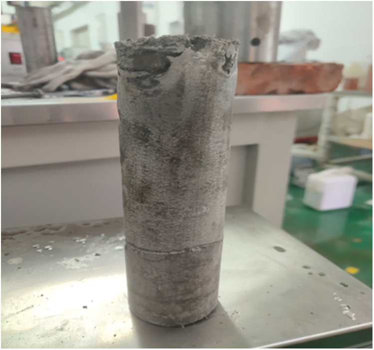
Figure 2: Experimental sample of the cement sheath
(1) In the curing apparatus, the inner wall of the outer casing is covered with an even layer of lubricant and is affixed with a thermoplastic tube heated with hot water. The evaluation device for cement sheath sealing integrity is assembled in order, with the heating rod and temperature sensor connected to the base, as shown in Fig. 3.
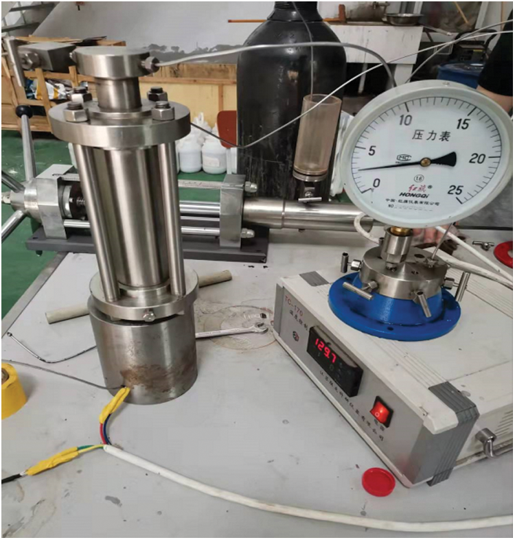
Figure 3: Evaluation device for cement sheath sealing integrity
(2) With the equipment sealed, the prepared cement slurry is injected into the annulus between two simulated casings. The pressure relief valve on the nitrogen cylinder is turned on. By manipulating the two valves, 2 MPa annulus pressure is applied.
(3) The inlet and outlet knob of the hand pump are turned off and the pressure from the casing is pumped into the evaluation device for cement sheath sealing integrity. The cup draws the heat transfer oil into the hand pump. With the inlet knob on, the heat transfer oil in the cup is drawn into the pump by rotating the hand pump knob outward. The outlet knob of the hand pump is turned on, while the pressure knob of the casing into the evaluation device is turned off. The heat transfer oil can be pumped into the small size device, and the pressure gauge can be monitored during operation. The foregoing procedure is repeated until the pressure gauge reaches a certain degree, at which point pressure can be relieved within the range of 0–2.5 MPa by opening the pressure relief valve.
(4) The heating rod and temperature sensor is turned on, and then the cement sheath is cured at a set temperature and pressure for 7 days. After curing, the cement sheath is taken out and scanned by the CT scanner, as shown in Fig. 4.
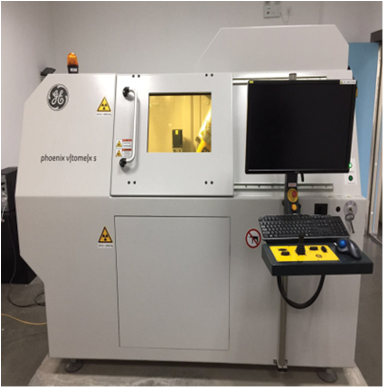
Figure 4: CT scanner
(5) The detection results are determined and analyzed. Several cement sheaths are cured under different temperatures and pressures. The microstructure of the cement sheaths is determined with a CT scanner, and the microstructure change process could be observed.
Based on the preceding experimental steps, the indoor experimental analysis of the microstructure change of cementing cement sheath under different temperatures and pressures is accomplished. Using the cement sheath cured in high-temperature and high-pressure conditions, a microstructure experimental test can be carried out, and the casing pressure is raised by 10 MPa, 20 MPa, and 30 MPa, respectively. The CT scanning results are shown in Fig. 5.
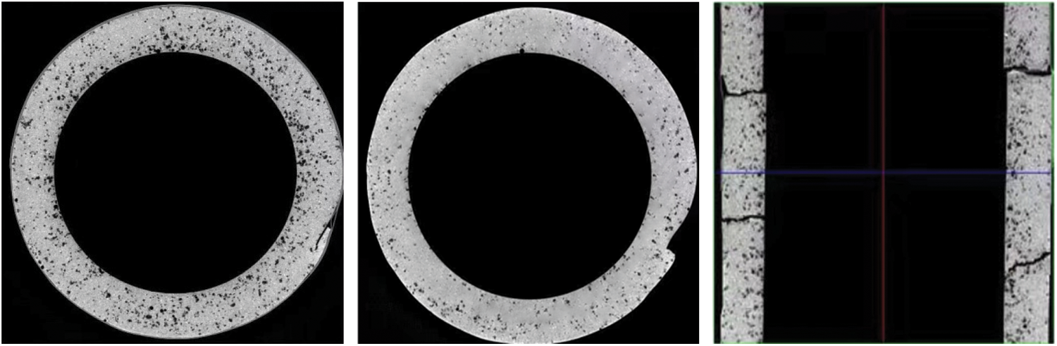
Figure 5: The microstructure change by CT scanning results with a different casing pressure
The black dots in the figures represent the pores identified by CT microscopic scanning. The detection results reveal that the pore distribution is uniform when cement sheath is cured at high temperatures and high pressures. When casing pressure rises to 10 MPa, the pore near the inner casing wall becomes dense, causing internal micro-cracks of the cement sheath. When casing pressure rises to 30 MPa, the internal structure of the cement sheath is damaged, resulting in the sealing failure of the cement sheath.
Fig. 6 shows the CT detection results after changing the temperature in the casing is changed by 20°C, 40°C, and 60°C, respectively, which reveal that increasing the temperature in the casing has little effect on the pore structure, and the pores are evenly distributed across the cement sheath. When the temperature rises to a certain degree, micro-cracks appear inside the cement sheath.
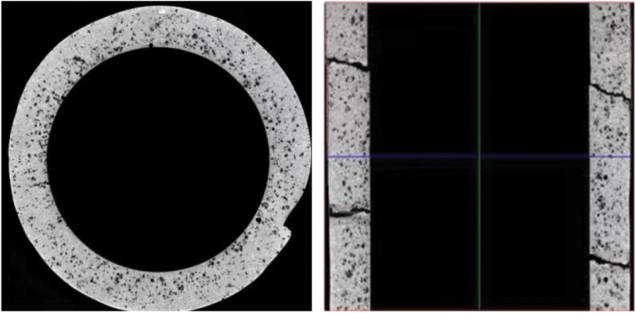
Figure 6: The microstructure change by CT scanning results with different casing temperature
Fig. 7 shows the three-dimensional geometrical model of the cement sheath sample. The model is of the same size and material as the sample in the experiment. The physical model needs to be meshed and divided into hexahedral meshes for numerical simulation, as shown in Fig. 8. The average mesh spacing is about 2.5 mm, and there are about 3000 meshes in total. Based on the numerical simulation model, temperature, pressure, as well as other experiment-relevant condition parameters are set, and the numerical simulation computation is carried out using finite element analysis software [25]. The simulation results reveal that temperature and pressure significantly impact the generation and change of the cement sheath microstructure, which is supported by the experimental results.
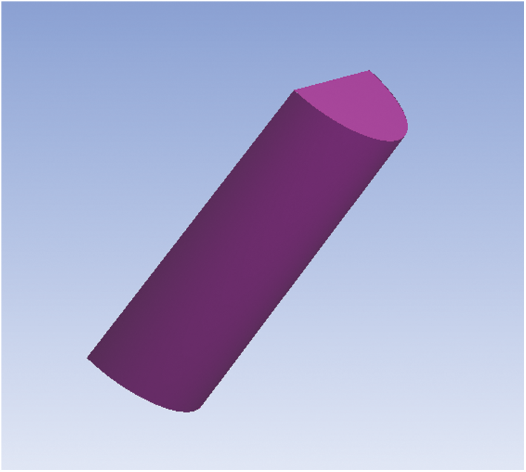
Figure 7: Half of the three-dimensional geometrical model of the cement sheath sample
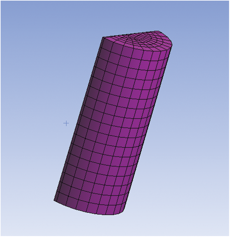
Figure 8: Mesh model of cement sheath sample
(1) The pore distribution of the cement sheath cured under high-temperature and high-pressure conditions is relatively uniform. With the increase of the pressure in the casing, the local compaction micro-cracks of the cement sheath cause a changing process of local compaction, micro-cracks generation, and micro-cracks increase, until the cement sheath structure is damaged, and the sealing integrity fails.
(2) Initially, with the casing temperature rising, the internal structure of the cement sheath does not change significantly. When the temperature rises to a certain degree, the micro-cracks appear inside the cement sheath, and the micro-cracks do not significantly increase with the temperature rising.
(3) The failure mechanism of cement sealing integrity is different due to different temperatures and pressures. A suitable cement formula needs to be chosen according to the actual conditions of the oil and gas well.
Acknowledgement: The authors gratefully acknowledge the research project from “Study of Risk assessment and Countermeasures of Well Drilling and Completion under Ultra-High Temperature and High Pressure” and “Research on Development Feasibility of LS25-1 Gas Field” (Grant Nos. YXKY-ZX-09-2021, 2020FS-08).
Funding Statement: The authors received no specific funding for this study.
Conflicts of Interest: The authors declare that they have no conflicts of interest to report regarding the present study.
References
1. Li, Z., Xie, R. J., Wu, Y., Yuan, J. L. (2021). Progress and prospect of CNOOC’s oil and gas well drilling and completion technologies. Natural Gas Industry, 41(8), 178–185. DOI 10.3787/j.issn.1000-0976.2021.08.016. [Google Scholar] [CrossRef]
2. Liu, W. D., Zhu, X. H., Jiang, W. H., Fan, P., Wang, Y. H. et al. (2019). Evaluation of shale micro-fracture simulation experiments. Drilling and Production Technology, 42(2), 104–107. DOI 10.3969/j.issn.1006-768X.2019.02.29. [Google Scholar] [CrossRef]
3. Elaheh, A., Terry, B., Nguyen, G. D. (2018). Evaluation of cement sheath integrity subject to enhanced pressure. Journal of Petroleum Science and Engineering, 170, 1–13. DOI 10.1016/j.petrol.2018.06.013. [Google Scholar] [CrossRef]
4. Zhang, J. F., Xu, M., Zhu, J. J. (2007). Corrosion of oilwell cement by carbon dioxide. Journal of the Chinese Ceramic Society, 35(12), 1651–1656. DOI 10.3321/j.issn:0454-5648.2007.12.018. [Google Scholar] [CrossRef]
5. Yang, X. T., Wang, K. C., Zhang, L. (2010). Discussion on the weak interface of adjustment well cementing. Drilling Fluids and Completion Fluids, 27(5), 55–57. DOI 10.3969/j.issn.1001-5620.2010.05.017. [Google Scholar] [CrossRef]
6. Ren, C. Q., Guo, M. L., Cheng, X. W., Wang, X., Guo, X. Y. (2010). Corrosion performance of well cement annulus in formation water of east Sichuan gas field. Journal of Southwest Petroleum University (Science & Technology Edition), 32(4), 167–170. DOI 10.3863/j.issn.1674-5086.2010.04.032. [Google Scholar] [CrossRef]
7. Yang, Z. G., Yang, X. T., Zhang, L. (2010). Deterioration mechanism of cementing weak interface and improvement methods. Drilling Fluids and Completion Fluids, 37(3), 79–83, 101. DOI 10.3969/j.issn.1001-5620.2010.03.022. [Google Scholar]
8. Shu, G., Liu, J., Feng, F. (2020). Experimental study on failure mechanism of cement sheath in injection and production wells of gas storage. Drilling Fluids and Completion Fluids, 37(4), 507–511+520. DOI 10.3969/j.issn.1001-5620.2020.04.017. [Google Scholar] [CrossRef]
9. Carter, L., Evans, G. (1964). A study of cement-pipe bonding. Journal of Petroleum Technology, 16(2), 157–160. DOI 10.2118/764-PA. [Google Scholar] [CrossRef]
10. Ladva, H. K., Craster, B., Jones, T. G. (2004). The cement-to-formation interface in zonal isolation. SPE Drilling and Completion, 20, 186–197. DOI 10.2118/88016-PA. [Google Scholar] [CrossRef]
11. Gray, K. E., Podnos, E., Becker, E. (2007). Finite element studies of near-wellbore region during cementing operations: Part I. SPE Drilling and Completion, 24(1), 127–136. DOI 10.2118/106998-PA. [Google Scholar] [CrossRef]
12. Zhang, L. Y., Mao, X. B., Lu, A. H. (2010). Experimental study on rock mechanical properties under high temperature. SCIENTIA SINICA Technologica, 40(2), 157–162. DOI 10.1360/ze2010-40-2-157. [Google Scholar] [CrossRef]
13. Yang, Z. J., Zhu, H. T., Wang, J. H. (2012). Self-repair technology for gas channeling in natural gas well suites surgery. Natural Gas Industry, 32(10), 55–58. DOI 10.3787/j.issn.1000-0976.2012.10.013. [Google Scholar] [CrossRef]
14. Lu, Y. F., Zheng, Y. Z., She, C. Y. (2013). Analysis of mechanical integrity of cement ring based on experimental data of cement stone. Natural Gas Industry, 33(5), 77–81. DOI 10.3787/j.issn.1000-0976.2013.05.014. [Google Scholar] [CrossRef]
15. Shadravan, A., Schubert, J., Amani, M. (2015). Using fatigue failure envelope for cement sheath integrity evaluation. SPE Drilling and Completion, 30(1), 68–75. DOI 10.2118/168321-PA. [Google Scholar] [CrossRef]
16. Andrade, J. D., Sangesland, S. (2016). Cement sheath failure mechanisms: Numerical estimates to design for long-term well integrity. Journal of Petroleum Science and Engineering, 147, 682–698. DOI 10.1016/j.petrol.2016.08.032. [Google Scholar] [CrossRef]
17. Gholami, R., Aadnoy, B., Fakhari, N. (2016). A thermo-poroelastic analytical approach to evaluate cement sheath integrity in deep vertical wells. Journal of Petroleum Science and Engineering, 147, 536–546. DOI 10.1016/j.petrol.2016.09.024. [Google Scholar] [CrossRef]
18. Andrade, J. D., Sangesland, S., Skropa, R. (2016). Experimental laboratory setup for visualization and quantification of cement-sheath integrity. SPE Drilling and Completion, 31(4), 317–326. DOI 10.2118/173871-PA. [Google Scholar] [CrossRef]
19. Shen, J. Y., Shi, L., Li, Y. (2017). Analysis and prospect of cement sheath sealing integrity under large differential pressure. Natural Gas Industry, 37(4), 98–108. DOI 10.3787/j.issn.1000-0976.2017.04.012. [Google Scholar] [CrossRef]
20. Teodoriu, C., Bello, O. (2020). A review of cement testing apparatus and methods under CO2 environment and their impact on well integrity prediction—Where do we stand? Journal of Petroleum Science and Engineering, 187(4), 106736. DOI 10.1016/j.petrol.2019.106736. [Google Scholar] [CrossRef]
21. Al Ramis, H., Teodoriu, C., Bello, O., Al Marhoon, Z. (2020). High definition optical method for evaluation of casing—Cement microannulus (CCMA). Journal of Petroleum Science and Engineering, 195, 107719. DOI 10.1016/j.petrol.2020.107719. [Google Scholar] [CrossRef]
22. Qiu, Q., Cui, L. (2018). Reliability evaluation based on a dependent two-stage failure process with competing failures. Applied Mathematical Modelling, 64(2), 699–712. DOI 10.1016/j.apm.2018.07.039. [Google Scholar] [CrossRef]
23. Akinwamide, S. O., Lemika, S. M., Obadele, B. A., Akinribide, O. J., Abe, B. T. (2019). A study on microstructural and mechanical properties of a stir cast Al (SiC-Mg-TiFe) composite. Fluid Dynamics & Materials Processing, 15(1), 15–26. DOI 10.32604/fdmp.2019.04761. [Google Scholar] [CrossRef]
24. Qiu, Q., Cui, L. (2019). Optimal mission abort policy for systems subject to random shocks based on virtual age process. Reliability Engineering & System Safety, 189(4), 11–20. DOI 10.1016/j.ress.2019.04.010. [Google Scholar] [CrossRef]
25. Lee, H. H. (2021). Finite element simulations with ANSYS workbench 2021: Theory, applications, case studies. USA: SDC Publications. [Google Scholar]
Cite This Article
 Copyright © 2023 The Author(s). Published by Tech Science Press.
This work is licensed under a Creative Commons Attribution 4.0 International License , which permits unrestricted use, distribution, and reproduction in any medium, provided the original work is properly cited.
 Downloads
 Citation Tools