
 Submit a Paper
 Propose a Special lssue
 Open Access
ARTICLE
An Integrated Oil Production Enhancement Technology Based on Waterflooding Energy Recovery
1 Perm National Research Polytechnic University, Perm, 614990, Russian
2 Department of Oil Field Development and Operation, Gubkin Russian State University of Oil and Gas, Moscow, 119991, Russia
3 China University of Petroleum (East China), Qingdao, 266000, China
* Corresponding Author: Aleksandr Lekomtsev. Email:
(This article belongs to the Special Issue: Fluid Dynamics & Materials Processing in the Oil and Gas Industry)
Fluid Dynamics & Materials Processing 2023, 19(2), 285-301. https://doi.org/10.32604/fdmp.2022.019809
Received 16 October 2021; Accepted 23 May 2022; Issue published 29 August 2022
 View Full Text
 Download PDF
Abstract
A new integrated oil production enhancement technology based on water-flooding energy recovery is proposed. After providing an extensive review of the existing scientific and technical literature on this subject, the proposed integrated technology is described together with the related process flow diagram, the criteria used to select a target facility for its implementation and the outcomes of the laboratory studies conducted to analyze emulsion formation and separation kinetics. Moreover, the outcomes of numerical simulations performed using Ansys CFX software are also presented. According to these results, using the proposed approach the incremental oil production may reach 1.2 t/day (with a 13% increase) and more, even at low flow rates (less than 10 t/day), thereby providing evidence for the benefits associated with this integrated technology.Keywords
Oil and gas producers are currently focusing on improving oil production efficiency amid the slumping demand for hydrocarbons and relatively low hydrocarbon prices [1–5]. Oil production efficiency relies on several factors, including the operating conditions of producing wells determining the choice of surface and subsurface equipment, its operating parameters, hydrocarbon properties, etc. [6,7]. Ongoing industry trends are focused on improving oil production efficiency without replacing downhole pumping equipment or changing the existing oil gathering, transportation, and treatment system [8–11]. The development of more advanced equipment and technologies sets the stage for enhanced oil recovery without having to refocus production processes by optimising existing equipment operation.
Many technologies known to improve oil production efficiency [12–17] are classified according to the type of problem solved. For example, chemical additives like demulsifiers, corrosion and asphaltene, and resin and paraffin deposition inhibitors are widely used in oil production with high viscosity, high asphaltene, resin and paraffin content, and high corrosiveness [18–20]. The choice of technology depends on the specific conditions of the production of hydrocarbons and their physical and chemical properties. Chemical agents and additives may be used to get rid of a particular complicating factor or several factors simultaneously (combined-effect chemicals). The critical factor contributing to treatment success and efficiency is the choice of chemical [21,22]. The works [23–28] selected a demulsifier grade and determined consumption to inhibit emulsification during water-in-oil emulsion production and transportation, which showed a high degree of breakdown at the in-pipe demulsification stage and during oil treatment.
As previously noted, a high gas content at downhole pumping equipment intake results in a lower oil production efficiency [29–35]. The key methods to combat the harmful effect of gas include lowering submersible equipment below the dynamic fluid level, using special ESP stages designed for efficient operation in gas-saturated media, installing booster devices (gas separators and gas dispersants), and using ESP sections of different sizes, etc. [36–39]. These methods have been proven to have a high practical efficiency [40,41].
Jet pumps are now widely used across the entire oil recovery, gathering, transportation, and treatment chain [42–51]. The key priority in jet pump development lies in design upgrade [52–56]. Much attention in modern research is paid to a thorough study of the flow process in jet pumps [57,58]. In this context, this work focuses on the development and scientific validation of a waterflooding-based integrated enhanced oil recovery technology using a high-pressure ejector to improve oil production efficiency.
2.1 Description of the Integrated Technology
Field waterflooding allows retaining a high energy potential due to the high pressure in the piping system. The authors propose to efficiently use waterflooding system energy as an active medium of the surface jet pump; the passive medium here is the water-in-oil emulsion from the gathering line after the automatic well pad meter station. The proposed technology has several advantages, including less capital expenditures and the ability to use existing well pads and well infrastructure.
The process flow diagram is shown in Fig. 1.
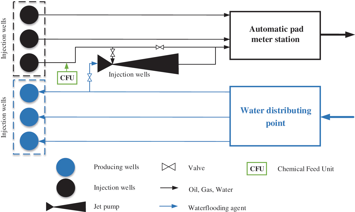
Figure 1: Integrated technology process flow diagram
The technology is implemented as follows: a well pad is equipped with a high-pressure surface ejector, where the active medium is a chemical from the reservoir pressure maintenance system and the passive medium is a gas-liquid mixture from the producing well. A chemical feed unit mounted on the producing well flow line helps avoid the formation of a stable emulsion when implementing the technology due to intensive dispersion and demulsifier stirring in the high-pressure ejector. The described technology will allow reducing the linear pressure of the producing well, which provides conditions for annular pressure decline and an increase in submergence depth of the downhole pumping equipment below the dynamic fluid level. The downhole pumping equipment submergence under dynamic fluid level enhances the reliability of the submersible equipment, reduces failure rates, and drives up well fluid withdrawal.
A technology for annulus gas pump-out using a downhole jet pump [59] already exists. The module includes a pipe string fitted with a jet pump. The lack of anytime personnel access to the module imposes certain technical constraints, complicates operation and process control, and leads to poor maintainability.
2.2 Candidate Well Selection Criteria
A substantiated implementation of the developed enhanced oil recovery technology requires a comprehensive selection of a target for testing the development outcome. The best target is a producing well complying with the following requirements:
– Operated with an electric submersible pump and electric screw pump, i.e., operating without a significant pressure surge;
– Having a high linear and annular pressure;
– Having a high gas/oil ratio (above 25 m3/t);
– In-field pipeline capacity potential at minimum 40% of the existing capacity;
– Well pad located close to a free-water knockout unit or oil pre-treatment unit to avoid additional pumping through booster pump stations.
The essential requirement for operating producing wells with electric screw pumps and submersible pumps is maintaining consistent hydrocarbon recovery, i.e., a constant production rate and pumping head over long-term operation. Complying with this criterion will mitigate the risks associated with the accuracy in the choice and design of the jet pump, as well as boost the designed unit stability. The technology is designed to be implemented at well pads located relatively close to oil treatment gathering stations (oil pre-treatment unit and free-water knockout unit) to eliminate additional fluid transportation and pumping through the gathering and transportation system. The pressure maintenance system situated at the well pad can be implemented using fresh water as a working agent, which will allow additional oil desalting and improve its quality at field treatment. Preliminary calculations of the jet pump operation allowed determining an optimal range of well production water cut for the use of the given technology between 50% and 80%. The specified water cut range was selected to pass to the right-hand side of the emulsion viscosity-water cut dependency, i.e., to provide a water-in-oil emulsion to reduce the viscosity of the transported fluid and intensify system separation kinetics [60].
2.3 Integrated Technology Target Selection
The development of criteria for efficient application of the integrated enhanced production technology based on pressure maintenance system energy recovery allows effectively choosing a target for its introduction and eliminating possible risks of failure to achieve the set objectives.
The objective of the research was determined in compliance with the developed criteria. Producing well with reference #1 was selected. Producing Well #1 is operated with the ESP-25-1500 electric submersible pump unit. The operating parameters are given in Table 1.
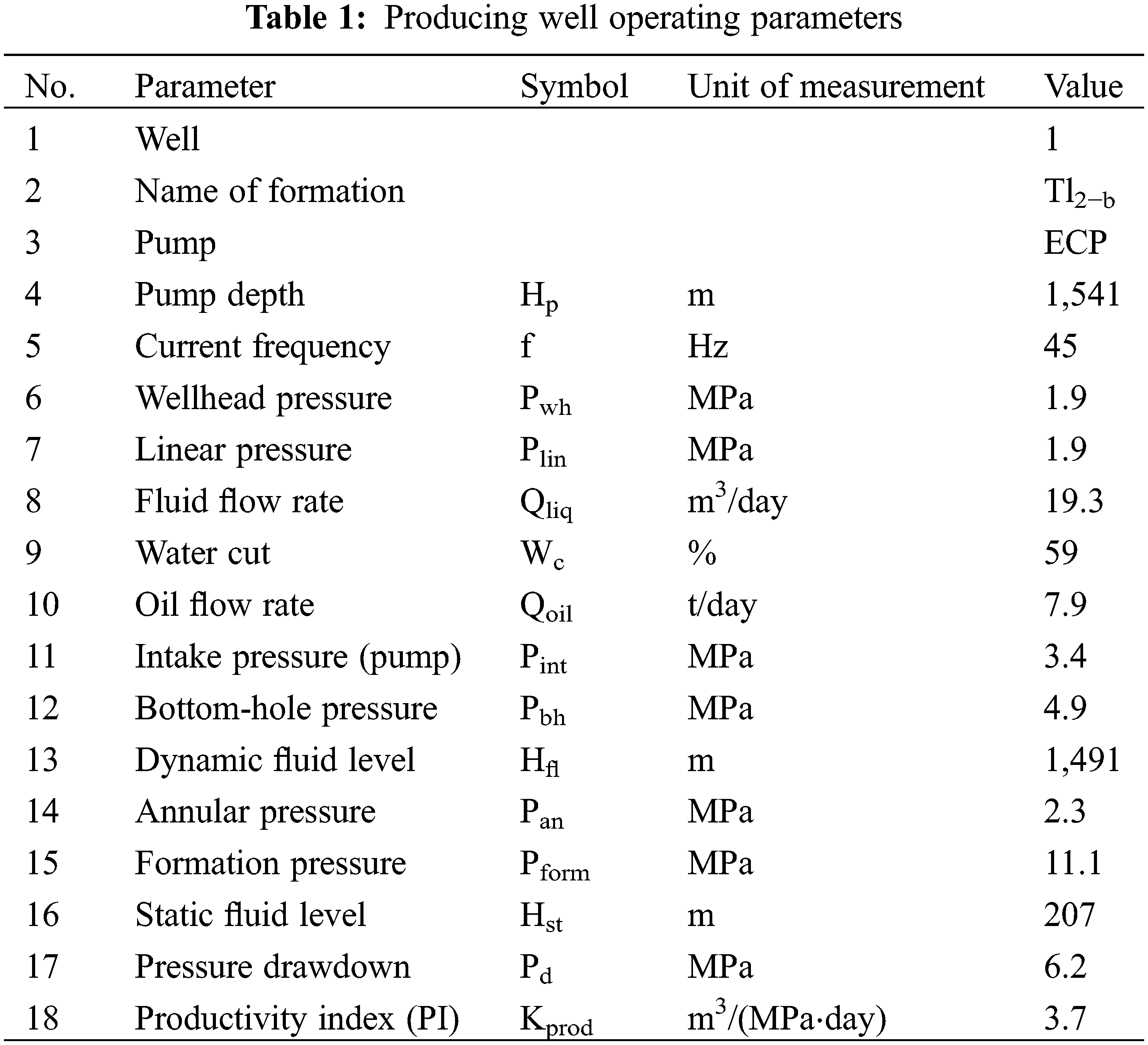
The Table shows that the linear pressure equals the wellhead pressure and is 1.9 MPa. The annular pressure is 2.3 MPa, the intake pressure at the electric submersible pump is 3.4 MPa, the fluid flow rate is 17.9 m3/day, and oil flow rate is 8.9 t/day. Analysis of well operating parameters shows that the submersible pump effective intake pressure (difference between the intake pressure and the annular pressure) is 1.1 MPa, which can lead to pump starvation and therefore cut time between overhaul. The water cut is 59%, which promotes water-in-oil emulsion formation.
2.4 Water-in-Oil Emulsion Properties
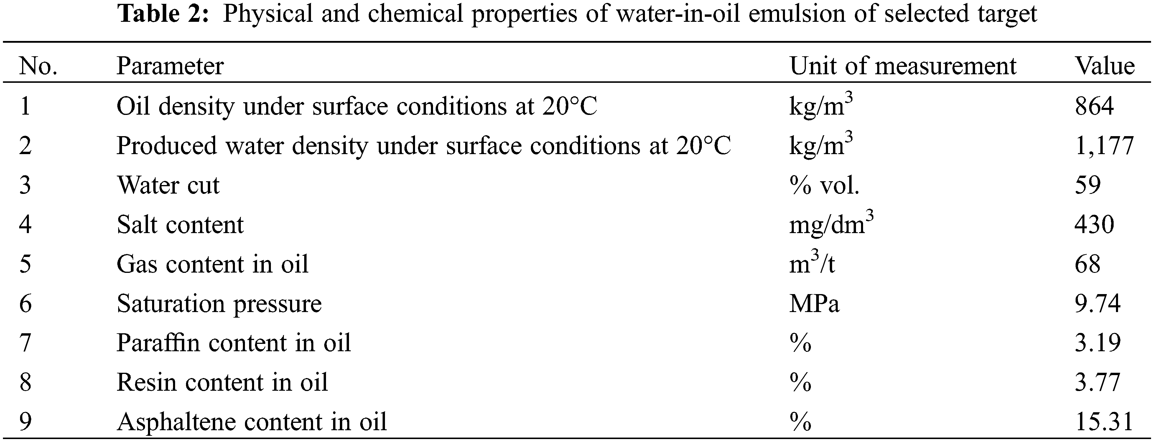
The physical and chemical properties of Well #1’s water-in-oil emulsion are given in Table 2.
2.5 Preparation of Water-in-Oil Emulsion Models
Laboratory experiments were conducted on pre-sampled reservoir fluids of the implementation target. Water-in-oil emulsion models were prepared using a dedicated laboratory stirrer. The linear speed of emulsion stirring in the jet pump contractor was converted to the angular rotation speed of the stirrer using the formulas:
where
The average speed of emulsion flow in the jet pump contractor is 15–20 m/s, which is equal to 2,800–3,800 rpm of the stirrer. All laboratory tests were carried out at an emulsion temperature of 10°С, which corresponds to the average annual temperature of the emulsion in the target technology implementation area.
The intensity of stable water-in-oil emulsions formation of the research target was determined by dispersion analysis by varying the stirrer rpm. The average diameter was determined using a trinocular laboratory microscope. A fragment (up to 1 ml) of the emulsion was withdrawn from the prepared stirred sample for 30–60 s and transferred to a slide.
The water-in-oil emulsion separation kinetics were analysed using the bottle test technique, which essentially consists in determining the volume of the water separated from the water-in-oil emulsion prepared in a stirrer in graduated cylinders over time. The emulsion dehydration degree is defined as the ratio of the free separated water volume to the total volume of water in the sample [61].
2.8 Calculation of oil Production Increase
The oil production increase potential resulting from the annular pressure drop is calculated using the formula [62]:
where
2.9 Jet Pump Mathematical Model
The paper solves the problem of determining the characteristics of multiphase flow: including oil and water, formed in an oil jet pump. Oil and water are considered as continuous fluid, to describe the motion of which the Eulerian approach is used. Both fluids are incompressible. The simulated process is considered isothermal. The steady-state multiphase flow is determined in the research, transients are not considered.
The modeling uses an approach which means that each fluid is possessed its own flow field. The behavior of each fluid is described by its own system of the Navier-Stokes equations. The components of the velocity and pressure vectors are determined in the Navier-Stokes equations while the fluids interact with each other through interfacial forces.
Further, the α phase will mean water, and the β phase–oil, the volume fraction of the phases in the control volume will be denoted as
The mathematical formulation of the problem being solved is written in the form of the following Reynolds Averaged Navier-Stokes equations:
Momentum equations for
where for phase α are denoted
Continuity equations:
Eqs. (4) and (5) for the β phase are written similarly, but the α index changes to β.
Volume conservation equation:
It is assumed that both phases have the same pressure field:
2.9.1 The Mixture Model for the Description Interfacial Transfer of Momentum
For the description inhomogeneous multiphase flow is used a mixture model that treats both phases
where
where
In the applied mixture model, it is assumed that the interfacial forces
The independent variables in Eqs. (4)–(7) are the volume fractions
The eddy viscosity hypothesis is assumed to hold for each turbulent phase. Diffusion of momentum in phase
where
The research uses a k-ε turbulence model (k-ε model) with wall functions:
where
2.9.3 Turbulence Dissipation Rate
The transport equations for k and
where
For the
At the area boundary through which water is supplied to the domain, the bulk mass flow rate is set 1 kg/s, also volume fraction of water and oil
At the area boundary through which oil is supplied to the domain, the bulk mass flow rate is set 0.116 kg/s, also volume fraction of water and oil
A relative pressure of 1.9 MPa is set at the exit from the design area.
At the remaining boundaries of the domain, the conditions for complete adhesion to smooth walls are set.
3.1 Dispersion Analysis Results
The variation of the average diameter of water globules in the simulated emulsion and its specific surface area as a function of rpm is shown in Fig. 2. The tests were carried out using an original emulsion with a water cut of 59%.
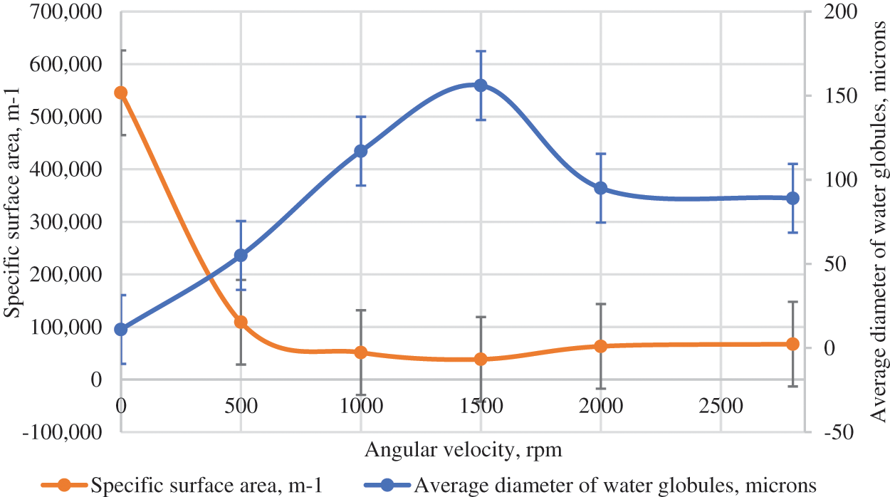
Figure 2: Variation of emulsion dispersion and specific surface area at various stirrer rpm
The diameter of the water globules in the emulsion expands to 156 μm at 1,500 rpm and then gradually decreases to 89 μm as the stirrer speeds up to 2,800 rpm, which indicates an intensification of dispersion processes and an increase in emulsion stability. Fig. 3 shows an example of a processed photomicrograph from the built-in digital camera of the microscope.
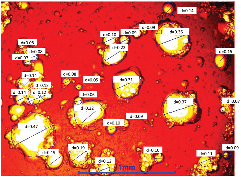
Figure 3: Water-in-oil emulsion photomicrograph taken on a Levenhuk MED D10T microscope at 1,000 rpm and 4× magnification, d, mm
Due to the time available, the sampling technique, and emulsion fragment application onto the slide, the dispersed phase micro-droplets were able to coalesce, as illustrated by the results given in Fig. 3 (values range with stirrer speed up to 1,500 rpm). Emulsion samples to the right of the 1,500 rpm range were more persistent and remained stable for the given time.
3.2 Results of Separation Kinetics
Water-in-oil emulsion separation kinetics at different oil/water volume ratios were analysed using the above bottle test. Fig. 4 shows the change in the emulsion dehydration degree as a function of separation time at different oil/water volume ratios.
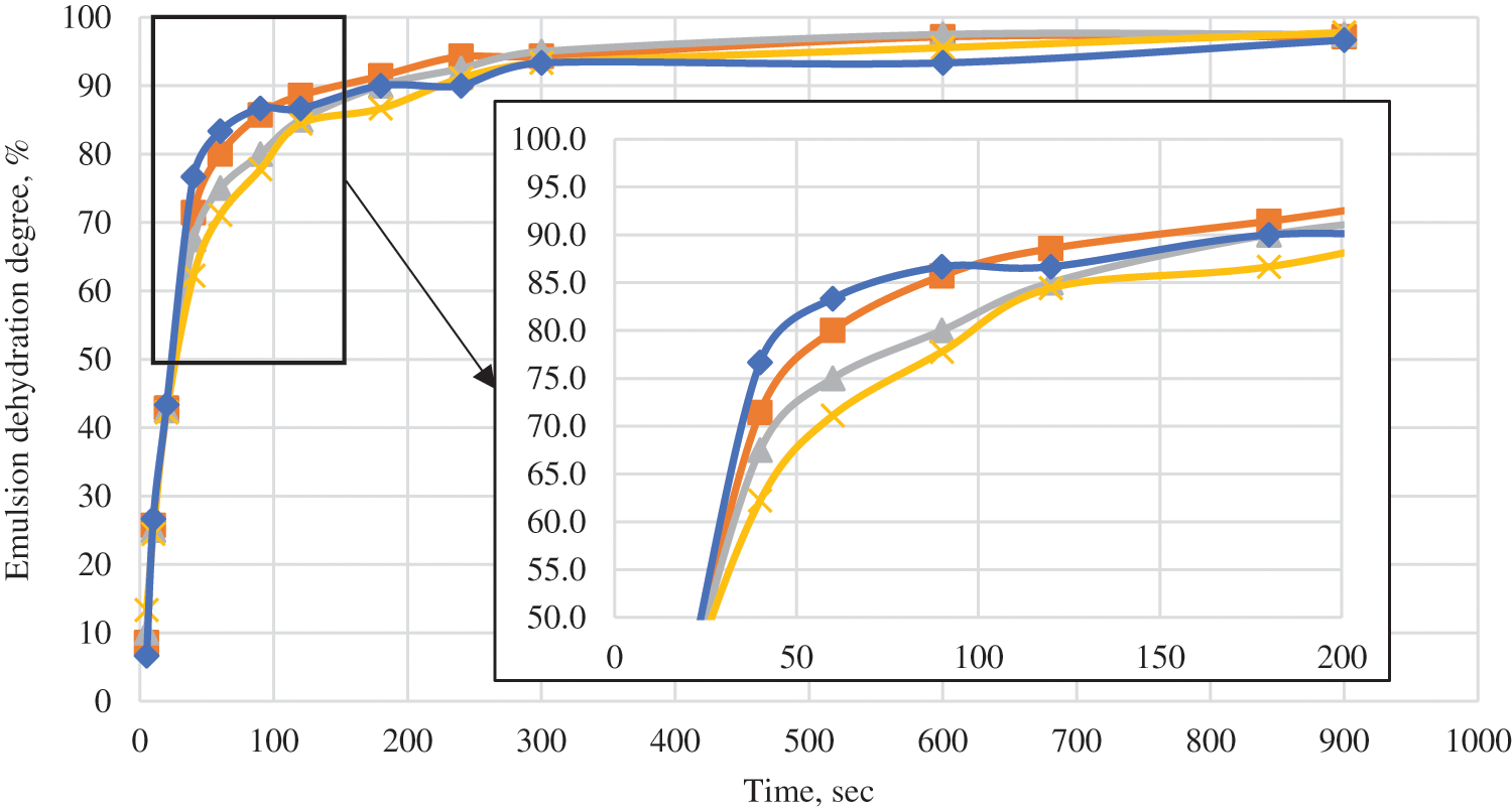
Figure 4: Change in emulsion dehydration degree as a function of separation time at different oil/water volume ratios (
All emulsion types created are susceptible to self-breaking to a dehydration degree of 96–97% within a short period of time (6 min), which signifies the formation of an unstable emulsion when implementing the integrated technology. Thus, the stirring-derived product comprising well crude oil and an additional volume of water from the pressure maintenance system will be subject to natural in-pipe demulsification during transportation across the gathering system.
The authors performed a numerical simulation of the jet pump under given operating conditions using the pro-grade analytical complex Ansys CFX.
The numerical solution of the presented system of differential equations with given boundary conditions is carried out using the well-known finite volume method. A three-dimensional (3D) computational grid consisting of tetrahedral and prismatic elements is created inside the multiphase flow domain under consideration. During the numerical procedure, the characteristics of the multiphase flow, for example, velocity and pressure, are determined in the nodes of the volumetric calculation grid. The change of continuous fields of velocities, pressures, etc., inside the created elements is described by introducing shape functions that are approximations of fields through the desired values in the grid nodes.
In the finite volume method, a control volume is formed for each node from the surrounding parts of the elements. Next, the integration of Eqs. (4) and (5) occurs, while, Gauss’ Divergence Theorem is applied to convert volume integrals involving divergence and gradient operators to surface integrals. The discretization of integrals is carried out numerically using known integration schemes and given integration points. The value of integrand expressions at integration points is determined using approximation by form functions and advection schemes. Central differences scheme, Upwind (first or second order), QUICK, etc., are often used as such schemes. In the calculation algorithm we use, a High resolution scheme was used for the main equations, which is a bound second-order Upwind biased discretization and has a second order of accuracy in the scheme used the blend factor values vary throughout the domain based on the local solution field in order to enforce a boundedness criterion. In flow regions with low variable gradients, the blend factor will be close to 1.0 for accuracy. In areas where the gradients change sharply, the blend factor will be closer to 0.0 to prevent overshoots and undershoots and maintain robustness. For turbulence equations, the first-order Upwind scheme was used.
The Navier-Stokes equations include fluid pressure and velocities, which, in the case of incompressibility of the medium, can be determined by solving separate equations using segregated algorithms with an additional pressure-velocity coupling scheme (well-known numerical procedures as SIMPLE, SIMPLEC, PISO, etc., are used) and by jointly solving all equations simultaneously in a single numerical procedure with a common matrix. In this case, the associated solver is applied. This is the approach used in this study, a pressure-based solver from the ANSYS CFS software is involved.
Numerical procedure uses a co-located (non-staggered) grid layout such that the control volumes are identical for all transport equations. As discussed by Patankar [63], however, naive co-located methods lead to a decoupled (checkerboard) pressure field. Rhie et al. [64] proposed an alternative discretization for the mass flows to avoid the decoupling, and this discretization was modified by Majumdar [65] to remove the dependence of the steady-state solution on the time step. A similar strategy is adopted in this research.
The ANSYS CFX software package uses a coupled solver, which solves the hydrodynamic equations (for u, v, w, p) as a single system. This solution approach uses a fully implicit discretization of the equations at any given step). As a result, the solution of a system of partial differential equations is reduced to finding a solution to a system of algebraic equations. Directly in the problem being solved, the components of the velocity vector for water and oil, pressure, volume fractions of water and oil, parameters k and ε of the turbulence model for the water and oil phases were the unknowns determined in the nodes. Ansys CFX uses a Multigrid accelerated Incomplete Lower Upper factorization technique for solving the discrete system of linearized equations. It is an iterative solver. Ansys CFX uses a particular implementation of Algebraic Multigrid [66] called Additive Correction.
As it is mentioned earlier, the study determines the steady state solution of a multiphase flow, transients are not considered. The corresponding mathematical formulation with defining relations is presented in the form of Eqs. (4)–(15). However, the numerical implementation of the solution of the stationary problem, carried out by the solver of the ANSYS CFX package, is carried out using psuedo-time as a iteration method to converge to the final steady solution. For steady-state problems, the time-step behaves like an ‘acceleration parameter’, to guide the approximate solutions in a physically based manner to a steady-state solution. The pseudo time method option applies an advanced form of implicit under-relaxation that adjusts the relaxation factor dynamically during the simulation according to the flow field behavior. The ANSYS CFX package used automatic time scale calculation, which provided slower but more guaranteed convergence under conservative estimation conditions. Fig. 5 presents four finite meshes and their main parameters used in modelling the ejection process.
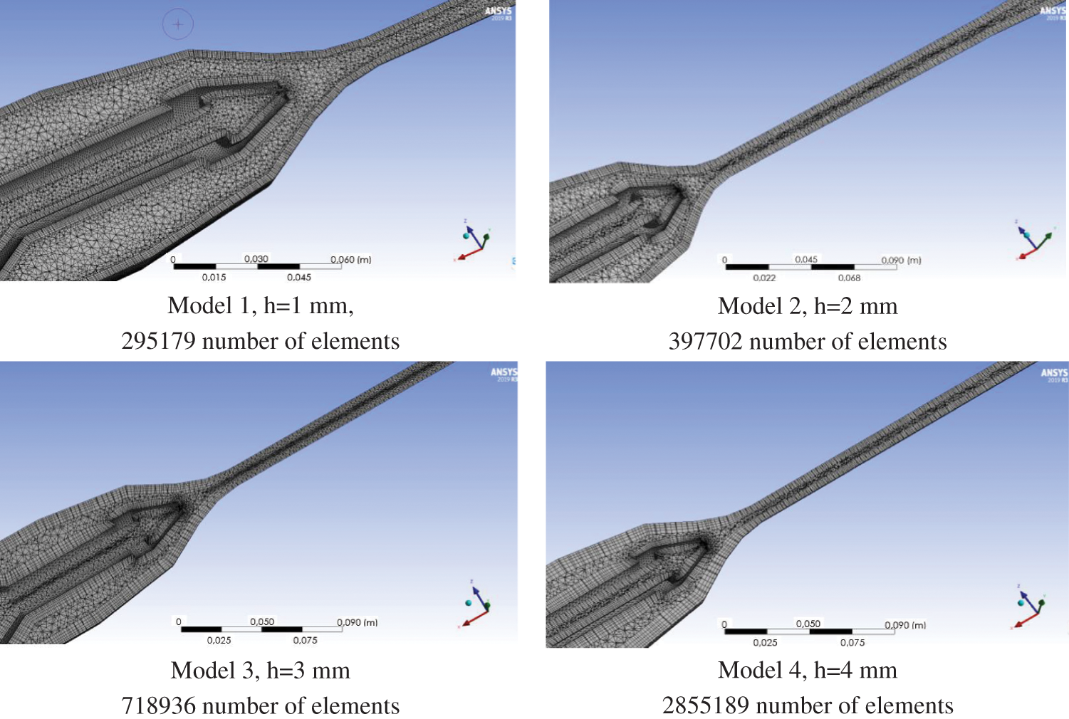
Figure 5: Finite mesh used in modelling the ejection process
Fig. 6 shows the outlet pressure of the jet pump nozzle in relation to the finite mesh size.
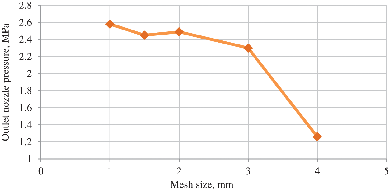
Figure 6: Pressure distribution at outlet of jet pump nozzle in relation to finite mesh size
The mesh size sensitivity of the jet pump model was analyzed by modelling a water-oil mixing problem and through jet pump hydrodynamic tests using a series of models with the same geometry but different structured mesh sizes. The main criteria of the assessment sensitivity of the model and for proving mesh size was the jet pump outlet pressure.
Analysis of the mesh sensitivity shows that the finite mesh size affects the results of the numerical simulation. A mesh size of 2 mm or less does not lead to a change in the final result (linear pressure–as the resulting criterion in numerical simulation). An increasing mesh size of more than 2 mm leads to a pressure drop at the jet pump outlet, which leads to a change in the final result by more than 50%. Further calculations with a 2 mm mesh size are carried out. Successive calculations were carried out under a 2 mm mesh size.
To calculate the jet pump performance, a 3D model was created and its operation was computed for the selected target object (Well #1). The jet pump pressure and water superficial velocity distribution when implementing the integrated technology is shown in Fig. 7.
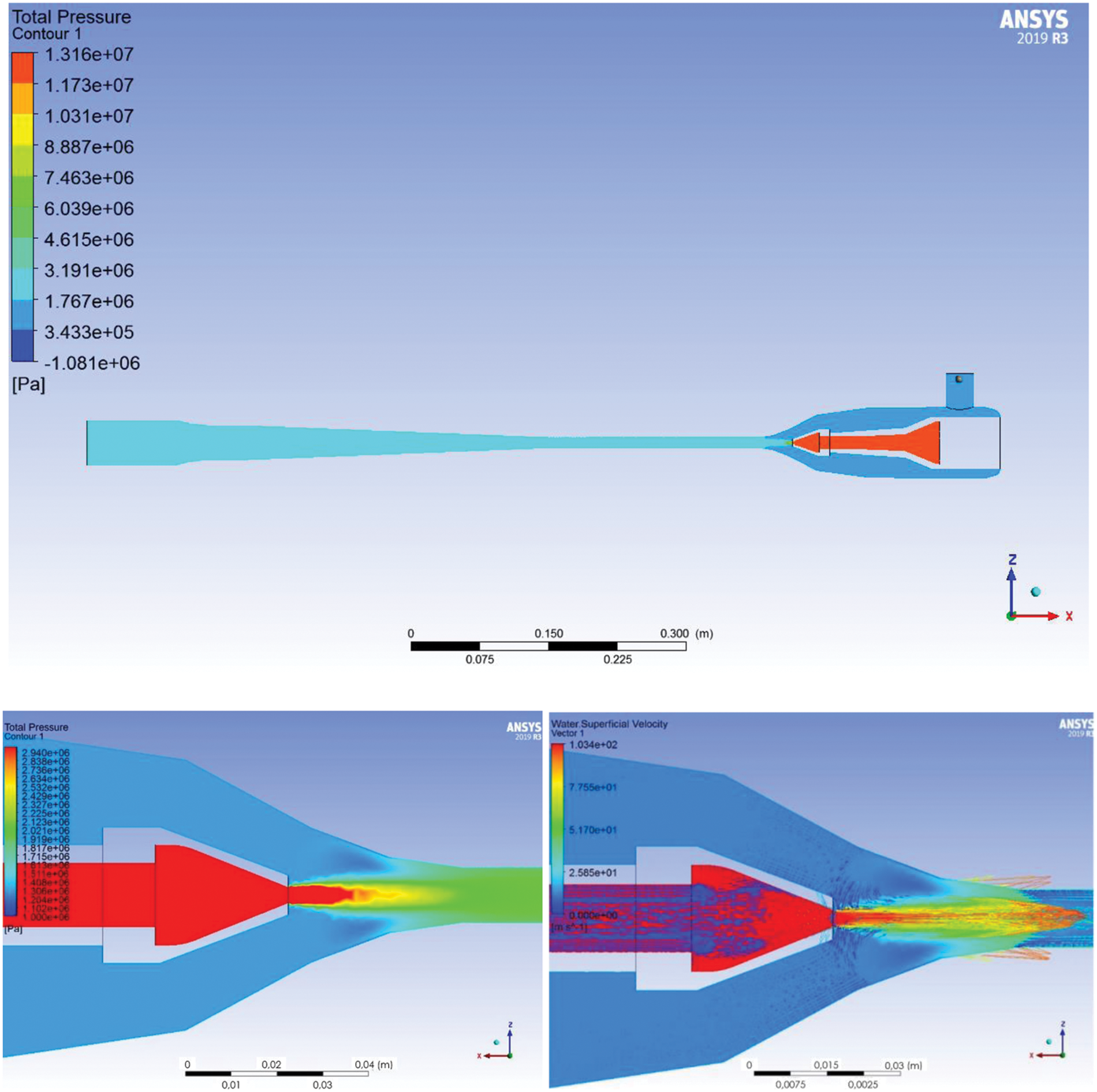
Figure 7: Jet pump pressure and water superficial velocity distribution (active medium: working agent-water; passive medium: gas-liquid mixture from Well #1)
3.4 Oil Production Increase Calculation Results
The operating parameters of the jet pump and Well #1 are given in Table 3.
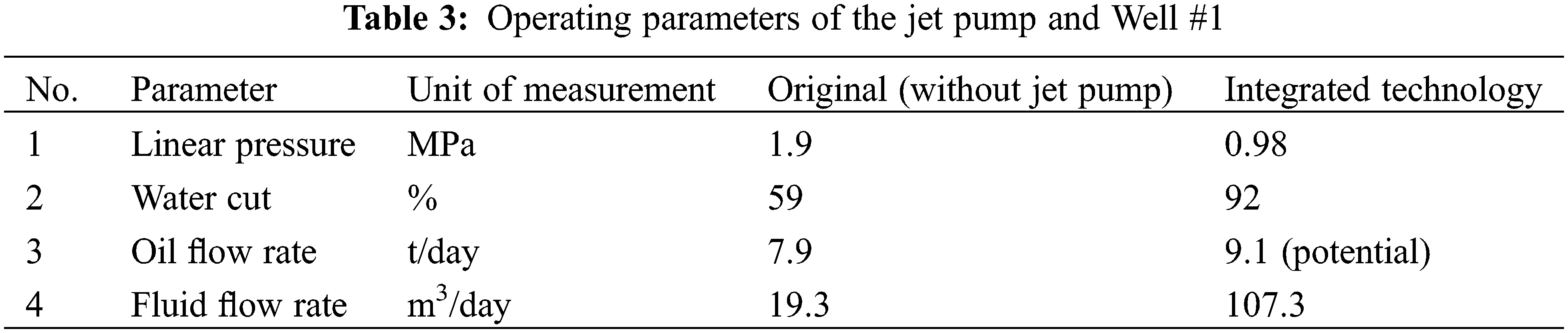
The result of the jet pump performance simulation is a decline in linear pressure from 1.9 to 0.98 MPa, which inevitably leads to annular pressure drop in producing Well #1. The water cut then increases from 59% to 92%, and the fluid production rate grows to 107.3 m3/day.
The theoretical flow rate increment due to the integrated technology will therefore be 1.2 t/day. This result is possible due to the annular pressure drop from 2.3 to 1.4 MPa.
1. The authors performed an extensive analysis of scientific and technical literature on the improvement of oil production and jet pump performance. The theoretical research resulted in a description and development of a process flow diagram of the waterflooding-based integrated enhanced oil recovery technology. Applicability criteria for the integrated technology were developed and the potential introduction target was selected. The integrated technology introduction target is a producing well with a 59% water cut.
2. The laboratory studies of the intensity of stable water-in-oil emulsions formation of the target object showed a growth in the emulsion dispersive capacity from 6.4 to 11.3 mm−1 as stirrer rotation speed increased from 1,500 to 3,000 rpm. This confirms the increase in emulsion stability. However, analysis of the water-in-oil emulsion separation kinetics showed the susceptibility of all emulsion types created to self-breaking up to the dehydration degree of 96–97% within a short time (6 min), which implies the impossibility of the formation of a stable emulsion when implementing the integrated technology.
3. The jet pump numerical simulation and calculation for the selected target showed a linear pressure decline from 1.9 to 0.98 MPa and an annular pressure drop from 2.3 to 1.4 MPa. Deep submergence of downhole pumping equipment under dynamic fluid level to a depth of 92 m allows for reliable operation of the submersible equipment, thus reducing the risk of downhole pumping equipment failure. The integrated technology ensures a 15% increase in the oil flow rate, i.e., additional daily growth of 1.2 tons for the selected target object.
4. Analysis of the mesh sensitivity shows that the finite mesh size affects the numerical simulation results. A mesh size of 2 mm or less leads to no change in the final result (linear pressure–as the resulting criterion in numerical simulation); however, a mesh size of more than 2 mm leads to a pressure drop at the jet pump outlet, leading to a more than 50% change in the final result.
5. Implementing the described technology will allow shifting the phase inversion point, i.e., increasing the water cut from 59% to 92%, which will promote hydrodynamic flow through the pipeline due to a decreased viscosity of the pumped fluid.
In view of the above, the authors successfully provided a rationale for the waterflooding-based integrated enhanced oil recovery technology, showed the main stages of scientific support of the integrated technology introduction, and proved the positive technological effect of its implementation.
CRediT Authorship Contribution Statement: Aleksandr Lekomtsev: Supervision, Writing-review & editing. Ivan Stepanenko: Data curation, Investigation, Writing-original draft. Vitaliy Bakaneev: Methodology, Resources. Petr Maximov: Editing after revision, Numerical modelling. Alexey Dengaev: Editing and review after revision. Yulia Rozhkova: Resources, Formal analysis. Wanli Kang: Writing–editing.
Funding Statement: The reported study was supported by the Government of Perm Krai, Research Project No. С-26/510.
Conflicts of Interest: The authors declare that they have no conflicts of interest to report regarding the present study.
References
1. Skalamera, М (2020). The 2020 oil price dive in a carbon-constrained era: Strategies for energy exporters in Central Asia. International Affairs, 96(6), 1623–1642. DOI 10.1093/ia/iiaa164. [Google Scholar] [CrossRef]
2. Connolly, R., Hanson, P., Bradshaw, M. (2020). It’s déjà vu all over again: COVID-19, the global energy market, and the Russian economy. Eurasian Geography and Economics, 61(4–5), 511–531. DOI 10.1080/15387216.2020.1776627. [Google Scholar] [CrossRef]
3. Filimonova, V., Kozhevin, V. D., Nemov, V. Y., Komarova, A. V., Mishenin, M. V. (2020). Supply as a factor in the destabilization of the oil market. Energy Reports, 6(8), 74–79. DOI 10.1016/j.egyr.2020.10.055. [Google Scholar] [CrossRef]
4. Hugo, L. P. (2020). The Gulf economies and the energy transition: The dawn of a post-oil era? Politique étrangère, 85(1), 19–31. [Google Scholar]
5. Suleimenova, А, Turkeyeva, K., Tulemetova, A., Zhanakova, N. (2020). The impact of the oil and oil products market on economic development: A national aspect. International Journal of Energy Economics and Policy, 10(5), 116–122. DOI 10.32479/ijeep. [Google Scholar] [CrossRef]
6. Tagirova, K. F. (2008). Povyshenie effektivnosti dobychi nefti na osnove koordinacii upravleniya tekhnologicheskimi processami i obektami (Improving the efficiency of oil production based on the coordination of technological processes and facilities management). Avtomatizaciya i Upravlenie Tekhnologicheskimi Processami i Proizvodstvami (Automation and Control of Technological Processes and Production Facilities), 10(2), 48–52. [Google Scholar]
7. Filippov, E. V., Chumakov, G. N., Ponomareva, I. N., Martyushev, D. A. (2020). Application of integrated modeling in the oil and gas industry. Subsurface Use, 20(4), 386–400. [Google Scholar]
8. Velichko, E. I., Polyakov, A. V., Dubov, V. V., Prikhodko, M. G. (2020). Improving the efficiency and transportation of high-viscosity oils by emulsification and creating a coaxial flow. IOP Conference Series: Earth and Environmental Science, 666(2), 022067. IOP Publishing. [Google Scholar]
9. Marinai, L., David, R., Di Sarra, A., Escorcia, A., Masud Akhtar, M. et al. (2020). Digital transformation of production governance and assurance process for improving production efficiency. Abu Dhabi International Petroleum Exhibition & Conference,OnePetro. [Google Scholar]
10. Ponomareva, I. N., Martyushev, D. A., Cherny, K. A. (2021). Research of interaction between expressive and producing wells based on construction of multilevel models. Bulletin of the Tomsk Polytechnic University-Geo Assets Engineering, 332(2), 116–126. DOI 10.18799/24131830/2021/02/3048. [Google Scholar] [CrossRef]
11. Syed, F. I. et al. (2021). Infill drilling and well placement assessment for a multi-layered heterogeneous reservoir. Journal of Petroleum Exploration and Production, 11(2), 901–910. DOI 10.1007/s13202-020-01067-0. [Google Scholar] [CrossRef]
12. Verbitsky, V. S. (2018). Method of applying acoustic impact to increase the energy efficiency of oil production by a mechanized method Pat. ROS. Federation, No. 2017102112. [Google Scholar]
13. Lekomtsev, A. V., Derendyaev, K. A., Burtsev, A. S., Stepanenko, I. B., Zhigarev, D. B. (2020). Utilization of ballast water produced along the way using the technology of well separation of oil-water emulsions. Bulletin of the Tomsk Polytechnic University-Geo Аssets Engineering, 331 (10), 178–186. [Google Scholar]
14. Ponomareva, I. N., Martyushev, D. A. (2021). Evaluation the volume of distribution of the injected water and the interaction between injection and production wells probabilistic and statistical methods. SOCAR Proceedings, (3), 54–62. DOI 10.18799/24131830/2021/02/3048. [Google Scholar] [CrossRef]
15. Chen, P., Al Sowaidi, A. K., Patel, H., Brantferger, K., Bin Buang, K. A. (2016). Assessment of simultaneous water and Gas injection SWAG pilot in a giant offshore carbonate reservoir. Abu Dhabi International Petroleum Exhibition & Conference, OnePetro, Abu Dhabi. [Google Scholar]
16. Khan, M. Y. et al. (2016). Water alternating gas WAG optimization using tapered WAG technique for a giant offshore Middle East Oil field. Abu Dhabi International Petroleum Exhibition & Conference, OnePetro, Abu Dhabi. [Google Scholar]
17. Li, Y., Liu, C., Bao, W., Xue, B., Lv, P. et al. (2022). Oil production optimization by means of a combined “Plugging, profile control, and flooding” treatment: Analysis of results obtained using computer tomography and nuclear magnetic resonance. Fluid Dynamics & Materials Processing, 18(3), 737–749 DOI 10.32604/fdmp.2022.019139. [Google Scholar] [CrossRef]
18. Khaibullina, K. S., Korobov, G. Y., Lekomtsev, A. V. (2020). Development of an asphalt-resin-paraffin deposits inhibitor and substantiation of the technological parameters of its injection into the bottom-hole formation zone. Periódico Tchê Química, 17(34), 769–781. DOI 10.52571/PTQ. [Google Scholar] [CrossRef]
19. Syuzev, A. V., Lekomtsev, A. V., Martyushev, D. A. (2018). Complex method of selecting reagents to delete asphaltenosmolaparinine deposits in mechanized oil-producing wells. Bulletin of the Tomsk Polytechnic University-Geo Assets Engineering, 329(1), 15–24. [Google Scholar]
20. Vyatkin, K. A., Martyushev, D. A., Lekomtsev, A. V. (2015). Technology of cleaning pump-compressor pipes from asphaltene-resin-paraffin deposits with the subsequent disposal. Oil Industry, 3, 36–38. [Google Scholar]
21. Lekomtsev, A. V., Turbakov, M. S., Mordvinov, V. A. (2011). Assessment of intensive paraffin accumulation depth in wells of Nozhovsky group oilfields. Oil Industry, 10, 32–34. [Google Scholar]
22. Aziz, H. et al. (2021). A review on nanofluid water alternating gas (N-WAGApplication, preparation, mechanism, and challenges. Arabian Journal of Geosciences, 14(14), 1–12. DOI 10.1007/s12517-021-07787-9. [Google Scholar] [CrossRef]
23. Khalilova, G. A., Yarkeeva, N. R. (2019). Emulsion breaking methods in oil production. Problems of Collecting, Preparing and Transporting Oil and Petroleum Products, 121(5), 28–32. DOI 10.17122/ntj-oil-2019-5-28-32. [Google Scholar] [CrossRef]
24. Manakova, Y. V., Ryabov, V. G., Ibraeva, E. V., Zakshevskaya, L. V., Siur, T. A. (2017). Screening for efficient agents for transportation and treatment of oil of south-khylchuiu field. Bulletin of the Perm National Research Polytechnic University-Geology. Oil and gas and Mining, 16(2), 164–173. DOI 10.15593/2224-9923. [Google Scholar] [CrossRef]
25. Ivanova, M., Tomskii, K. (2020). Effectiveness of demulsifiers for the destruction of highly mineralized water-oil emulsions of the Srednebotuobinsky oil and gas condensate field. E3S Web of Conferences, 04001. EDP Sciences. [Google Scholar]
26. Saad, M. A., Abdurahman, N. H., Yunus, R. M. (2021). Synthesis, characterization, and demulsification of water in crude oil emulsion via a corn oil-based demulsifier. Materials Today: Proceeding, 42, 251–258. [Google Scholar]
27. Peng, J., Liu, Q., Xu, Z. (2012). Masliyah novel magnetic demulsifier for water removal from diluted bitumen emulsion. Energy Fuels, 26, 2705–2710. DOI 10.1021/ef2014259. [Google Scholar] [CrossRef]
28. Sattorov, M. O., Yamaletdinova, A. A., Bokiyeva, S. K. (2020). Analysis of the effectiveness of demulsifiers used in the destruction of local water-oil emulsions. Universum: Technical Sciences: Electronic Scientific Journal, 4(73), 52–57. [Google Scholar]
29. Lambin, D. N. (2021). Tekhnologii nasosnoj ekspluatacii neftyanyh skvazhin s povyshennym soderzhaniem svobodnogo gaza i mekhanicheskih primesej (Technologies of pumping operation of oil wells with an increased content of free gas and mechanical impurities). Territory of Neftegaz, 12, 78–83. [Google Scholar]
30. Ageev, S. R., Dzhalaev, A. M., Berman, A. V., Kan, A. G., Osipov, M. L. et al.(2005). Equipment for oil production with a high content of free gas and experience of its operation. Society of Petroleum Engineers-Gulf Coast Section Electric Submersible Pump Workshop, Houston, USA. [Google Scholar]
31. Kvint, D. I. (2019). Analysis of modern oil production technologies in conditions of high values of the gas factor, heterogeneity and water content in the fields of Western Siberia (Bachelor’s work in the direction of 21.03.01 Oil and Gas), Tomsk Polytechnic University, Russia. [Google Scholar]
32. Lekomtsev, A. V., Mordvinov, V. A., Poplygin, V. V., Ponomareva, I. N. (2012). Efficiency of electric submersible pumps at extraction of the gas-liquid blends from wells. Oil Industry, 10, 132–133. [Google Scholar]
33. Mordvinov, V. A., Lekomtsev, A. V., Martyushev, D. A. (2014). Estimation of input pump pressure during low foaming gas-content oil pumping. Oil Industry, 6, 61–63. [Google Scholar]
34. Grekhov, I. V., Sultanov, S. K. (2012). Technology reserves difficult to recover from deposit with high gas-oil ratio. Oil Industry, 10(3), 10–14. [Google Scholar]
35. Grekhov, I. V. (2013). Complex of technical and technological solutions for oil production from heterogeneous multi-layer deposits with high gas content (Dissertation Candidate of Technical Sciences). Institute of Energy Resources Transport Problems, Ufa. [Google Scholar]
36. Verbitsky, V. S., Sataeva, A. F., Dengaev, A. V. (2015). Improving the energy efficiency of the esp in gas-liquid mixtures pumping conditions. Oil, Gas and Business, 11, 52–55. [Google Scholar]
37. Dengaev, A. V., Nikolaev, D. A., Verbitsky, V. S., Akopyan, B. A., Afanasiev, A. V. (2013). Application of ESP units in below packer zone while operating the wells in conditions of free gas. Oil, Gas, Innovations, 173(6), 52–55. [Google Scholar]
38. Drozdov, A. N., Verbitskiy, V. S., Dengaev, A. V., Arsenyev, A. A., Litvinenko, V. A. et al. (2008). Rotary gas separators in high GOR wells, field and lab tests comparison. Society of Petroleum Engineers-SPE Russian Oil and Gas Technical Conference and Exhibition, pp. 1394–1404. Russia. [Google Scholar]
39. Drozdov, A. N., Telkov, V. P., Egorov, Y. A., Verbitsky, V. S., Dengaev, A. V. et al. (2008). Solution of problems of water-gas influence on the layer using jet and electrical centrifugal pumping technology. Society of Petroleum Engineers-SPE Russian Oil and Gas Technical Conference and Exhibition, pp. 1–16. Russia. [Google Scholar]
40. Drozdov, A. N., Dengaev, A. V., Verbitsky, V. S. (2005). Ustanovki pogruzhnyh nasosov s gazoseparatorami dlya ekspluatacii skvazhin s vysokim gazovym faktorom (Installations of submersible pumps with gas separators for the operation of wells with a high gas factor). Territory Neftegaz, 6, 12–20. [Google Scholar]
41. Dengaev, A. V., Drozdov, A. N., Verbitsky, V. S., Markelov, D. V. (2005). Ekspluataciya skvazhin, oborudovannyh vysokoproizvoditel’nymi UECN s gazoseparatorami (Operation of wells equipped with high-performance ESPs with gas separators). Burenie i Neft (Drilling and oil), 2, 10–13. [Google Scholar]
42. Verbiskiy, V. S., Alexeev, Y. L., Igrevskiy, L. V., Dengaev, A. V., Grachev, V. V. (2013). New capabilities of pumping/ejection systems in oil production, in petroleum gas gathering and transportation. Oil, Gas, Innovations, 173(6), 60–63. [Google Scholar]
43. Drozdov, A. N., Chernishov, K. I., Shinkov, N. I., Gorbyleva, Y. A., Gorelkina, E. I. et al. (2020). Effect of working fluid temperature on the production of high-viscosity oil by hydro-jet-pump units (Russian). Oil Industry, 8, 87–91. [Google Scholar]
44. Drozdov, A. N., Verbitsky, V. S., Dengaev, A. V. (2004). Prespektivy primeneniya pogruzhnyh nasosno-ezhektornyh sistem v dobyche nefti (Prospects of using submersible pump-ejector systems in oil production). Nefterynok (Oil Market), 5, 76–81. [Google Scholar]
45. Mei, W., Peeran, S. (2017). Surface Jet pump trial test in safaniya field: Evaluation and case study. SPE Kingdom of Saudi Arabia Annual Technical Symposium and Exhibition, OnePetro, Dammam. [Google Scholar]
46. Yan, T., Zhao, X., Wang, X., Shi, Y., Yu, J. (2018). Study on energy conservation water injection system of offshore platform based on jet pump. Journal of Petroleum Science and Engineering, 170, 368–373. DOI 10.1016/j.petrol.2018.06.039. [Google Scholar] [CrossRef]
47. Drozdov, A., Krasilnikov, I., Verbitsky, V., Dengaev, A., Ipanov, A. et al. (2007). Test stand researches of the technology of preparation and pump up the water-gas mix in the layer with application the tubing ejecting systems. Drilling and Oil, 11, 20–23. [Google Scholar]
48. Peeran, S. M., Beg, N., Anazi, R., Ajmi, S. (2016). Using innovative surface mounted technology to boost production from low pressure oil wells and revive dead wells without any well intervention. Abu Dhabi International Petroleum Exhibition & Conference, OnePetro, Abu Dhabi. [Google Scholar]
49. Peeran, S. M., Anazi, R., Ajmi, S. (2016). A cost effective way to boost production from tight oil and gas fields using surface jet pump systems. Abu Dhabi International Petroleum Exhibition & Conference, Abu Dhabi. [Google Scholar]
50. Shurygin, M. N., Lavrinenko, A. A., Ponomarev, A. S., Pozdnyakov, A. S., Salikhova, A. R. et al. (2015). Case analysis of jet pump systems application in the oil and gas industry. Territory Neftegaz, 10, 80–87. [Google Scholar]
51. Drozdov, A. N. (2012). Opyt primeneniya i perspektivy razvitiya pogruzhnyh nasosno-ezhektornyh sistem (Experience of application and prospects of development of submersible pump-ejector systems). Territory of Neftegaz, 2, 86–88. [Google Scholar]
52. Mazilevsky, I. I, Apollova, A. V. (2017). Jet Pump: Pat. ROS. Federation, No. 169597. [Google Scholar]
53. Sazonov, Y. A. (2012). Jet Pump: Pat. ROS. Federation, No. 143832. [Google Scholar]
54. Sazonov, Y. A., Kazakova, E. S. (2012). Jet Pump: Pat. ROS. Federation, No. 120162. [Google Scholar]
55. Rakhmatullin, A. A., Hisametdinov, M. R., Rizvanov, R. Z., Petrov, N. M., Ganeeva, Z. M. et al. (2006). Jet Pump: Pat. ROS. Federation, No. 55027. [Google Scholar]
56. Tupalov, N. I. (2006). Jet Pump: Pat. ROS. Federation, No. 55440. [Google Scholar]
57. Dandani, M., Lepiller, V., Ghezal, A., Desevaux, P. (2018). Numerical visualizations of mixing enhancement in a 2D supersonic ejector. Fluid Dynamics & Materials Processing, 14 (1), 23–37. DOI 10.3970/fdmp.2018.014.023. [Google Scholar] [CrossRef]
58. Bouhanguel, A., Desevaux, P., Gavignet, E. (2015). Visualization of flow instabilities in supersonic ejectors using large eddy simulation. Journal of Visual Communication and Image Representation, 18, 17–19. [Google Scholar]
59. Garipov, O. M., Mustafin, E. L., Dengaev, A. V., Verbitsky, V. S., Garipov, M. O. (2020). Jet Pump: Pat. ROS. Federation, No. 196417. [Google Scholar]
60. Lekomtsev, A. V., Stepanenko, I. B., Derendyaev, K. A., Burtsev, A. S., Zhigarev, D. B. et al. (2021). Study of the ultrasonic treatment technology for destruction of stable water-oil emulsions in conditions of phase inversion. Chemical and Petroleum Engineering, 1, 3–6. DOI 10.1007/s10556-021-00886-0. [Google Scholar] [CrossRef]
61. Sobanov, A. A., Burnaeva, L. M., Galkina, I. V., Tudrii, E. V. (2011). Methodological guidelines for the course chemical technology (analysis of oil and petroleum products). Kazan (Volga Region) Federal University, Kazan. [Google Scholar]
62. Strunkin, S. I., Stepanov, Yu. G., Petrov, I. V., Shnurov, A. E. (2015). Primenenie blochno-kompressornyh ustanovok dlya otkachki gaza iz zatrubnogo prostranstva skvazhin s cel’yu optimizacii raboty GNO i uvelicheniya KIN (the use of block-compressor units for pumping gas from the annulus of wells in order to optimize the operation of the GNO and increase the KIN). Engineering Practice, 12. 1–7. [Google Scholar]
63. Patankar, S. V. (1980). Numerical heat transfer and fluid flow. Hemisphere Publishing Corp. USA. [Google Scholar]
64. Rhie, C. M., Chow, W. L. (1982). A numerical study of the turbulent flow past an isolated airfoil with trailing edge separation. AIAA Journal, 21(11), 1525–1532. [Google Scholar]
65. Majumdar, S. (1988). Role of underrelaxation in momentum interpolation for calculation of flow with nonstaggered grids. Numerical Heat Transfer, 13(1), 125–132. [Google Scholar]
66. Raw, M. J. (1996). Robustness of coupled algebraic multigrid for the navier-stokes equations. 34th Aerospace and Sciences Meeting & Exhibit, Reno. [Google Scholar]
Cite This Article
 Copyright © 2023 The Author(s). Published by Tech Science Press.
This work is licensed under a Creative Commons Attribution 4.0 International License , which permits unrestricted use, distribution, and reproduction in any medium, provided the original work is properly cited.
 Downloads
 Citation Tools