 Open Access
ARTICLE
Numerical Investigation of the Multiphase Flow Originating from the Muzzle of Submerged Parallel Guns
1 School of Mechatronics Engineering, North University of China, Taiyuan, 030051, China
2 School of Marine Science and Technology, Northwestern Polytechnical University, Xi’an, 710072, China
3 Northwest Institute of Mechanical Electrical Engineering, Xianyang, 712099, China
* Corresponding Author: Lin Lu. Email:
Fluid Dynamics & Materials Processing 2023, 19(10), 2707-2728. https://doi.org/10.32604/fdmp.2023.028641
Received 30 December 2022; Accepted 27 March 2023; Issue published 25 June 2023
Abstract
A two-dimensional model, employing a dynamic mesh technology, is used to simulate numerically the transient multiphase flow field produced by two submerged parallel guns. After a grid refinement study ensuring grid independence, five different conditions are considered to assess the evolution of cavitation occurring in proximity to the gun muzzle. The simulation results show that flow interference is enabled when the distance between the parallel barrels is relatively small; accordingly, the generation and evolution of the vapor cavity becomes more complex. By means of the Q criterion for vorticity detection, it is shown that cavitation causes the generation of vorticity and the evolution of the vapor cavity can result in an asymmetric distribution of vorticity for a certain distance of the barrels. In particular, the evolution of the vapor cavity can hinder the expansion of the gas and force it to flow outward, while an asymmetric distribution of vorticity can lead to a gas jet flowing outward and rotating simultaneously.Keywords
The muzzle flow field is usually the time-varying region of gas flow outside the muzzle due to gas expansion when a gun is launched, which is an unsteady and complex flow field with shock waves. Initially, the research on muzzle flow field mainly obtains the shadow image of muzzle flow field in artillery launching experiments by the electronic imaging method [1–3]. Based on the experimental results, the coupling relationship between the initial flow field and the propellant gas flow field is studied [4], the energy transfer relationship between them is analyzed. With the introduction and development of computational fluid dynamics (CFD) and high-performance multi-core computer technology, the numerical simulation method has the characteristics of low cost and high accuracy, which greatly promotes the development of muzzle flow field calculation technology. Cooke et al. [5] simplified the flow field as an axisymmetric model and calculated the shock wave when a 105 mm howitzer was launched. Dai et al. [6] analyzed the muzzle shock wave by numerical simulation, summarized the formation and function of the shock wave, and compared it with the experimental results. Cler et al. [7] used the computational fluid dynamics (CFD) software to simulate the muzzle flow field of a 7.62 mm rifle. The motion of the projectile was not considered in the simulation process. Su et al. [8] used CFD software and dynamic mesh technology to calculate the muzzle flow field of double barrel guns parallel launched at different distances. However, the launching process of the gun is in the air all the way. The flow field at the muzzle is relatively simple to launch under water and there is no multi-phase coupling in the air launch.
With the establishment and development of multiphase flow model and the
The sealed launch uses a special barrier to keep seawater out of the barrel, reducing resistance during the movement of the projectile in the bore and reducing the corrosion of the barrel, but after a sealed launch seawater will flow back into the bore, so the barrel needs to be drained and resealed before the next launch. In fact, both draining and sealing will waste a lot of time and are not conducive to underwater combat [13]. Under submerged parallel launch conditions, both the barrel and the external environment are filled with water. After the guns are launched, the projectile pushes the water column in front of the projectile forward, and the water column accelerates continuously, making the muzzle local pressure lower than the saturated vapor pressure of water, and the water at the muzzle is continuously vaporized into vapor, which accumulates at the muzzle and gradually becomes a cavity. The projectile will enter the cavity after flying out of the muzzle, and after a period of movement in the cavity, the projectile will re-enter the water. This process can be regarded as projectile entering water [14,15], so the cavitation evolution characteristics of a projectile can be studied by referring to the relevant projectile water-entry literature. The tests with different water-entry velocities [16] were conducted to study the effects of water-entry velocity on cylinders’ motion characteristics in process of them in parallel water-entry. Lu et al. [17] numerically investigated the water-entry characteristics of high-speed parallel projectiles, from which the influence of parallel projectiles entering water at different distance on the trajectory stability of projectiles and the evolution of flow field is revealed.
Most previous studies have focused on the experimentation and simulation of different underwater launch modes. The research on parallel launch is only on the flow field simulation of a double barrel machine gun launching in the air, and there is almost no related research on submerged parallel launch. Therefore, combined with the numerical simulation method and referring to the literature on parallel projectile launching into water and underwater launch, we established the physical model and numerical model of submerged parallel launch, verified the numerical method, the evolution process of muzzle flow field is studied, the generation and development of vorticity is analyzed by Q criterion, and the flow situation and reason for formation of gas jet were studied.
The assumptions made in this article are as follows:
1. The propellant in the parallel barrels chamber is ignited together, and the combustion of propellant gas follows the geometric combustion law. The geometric combustion law refers to the fact that during the combustion process of a grain, it is usually assumed that each ignition speed on the combustion surface is the same, and the variation of the combustion surface with time is similar to the Huygens principle of wave propagation, that is, each point on the combustion surface moves back in the normal direction perpendicular to the plane where the point is located, and the combustion follows the law of parallel layer retreat.
2. The air is regarded as ideal gas and its density is 998.2 kg·m−3. The density of vapor is 0.5542 kg·m−3. Both phases are considered incompressible fluids in this article
3. Because the numerical simulations use a two-dimensional axisymmetric model, only the evolution of the flow field at the muzzle is considered.
4. The impetus
5. The other factors are taken into account by adding a secondary work coefficient
6. This paper mainly studies the evolution of the complex flow field in the inner side of two barrels, and does not pay attention to the evolution of the flow field in the outer side.
7. Ignore the clearance and interaction forces between the projectile and barrels.
(1) Mass conservation equation
where subscript q = 1, 2, 3 represent different phases;
(2) Momentum conservation equation
In the equation, mixture density is
(3) Energy conservation equation
where E is the average value of energy; T is the average value of temperature;
2.2.2 Turbulence and Cavitation Models
(1) Turbulence models
In this paper the Realizable
where
(2) Cavitation models
where
2.2.3 Interior Ballistic Equation
(1) Form function of the propellant:
To calculate the muzzle flow field, the interior ballistic equation needs to be coupled. The interior ballistic equations are as follows:
where
(2) Law of the propellant burning:
where
(3) Momentum equation of projectile:
where
(4) Interior ballistics energy equation:
where
The submerged parallel launch process is simulated by using the CFD software with VOF model and the Schnerr-Sauer cavitation model. Combined with a user-defined function (UDF), the coupled interior ballistic equations of projectile velocity displacement and muzzle pressure are solved. In the computational model, the PRESTO! method is used for the discretization of the pressure gradient term; the second-order upwind method is used for the dispersing momentum and energy, and also employed in the turbulence and density equations. PISO algorithm is used to couple the pressure and velocity. To balance the calculation efficiency and accuracy, the time step is set to 1e-6 s. Using the layering method in the dynamic mesh technique, when the two meshes at the front of the projectile are compressed to half their initial size, the meshes will automatically merge into one mesh, and similarly, when the mesh behind the projectile is stretched to twice its initial size, the mesh will automatically split into two meshes. The algorithm flow for the coupled simulations is shown in Fig. 1.
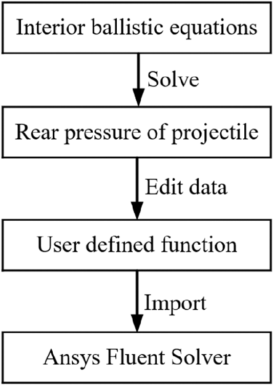
Figure 1: The algorithm flow for the coupled simulations
3 Verification of the Numerical Method
A review of the literature shows that there is a paucity of experimental data for submerged parallel launch. In this study, comparisons of the numerical simulation with an experiment and the photograph that was tested by Zhang et al. [11] are applied. The main parameters of the projectile are obtained by referring to the literature [11], as presented in Table 1, and the computational model of the projectile is shown in Fig. 2. The initial velocity of the projectile is 233 m/s. To ensure that the grid of the warhead part has sufficient accuracy and fit, the unstructured grid is used to fit the shape of the warhead, and the calculation is combined with the structured grid. The grid number is about 103321 and applied for the whole computational domain. Details of the computational domain grid are illustrated in Fig. 3.


Figure 2: Computational model of the projectile
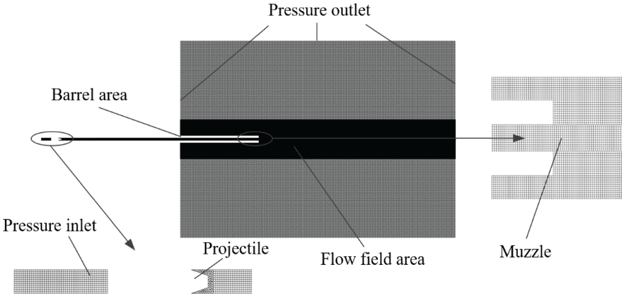
Figure 3: Computational domain, grids and boundary conditions
The numerical simulation results of the flow field at the muzzle at different moments are compared with the experimental photograph [11], as shown in Fig. 4. The cavity shapes simulated at three different moments agree with the experimental photograph. Fig. 5 compares the axial maximum displacement and the radial maximum displacement of the cavity at different moments with the experimental measurements. The numerical simulation result is agreed well with the experimental result.
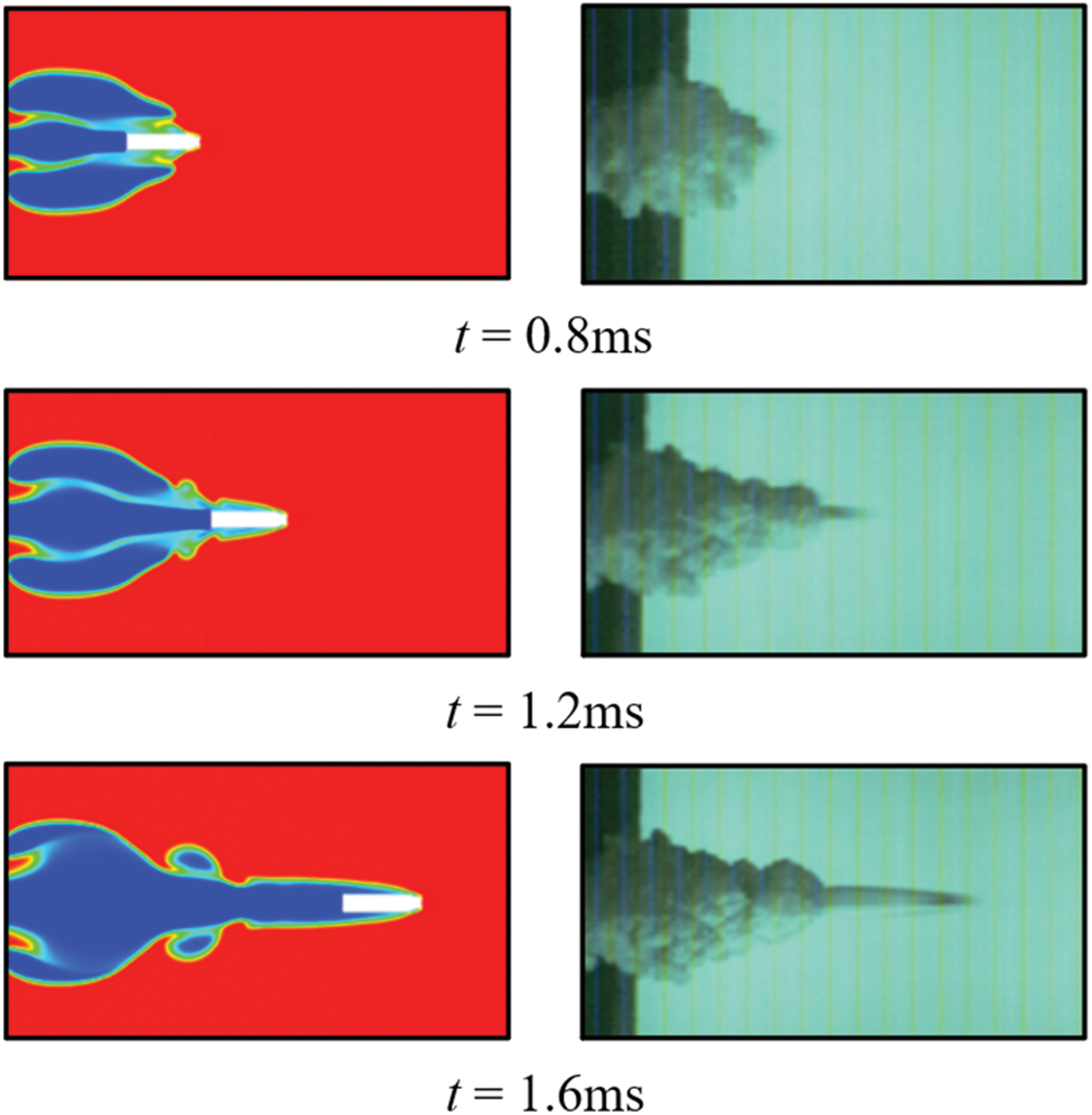
Figure 4: Experimental images and numerical results of submerged launch
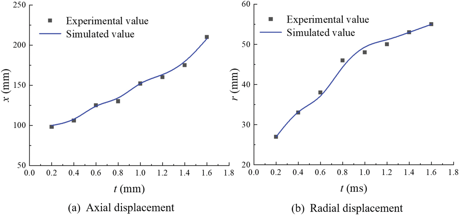
Figure 5: Displacement of the cavity during the submerged launch
4 Numerical Simulation Method Set-Up
4.1 Computational Model and Boundary Conditions
The computational model of the projectiles is a simple revolution body. The parameters of the projectile are listed in Table 2. Lp indicates the distance between the parallel barrels, as shown in Fig. 6. The area between the two barrels is defined as the inner side and the opposite side is defined as the outer side. The upper muzzle is referred to as Muzzle A and the lower muzzle as Muzzle B. To ensure that the launching conditions of the two barrels are completely consistent, a symmetry line is added between the two barrels to make the model symmetrical up and down. The mesh on one side is completely copied to the other side. The symmetry line is only used to copy the mesh. The two barrels are completely independent of each other and affect each other.


Figure 6: Computational model of the submerged parallel launch projectile
Fig. 7 shows the computational domain (43L2 in length, 79D1 in width), two parallel barrels on the left side of the computational domain. The projectile is moving along the +X-axis. The computational domain for simulation can be divided into two parts by the muzzle, including the barrel area and the flow field area.
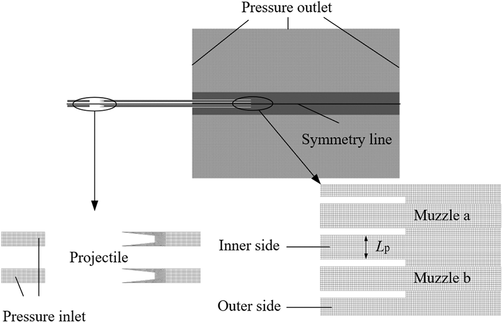
Figure 7: Computational grid for the submerged parallel launch
In this study, the setting of boundary conditions are illustrated in Fig. 8. The time variable is defined such that the bottom of the projectile flies out of the muzzle at time t = 0 ms.
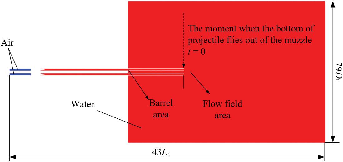
Figure 8: Computational domain for the submerged parallel launch
The quality of the computational grid is directly related to the accuracy and reliability of the numerical simulation results. In this study, the structured and unstructured grid generated is adopted for all the computational domains, as shown in Fig. 9. The total number of computational domain grids is 151110. Fig. 9 shows the grid division around the projectile. An unstructured grid is used at the warhead for local encryption, which can better fit the shape of the warhead. The structured and unstructured grids at the warhead are calculated together by the common node method. To accurately simulate the evolutionary characteristics of the flow field at the muzzle, the local grids around the muzzle and flow field are refined.
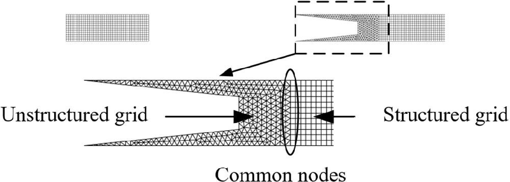
Figure 9: Grid generation around the projectile
4.3 Grid Independent Inspection and Grid Convergence Index
The grid independent inspection is carried out in order to ensure the accuracy and precision of numerical investigation of the submerged parallel launch. The computational grids are regenerated by changing the grid size around the muzzle. The regenerated grid sizes around the muzzle are 0.5 and 2 mm. The coarse grid number is 157213. The refined grid number is 252132. Fig. 10 shows the numerical results of the velocity attenuation of a single projectile along the X-axis after projectile ejection for Lp = 2D and v0 = 300 m/s. The velocity attenuation of the projectile is slightly faster for the coarse grid, while the difference in velocity attenuation between the other two grids is not significant, verifying the grid independence inspection. Considering the accuracy and efficiency of the numerical simulation, the grids number of 151110 was chosen for numerical simulation and analysis of the submerged parallel launch.
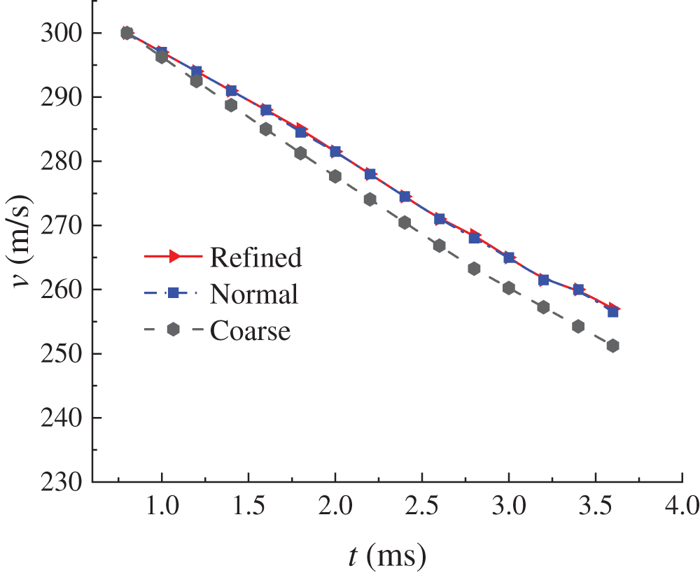
Figure 10: Velocity attenuation for different grid numbers
In addition, the Grid Convergence Index (GCI) is also applied and defined as follows:
where p is the accuracy order of the algorithm, r is the grid refinement factor between the fine and coarse grid, Fs is a safety factor. For Lp = 2D and v0 = 300 m/s, r =1.5 and Fs =1.25, the projectile ejection velocities of three kinds of grids are v1=286.23 m/s, v2 = 286.17 m/s, v3 = 286.11 m/s, respectively. p = 0.2006, GCIfine = 0.003050, GCIcoarse = 0.003589, GCIcoarse/GCIfine = 1.1767, which is approximately 1 and indicates that the grids are well within the asymptotic range of convergence.
5.1 Influence of the Submerged Parallel Launch on Muzzle Flow Field Characteristics (t < 0 ms)
When the projectile moves in the barrel (t < 0 ms), the evolution of the muzzle flow field is shown in Fig. 11. The projectile in the parallel barrels is accelerated together with the water column in front of the projectile by the propulsion generated by the gunpowder gas. The local water pressure at the muzzle decreases to the saturation vapor pressure, resulting in cavitation. The vapor formed by cavitation keeps accumulating at the muzzle, which is defined as vapor cavity. However, due to the different distance between parallel barrels, the evolution of the muzzle flow field at the inner side is different. When the submerged launch method is adopted, cavitation is generated close to the muzzle, and the vapor cavity is symmetrical. When the submerged parallel launch method is adopted, the vapor cavity generated by cavitation is asymmetric, and the cavitation generated at the inner area is far away from the muzzle.
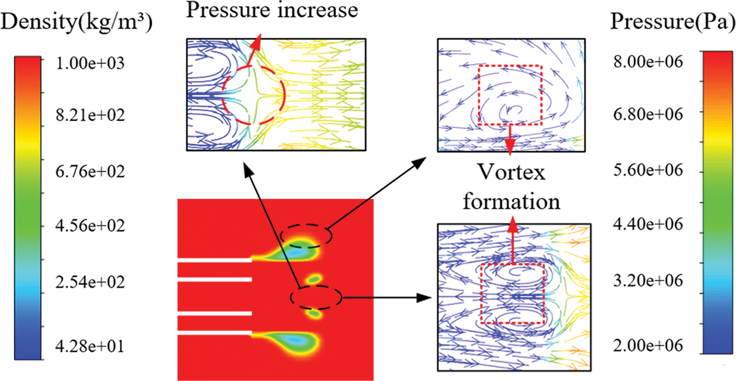
Figure 11: Density and pressure vectors of vapor cavity evolution
During the projectile ejection process, the evolution of vapor cavity and its mechanism is shown in Fig. 12. Under the condition of Lp = 2D, the water column is ejected from the barrel at a high speed. It at a much higher speed than the stationary water in the flow field area, so the stationary water is driven to move together with the ejected water. Therefore, the inner and outer side form two different vortices. In the absence of external force interference, the formation of the outer vortex is natural, so the outer vortex diameter is larger than the inner vortex diameter. From its shape, the vortex is disturbed. This is due to the close launch distance of parallel barrels and the convection of water ejected from the parallel barrels at the inner side in advance, which leads to local pressure rise and the formation of a high-pressure zone. As the water in the barrel is continuously ejected, the high-pressure zone moves in the direction of the water flow and the vortex becomes larger. Cavitation occurs earlier in the outer side, but in the inner side only after the formation of the vortex. After the high-pressure zone has moved for a distance, under the condition of Lp = 2D, cavitation occurs approximately 8 mm away from the muzzle. The existence of the vortex causes the flow field in the inner side to be more complex. Cavitation in the inner side is generated and eliminated several times under the influence of the complex flow field. With the change of the distance between parallel barrels, the position of cavitation on the inner side will be different, and the change rule will be given in the subsequent study.
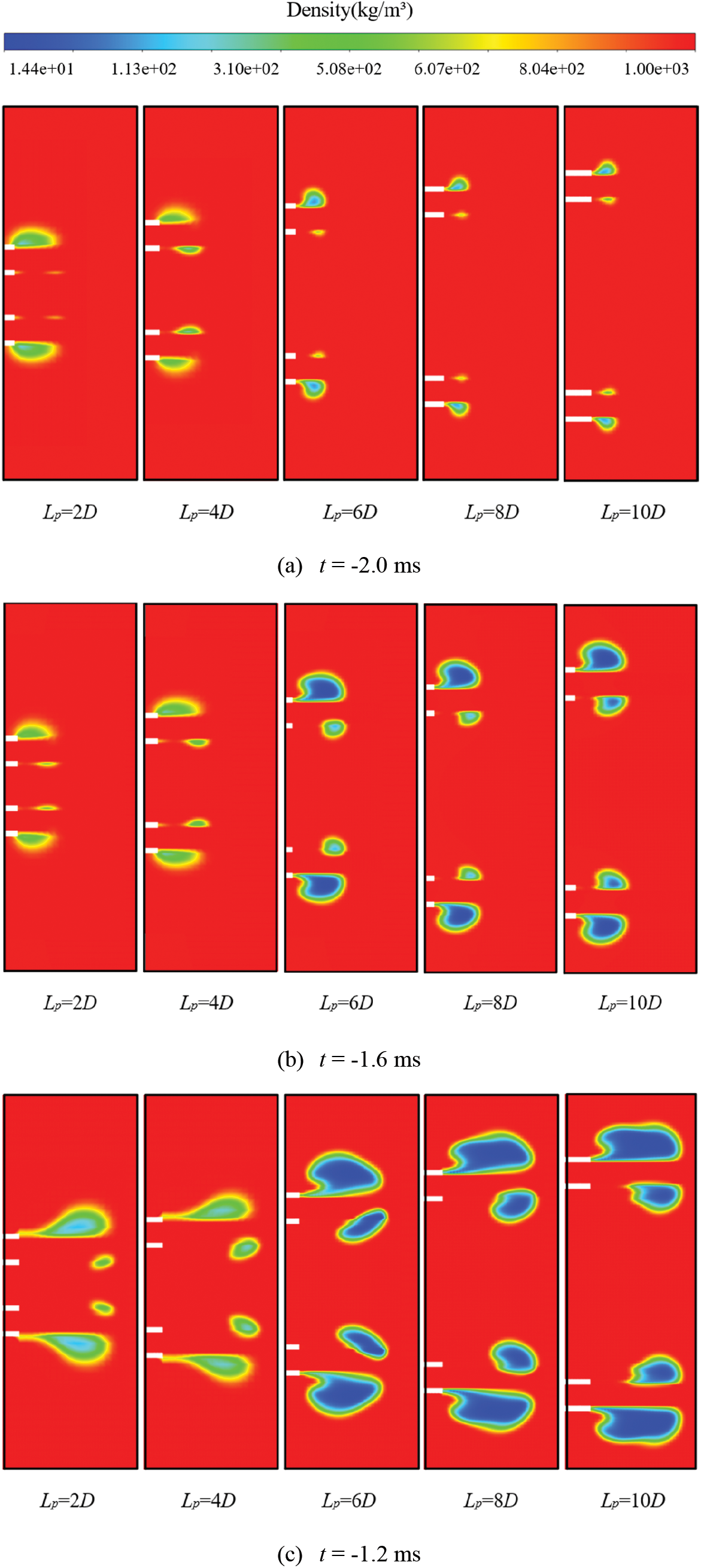
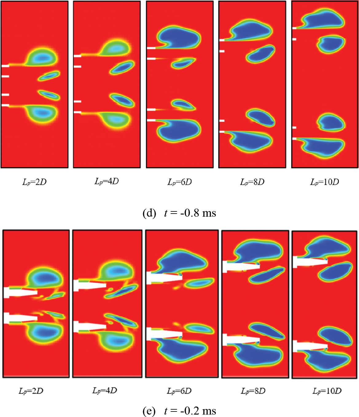
Figure 12: Numerical simulation of the evolution of the flow field at the muzzle (t < 0 ms)
When t = −2.0 ms, the flow field at the muzzle begins to generate cavitation. The cavity in the outer side is larger than the inner side and grows more easily. With the increase of distance between the parallel barrels (Lp), the position of cavitation in the inner side is closer to the muzzle. When Lp = 2D, the cavitation position is at its farthest distance from the muzzle, about 8 mm, and when Lp = 10D, the cavitation distance is the closest to the muzzle, it is about 2 mm.
When t = −1.6 ms and Lp = 6D–10D, it can be seen that, when the distance between barrels becomes relatively large, vapor cavity becomes lager. While Lp = 2D and 4D, there has no obvious difference and change under the influence of the complex inner side flow field.
In addition to the gradual growth and enlargement of vapor cavity. When t = −1.2 ms, the water column has shifted under the effect of the high-pressure zone in the inner side and the direction of movement has changed from the original along the axis to the outer side. The change of direction of water column movement makes the whole vapor cavity tend to grow to the outer side. The outward evolution of vapor cavity causes the warhead to wet in advance.
When t = −0.8 ms, the inner side of the vapor cavity wall is closer to the water column. When the water column continues to move along the axial direction, the inner side of the vapor cavity becomes longer in the axial direction, and then the inner side of the vapor cavity will collapse in the direction of the water column. However, under the condition of relatively large barrels distance, there is little influence on the evolution of vapor cavity. At this point, the cavity will further grow towards the inner side without collapse.
As shown in Fig. 11e, during the projectile ejection process, the projectile moves in the vapor cavity together with the water column. At this time, the water column decelerates under the resistance in the stationary water zone and continues to cavitate. The density of the water column is much smaller than the projectile. Although the water column and the projectile have the same speed at the time of ejection, the water column has less kinetic energy than the projectile, suffers relatively greater resistance, and its speed decays relatively faster. But because the water column loses the restraint of the barrel, the projectile discharges the water column toward the vapor cavity on both sides and at this time the resistance from the water column increases slightly. After that, the projectile discharges the water column, and then gradually enters the stationary water zone. At this time, the movement of the projectile is similar to the water-entry process of the projectile. In fact, the projectile will not move through two media with large density difference, so the resistance law of the projectile under the submerged parallel launch method is different from that of the projectile in the water-entry process.
To sum up, before the projectile ejection (t < 0 ms), the evolution of the muzzle flow field is mainly divided into four stages. The first stage is the cavity generation stage. In this stage, vapor cavity grows more easily with the increase of the distance between the parallel barrels. The second stage is the cavity growth stage. The cavity begins to grow in the radial direction of the barrel. However, due to the influence of the parallel barrels distance, the growth of the cavity is affected by the high-pressure zone and the inner side vortex flow field. When the parallel barrels distance is relatively small, the radial evolution of vapor cavity in the inner side is limited, causing the vapor cavity to collapse in advance. In the second stage, when vapor cavity grows in the radial direction, it compresses the direction of movement of the water column at the same time and causes the water column to move away from the axis direction towards the outer side. The whole vapor cavity begins to grow towards the outer side, which causes the wall of the vapor cavity in the inner side to move along the radial direction. The third stage is the local collapse or compression growth stage. When the distance between parallel barrels is Lp < 6D, the inner side wall of the vapor cavity cannot continue to grow radially, but is also elongated in the axial direction until collapse. When Lp ≥ 6D, the distance between parallel barrels is relatively large, and the space for growth of the vapor cavity becomes larger, which is conducive to the growth of the vapor cavity in the inner side. Therefore, the cavity is growing in the axial and radial direction at the same time. However, when the growth of the vapor cavity in the axial direction is natural, the growth in the radial direction is still limited, but the influence will not affect the ejection of the projectile from the muzzle, because the water column does not deflect and the inner side of the vapor cavity grows normally without collapse. Therefore, the resistance of the projectile will not change suddenly. The fourth stage is the stop growth stage. The vapor cavity experiences generation, compression, growth, and finally gradually stabilized, and no longer continues to grow significantly. At this time, the projectile is in the state of being about to be ejected, and then the water column is discharged and moves along the axial direction.
5.2 Influence of the Submerged Parallel Launch on Muzzle Flow Field Characteristics (t > 0 ms)
After the projectile flies out of the muzzle (t > 0 ms), the projectile enters the vapor cavity and moves for a period with the water column before reaching the stationary water zone. The warhead contacts the stationary water and transfers energy to the water, resulting in the local pressure in front of the projectile decreasing and formings cavitation. After that, the continuous cavitation forms a complete bubble wrapped projectile movement.
During the projectile movement, the numerical simulation results show that under different parallel barrels distance, the degree of impact on the projectile cavitation after launching is different. When the parallel barrels distance becomes larger, the influence on the cavitation is not obvious. As shown in Fig. 13, when the Lp = 4D, the liquid-vapor interface on the inner side receives compression. At the same time, when the warhead reaches the stationary water zone, the inner side of warhead is wetting, only the outer side of projectile cavitating. The compression effect of the inner side is gradually weakened with the increase of the distance between parallel barrels.
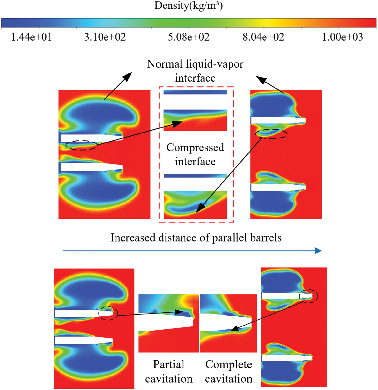
Figure 13: Density diagram of warhead cavitation
The main characteristics of the submerged parallel launch have been briefly described in the previous section, and the development of the muzzle flow field based on the simulation results will be analyzed and explained as follows. Under different parallel barrels distance, the biggest change in the evolution of the muzzle flow field is the change in the maximum diameter of the cavity. As shown in Fig. 14, when Lp = 2D, the inner side is compressed, and the development of the cavity is blocked, with the maximum diameter of 108 mm. With the increase of the distance, when Lp = 10D, the maximum diameter of the cavity is 126 mm. When Lp = 2D and 4D, the development of the flow field in the inner side eventually tends to expand inward, while the muzzle flow field of a normal single projectile is symmetrically expanding outward on both sides. The essential reason is that there is a high-pressure zone in the inner side, diving the inner side interface of the cavity to the interior of the cavity. The expelled interface does not intrude into the interior of the cavity too much, but takes on a regular shape similar to a straight line. This is because the development of cavitation is synchronized with the motion of the projectile in the process of the ejection of the projectile. The interface in the inner side of vapor cavity is close to the projectile, and it cannot continue to expand inward. Therefore, the inner boundary similar to a straight line will be formed. This phenomenon shows that under the distance of 2D and 4D, when the projectile moves in vapor cavity, it is affected by the inner high-pressure zone. When the distance is greater than 6D, although the inner interface is close to the inner surface of the projectile, it is always a certain distance from the inner side of the projectile.
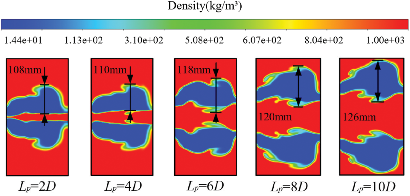
Figure 14: Density diagram of muzzle flow field
Fig. 15 shows the pressure vector around the projectile in Lp = 2D. As the projectile move through the vapor cavity and enters the stationary water zone, the water at the front of the projectile head is cavitated and ejected to both sides of the projectile. Therefore, at the center position of the inner side, this part of water simultaneously ejected from two projectiles to the inner side forms convection. At the same time, due to the close distance between the projectiles, the water convection between the projectiles compresses each other, forming a local high-pressure zone in the inner side. The presence of this area has an effect on the cavitation of the projectile.
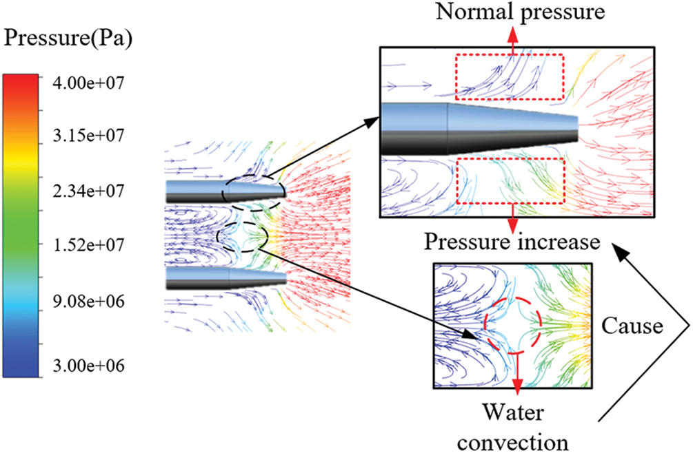
Figure 15: Pressure vector around the projectile
The states of complex motion of the fluid can be reflected through vortices of different scales and intensities distributed in space. According to the “Vortex dynamics and Turbulence” [18], the structure and evolution of the fluid flow is more economically described in terms of the vorticity field than in terms of velocity field. Vortices are important features that can accurately and effectively reflect the changes in the flow field. Therefore, it is of great significance to analyze the evolution process of cavity for studying the evolution mechanism of flow field in submerged parallel launch.
Q criterion can effectively identify the position and intensity of vortex [19]. The second invariant Q of velocity gradient tensor based on Galilean invariance is defined by Haller [20]:
where
When
As shown in the vorticity distribution in Fig. 16 identified by Q criterion, the vorticity at the muzzle is symmetrically distributed with respect to the barrel during submerged launch, while the vorticity at the muzzle is asymmetrically distributed with respect to the barrel during the submerged parallel launch. As mentioned above, when submerged parallel launch is conducted, the local pressure in the inner side will become higher when the distance between parallel barrels is small, thus affecting the evolution of vapor cavity.
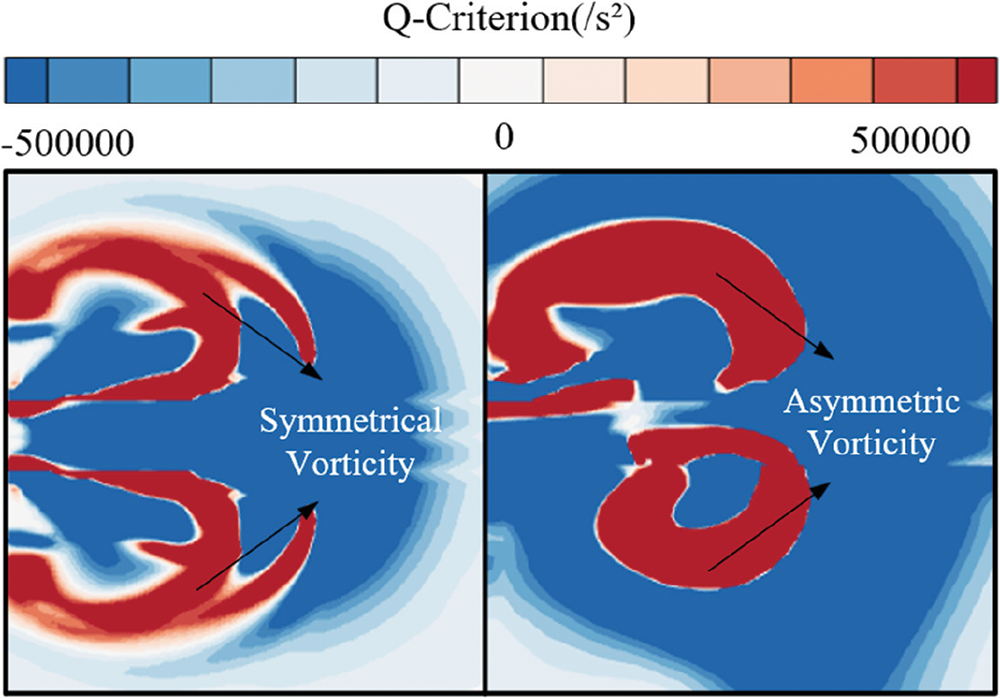
Figure 16: Muzzle vorticity comparison of two launch methods
When Lp = 2D is selected for observation, as shown in Fig. 17, the Q values on both sides of the cavity wall are positive during the cavity evolution process before the projectile ejected, indicating that the fluid around the cavity wall is rotating. During the movement of the projectile, the Q value in front of the projectile is always negative, which also indicates that the force between the projectile and the fluid in front is mainly in the form of shear, meeting the conditions for the fluid to start flowing. When cavitation occurs near the warhead, it can be observed that rotary vorticity is generated at the position where cavitation occurs. This shows that the generation of cavitation is related to the generation of rotary vorticity, and the generation of cavitation will cause the rotation of the fluid.
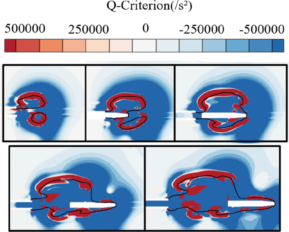
Figure 17: Vorticity diagram of the muzzle under the Q-criterion
Different from the generation of rotary vorticity at the muzzle before the projectile is ejected, the scale of the rotary vorticity generated near the warhead is small, and the rotary vorticity in the inner side is fluctuating and discontinuous, which is also due to the local high pressure in the inner side caused by the small barrel distance, which affects the generation of cavitation, thus affecting the generation of the rotary vorticity.
The flow field structure of the submerged launch is shown in Fig. 18. It is found from the observation of the gas jet after the projectile ejected that, as shown in Fig. 19, the shock wave structure after the gas jet is ejected from the muzzle is clear and regular, and obvious incident shock waves and reflected shock waves can be observed. However, under the condition of submerged parallel launch, the uneven evolution of vapor cavity limits the expansion of the gas jet, the shock wave structure is irregular, and the shock wave structure is not obvious. In addition, under the influence of the rotary vorticity in the cavity of the outer side, the gas jet no longer moves towards the direction of projectile motion, but diffuses to the outer side under the influence of the rotary vorticity. Therefore, the submerged parallel launch has an important influence on the expansion and evolution of gas jet.
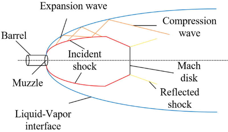
Figure 18: Schematic diagrams of the muzzle flow field flow for submerged launch
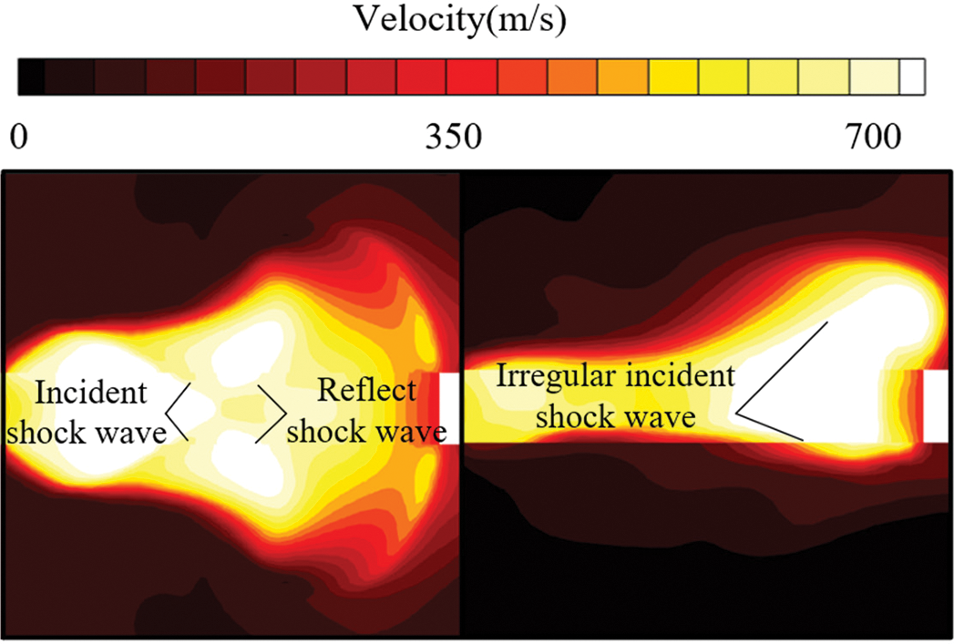
Figure 19: Comparison of the shock wave structures of gas jet with two launch methods
When the distance between parallel barrels changes, the flow of gas jet also changes. As shown in Fig. 20, with the increase of barrel distance, vapor cavity is easier to grow in the inner side, the expansion space of gas is larger, and the flow range is also larger. When submerged parallel launching, the gas jet always flows to the outer side, and with the increase of parallel barrels distance, the flow rate to the outer side first increases and then decreases. In addition to outward flow, under the action of rotary vorticity, the gas jet generates rotary flow, and the trend of rotary flow first increases and then decreases. The appearance of these two flow conditions is related to the evolution of vapor cavity. When the development of the inner side of vapor cavity is limited, the outward flow and rotary flow trends are very weak. As vapor cavity in the inner side becomes larger, both trends are gradually strengthened and then gradually weakened until they disappear.
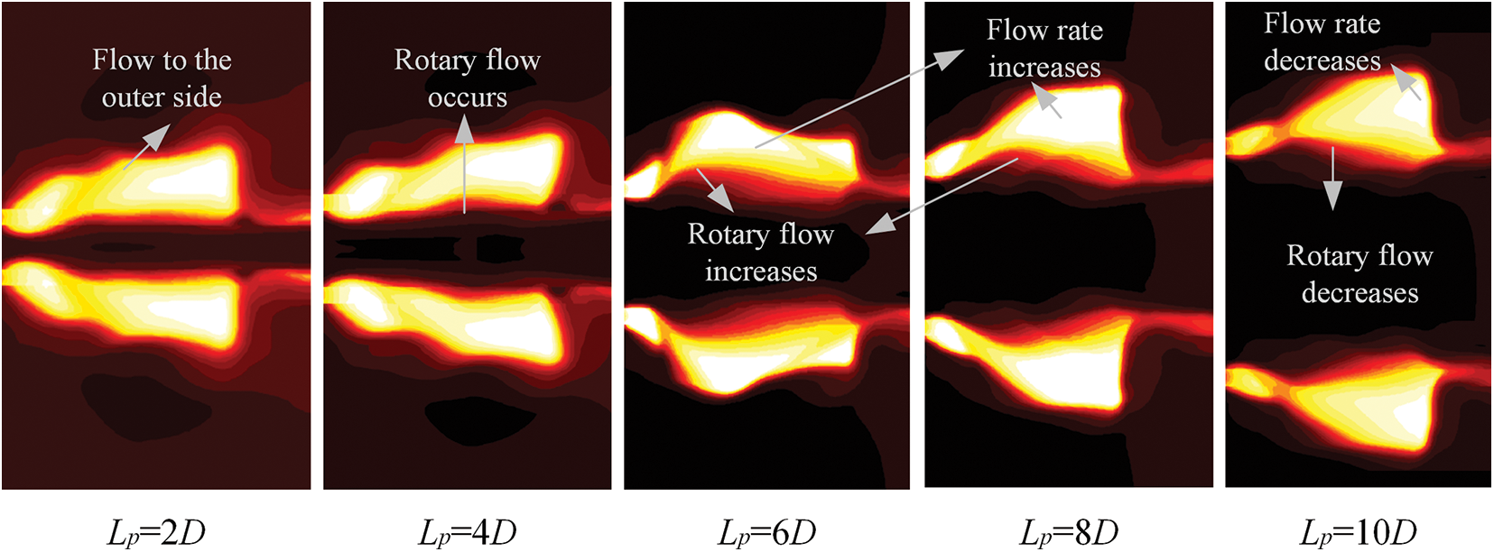
Figure 20: Gas jet flow at different parallel barrels distance
The analysis of the drag on the projectile after projectile ejection at different moments for different values of Lp is shown in Fig. 21. The water column speed decreases rapidly when it is ejected from the barrel due to the resistance in the stationary water zone. The projectile needs to press the water column apart and move along the axial direction. The relative speed between the projectile and the water column becomes larger and larger. Therefore, the projectile needs to consume more kinetic energy to discharge the water column. The resistance of the projectile increases continuously. However, when Lp < 6D, the water column is bent due to the compression of vapor cavity in the inner side, resulting in different contact conditions between the two sides of the warhead and water column. When Lp = 2D, the inner side of the vapor cavity collapses and the inside of the warhead becomes wet, so the resistance increases before entering the stationary water zone and increases significantly after completely pressing the water column into the stationary water zone. However, when the Lp increases gradually, the asymmetric wetting of the warhead will not occur, so the resistance will not increase in advance, but will increase abruptly when entering the stationary water zone after pressing the water column apart, and the drag growth rate will become faster thereafter. It can be seen from that when Lp ≥ 6D, the change of the projectile resistance is closer to the case of single launch, and the maximum resistance is also significantly less than the working condition of Lp < 6D, and the interference of the resistance in the process after the projectile ejection movement is small. Therefore, when Lp > 6D, the muzzle flow field has little impact on the projectile’s movement after it is ejected from the barrel. So, the basic condition that the resistance has no great influence on submerged parallel launch is that the distance between barrels Lp ≥ 8D.
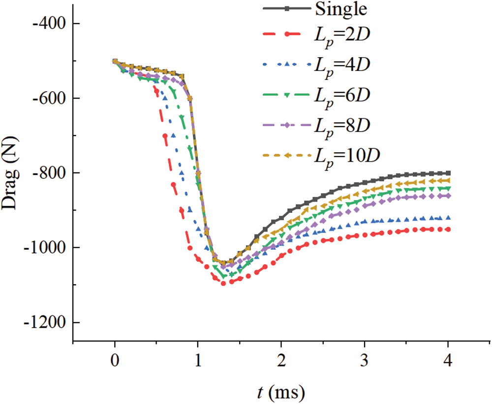
Figure 21: Variations of the drag along the X-axis for different values of Lp
In this study, the muzzle multiphase flow field using the submerged parallel launch method has been investigated numerically by using the Schnerr-Sauer cavitation model and the Realizable
1. Under the condition of submerged parallel launch, the expansion of the vapor cavity to the inner side before ejection of projectile is restrained. Due to the strong interaction between muzzle flow fields, the distribution of the vapor cavity is not uniform, and the cavity will collapse under the action of the water column and internal complex flow field, resulting in the wetting of the warhead.
2. During the submerged parallel launch, a local high-pressure zone occurs in the flow field between parallel barrels. When the water column ejects from the barrel at a high speed, it brings the water around the muzzle to flow, and forms a convection in the inner side, thus forming a local high-pressure zone. Before the projectile ejection, the local high-pressure zone affects the generation of inner side of the vapor cavity. When the distance between the parallel barrels becomes larger, the influence of the inner high-pressure zone is weakened.
3. The evolution of flow field at the muzzle during launching is analyzed. It is concluded by vorticity analysis that different parallel barrels distance causes asymmetric distribution of vorticity. Similarly, the evolution difference of the cavity leads to the flow changes of the gas jet. The asymmetric evolution of the cavity also leads to the flow changes of the gas jet. The asymmetric evolution of the cavity affects the expansion of the gas jet and makes the gas jet flow to the outer side. The asymmetric evolution of vorticity causes the gas jet to rotate in the process of outward flow.
Funding Statement: This work is supported by the National Natural Science Foundation of China (Grant No. 52201385), the Natural Science Foundation of Shanxi Province (Grant No. 20210302123023), and the Shanxi Scholarship Council of China (Grant No. 2020-106).
Author Contributions: Dongxiao Zhang: Supervision, Writing-review & editing, Methodology. Lin Lu: Investigation, Software, Data curation. Xiaobin Qi: Editing, Investigation. Xuepu Yan: Supervision, Editing. Cisong Gao: Investigation, Software. Yanxiao Hu: Software, Editing.
Availability of Data and Materials: The data that support the findings of this study are available from the corresponding author upon reasonable request.
Conflicts of Interest: The authors declare that they have no conflicts of interest to report regarding the present study.
References
1. Schmidt, E. M., Gordnier, R. E. S. (1984). International of gun exhaust flow field. AIAA Journal, 22(4), 1697–1710. [Google Scholar]
2. Schmidt, E. M. (1975). Shear D3D. Measurement of muzzle blast. AIAA, 13(8), 1086–1091. [Google Scholar]
3. Schmidt, E. M. (1984). Muzzle blast pressure loadings upon aircraft surfaces. Army Ballistic Research Lab Aberdeen Proving Ground MD. [Google Scholar]
4. Fansler, K. S., Schmidt, E. M. (1982). The relationship between interior ballistics, gun exhaust parameters and the muzzle blast overpressure. AIAA. [Google Scholar]
5. Cooke, C. H., Fansler, K. S. (1986). TVD calculations of blast wave from a shock tube and 105 mm Howitzer. Proceedings of the 9th International Symposium on Ballistics, pp. 37–44. Airlington, VA, American Defense Preparedness Association. [Google Scholar]
6. Dai, S. L., Xu, H. Q., Sun, L. (2007). Numerical simulation of gun muzzle flow field including movable boundary. Journal of Ballistics, 19(3), 93–96. [Google Scholar]
7. Cler, D. (2003). CFD application to gun muzzle blast–A validation case study. 41st Aerospace Sciences Meeting and Exhibit, AIAA 2003–1142. [Google Scholar]
8. Su, X. P., Qian, L. F., Dai, J. S. (2009). Numerical simulation of muzzle flow field of a gun with muzzle device. Computer Simulation, 26(9), 15–18. [Google Scholar]
9. Cheng, Y. S., Liu, H. (2007). A coupling model of water flows and gas flows in exhausted gas bubble on missile launched underwater. Journal of Hydrodynamics, 19(4), 403–411. [Google Scholar]
10. Zhang, X., Yu, Y., Zhang, X. (2021). Analysis of muzzle flow field characteristics of guns fired in different media. Explosion and Shock, 41(10), 103–114. [Google Scholar]
11. Zhang, J. H., Yu, Y. G., Zhang, X. W. (2022). Numerical investigation of a muzzle multiphase flow field using two underwater launch methods. Defence Technology, 18(8), 1454–1469. [Google Scholar]
12. Zhang, X., Yu, Y., Zhou, L. (2019). Numerical study on the multiphase flow characteristics of gas curtain launch for underwater gun. International Journal of Heat & Mass Transfer, 134, 250–261. [Google Scholar]
13. Meng, X., Hou, J., Wei, P., Liao, F. (2020). Overview of launching technology of underwater gun. Armament Automation, 39(5), 84–89+96. [Google Scholar]
14. Shentu, J., Zhao, T., Li, D., Zhao, X. (2019). Numerical simulations for water entry of hydrophobic objects. Ocean Engineering, 190(3), 106485. [Google Scholar]
15. Nguyen, V. T., Phan, T. H., Duy, T. N., Park, W. G. (2021). 3D simulation of water entry of an oblique cylinder with six-degree-of-freedom motions using an efficient free surface flow model. Ocean Engineering, 220, 108409. [Google Scholar]
16. Lu, L., Wei, Y., Wang, C., Song, W., Liu, K. (2019). Tests for cavities and motion characteristics in process of two cylinders in parallel water entry at low speed. Journal of Vibration and Shock, 38(7), 42–49. [Google Scholar]
17. Lu, L., Wang, C., Li, Q., Sahoo, P. K. (2021). Numerical investigation of water-entry characteristics of high-speed parallel projectiles. International Journal of Naval Architecture and Ocean Engineering, 13(3), 450–465. [Google Scholar]
18. Saffman, P. G. (1991). Vortex dynamics and turbulence. US: Springer. [Google Scholar]
19. Hunt, J. C., Wray, A. A., Moin, P. (1988). Eddies, streams, and convergence zones in turbulent flows. Proceedings of the Summer Program 1988, Center for Turbulence Research. [Google Scholar]
20. Haller, G. (1999). An objective definition of a vortex. Journal of Fluid Mechanics, 525, 1–26. [Google Scholar]
Cite This Article
 Copyright © 2023 The Author(s). Published by Tech Science Press.
This work is licensed under a Creative Commons Attribution 4.0 International License , which permits unrestricted use, distribution, and reproduction in any medium, provided the original work is properly cited.


 Submit a Paper
 Propose a Special lssue
 View Full Text
 Download PDF
 Downloads
 Citation Tools