
 Submit a Paper
 Propose a Special lssue
 Open Access
ARTICLE

Influence of Spray Gun Position and Orientation on Liquid Film Development along a Cylindrical Surface
School of Mechanical Engineering, Yancheng Institute of Technology, Yancheng, 224051, China
* Corresponding Author: Yong Zeng. Email:
(This article belongs to the Special Issue: CFD Modeling and Multiphase Flows)
Fluid Dynamics & Materials Processing 2023, 19(10), 2499-2518. https://doi.org/10.32604/fdmp.2023.028413
Received 20 December 2022; Accepted 14 March 2023; Issue published 25 June 2023
 View Full Text
 Download PDF
Abstract
A method combining computational fluid dynamics (CFD) and an analytical approach is proposed to develop a prediction model for the variable thickness of the spray-induced liquid film along the surface of a cylindrical workpiece. The numerical method relies on an Eulerian-Eulerian technique. Different cylinder diameters and positions and inclinations of the spray gun are considered and useful correlations for the thickness of the liquid film and its distribution are determined using various data fitting algorithms. Finally, the reliability of the proposed method is verified by means of experimental tests where the robot posture is changed. The provided correlation are intended to support the optimization of spray-based coating applications.
Graphic Abstract

Keywords
At present, with the rapid development of automation technology and information technology, robot spraying has gradually replaced manual spraying and is widely used in the coating process in the manufacturing environment of the automobile, aviation, aerospace, shipbuilding, and other industries. It is the basis for realizing numerical control (NC) of spraying trajectory planning for spraying robots using off-line programming to clarify the rules of coating formation and building a prediction model of coating thickness distribution [1].
With the development of computational fluid dynamics (CFD) [2], In theory, the simulation of the spray film-forming process under various conditions can be explained by combining CFD with experimental data [3–5]. Conner et al. [6] and Zhao et al. [7,8] established a mathematical model for electrostatic air spraying film thickness distribution based on plane analysis of the influence of the moving speed of the electrostatic rotating cup on film distribution. However, the established model does not consider the influence of the position and orientation of the spray gun on film distribution, and is only applicable to the electrostatic rotary cup spray gun and cannot be applied to the air spray gun. Once the spray gun changes, the model will no longer be applicable. Because the gas field, fog field, and shooting range of air spraying are important factors affecting the transfer of coatings and the quality of film formation, scholars have tried to reveal the film formation mechanism and characteristics of air spraying under the action of three fields. For example, Fogliati et al. [9] considered the influence of gas and fog fields, and used the Lagrangian method to simulate the transfer and film formation process of paint on the plane. Barry et al. [10] used the realizable k-ε turbulence model to simulate the process of a single jet impinging on the target plane, aiming at the influence of airflow, spraying height, and other parameters on the film deposition during the impingement process of an air spraying jet. Garbero et al. [11] found that the higher the viscosity of the coating, the less the rebound or splash phenomenon of the atomized droplets hitting the solid surface. Tafuri et al. [12] obtained the film thickness distribution map by recording the position and mass of the droplet impacting the surface. However, these studies were all carried out for planar spraying, and the influence of curved shooting ranges on film formation has not been studied, so the research were not comprehensive enough. Chen et al. used the Euler-Euler method [13–15] and the Euler-Lagrangian method [16] to study the film forming mechanism and characteristics of different arc surfaces [17] and spherical surfaces [18], respectively. However, their research results were only obtained under the condition that the spray gun is perpendicular to the surface and at a fixed position, whereas the influence on the film formation law when the spray gun position and attitude (height and angle) parameters change was not considered. Their research results are far from meeting the needs of variable spraying on complex surfaces. Therefore, it is urgent to clarify the influence of the position and posture of the spray gun on the film formation law of complex surfaces.
Improving the quality of robot spraying on complex surfaces has always been a hot and difficult research topic [19]. As a common surface type in industrial product design, the cylindrical surface is widely used in various equipments and facilities. Compared with the plane, the cylindrical surface has a greater impact on the spray flow field shape, film thickness uniformity, and coating adhesion [20]. Studying the characteristics of cylindrical spray film formation and modeling spray film formation is of great significance for revealing the film formation law of complex free-form surfaces, optimizing the trajectory parameters of spray guns, and improving the quality of spraying [21–25].
In this paper, firstly, the Euler-Euler method is used to establish the static spraying film-forming model of a cylinder surface, and CFD numerical simulation is used to compare and analyze the spray flow field morphology and film thickness distribution of different diameter cylinders at different spraying heights and spraying angles and reveal the influence law of film thickness distribution. Within the thickness range to ensure film forming quality, the adjustable range of spray gun position and posture for different diameter cylinders is established according to the influence law of film thickness distribution and the variable range of spray height. Then, based on the Gauss sum model, a prediction model of the coating thickness distribution model for static posture changing spraying of cylindrical surfaces with different diameters is established. Finally, the validity and feasibility of the numerical simulation method and the film thickness distribution prediction method are verified by robot spraying experiments.
2 Calculation Model and Numerical Simulation
During the spraying process, the paint is torn into a liquid film under the effect of air disturbance for the first atomization. When the liquid droplets after the first atomization meet the high-speed air flow from the auxiliary atomization hole on the air nozzle, the difference in velocity between the two will cause secondary atomization of the liquid droplets, and then the paint droplets will attach to the workpiece surface to form a film under the drive of high-speed air. The spray film-forming model includes the spray flow field model and the impact adhesion model. The spray flow field model describes the mixed transport process of gas and liquid phases, and the impact adhesion model describes the process of coating impaction and adherence to the workpiece surface.
By establishing the conservation equation of the spray gun spray flow field, the complex gas flow and paint particle movement in the flow field during spraying can be expressed mathematically, which is the starting point and theoretical basis for the numerical calculation of spray gun spraying process.
The mass conservation equation is expressed as:
The momentum conservation equation is expressed as:
In Eqs. (1) and (2), αq, ρq, and vq represent the volume fraction of q phase, gas phase density, and gas phase velocity respectively. When q is l or g, it represents the coating phase and air phase, respectively. P is the shared pressure, τq is the viscous stress of the gas phase, g is the gravity, Fqtd is the turbulent dispersion force per unit volume of the gas phase, and Fq is the interphase force per unit volume.
The interphase force Fq is the sum of the drag force Fd, the lifting force Fl and the virtual mass force Fv. This study ignores the lifting force Fl and the virtual mass force Fv, and only considers the drag force caused by the difference in speed between the two phases.
In (3), Cd is the drag coefficient, which is taken as 0.44 in this study.
In this study, the Reynolds average method is used to solve turbulent flow. The viscous vortex model does not directly solve the Reynolds stress term, but is expressed as a function of turbulent viscosity μt Turbulence viscosity can be calculated by the following formula:
In (4), ρ is the fluid density; Cμ is the constant, which is taken as 0.09 in this study.
The gas-liquid two-phase motion in the spray flow field is complex, and fluctuations in velocity occur. It takes a lot of computational effort to instantaneously express the turbulence. The standard k-ε is introduced in the numerical calculation Turbulence model, the model integrates turbulent kinetic energy and diffusion rate, and its corresponding transport equation is:
In the formula, ρm is the mixed phase density, νm is the mixed phase velocity, µt,m is the molecular viscosity, Gk,m is the turbulent kinetic energy generation term, C1ε and C2ε are constants, and Πkm and Πεm are additional terms of turbulence between two phases.
In the spraying flow field, the paint droplets adhere to the wall and form a liquid film under the action of air. The liquid film satisfies the mass conservation equation and the momentum conservation equation.
The mass conservation equation is expressed as:
In the formula, ρl is the film density, h is the film height, Vl is the average film speed,
The momentum conservation equation is expressed as:
In Eq. (9), the left side is the transient term and convection term, respectively; The first term on the right side of the equation represents the effect of air flow pressure and liquid film surface tension; The second item represents the action of viscous shear force at the interface of air coating film; The third item represents the role of viscosity in the film; and the fourth item represents the momentum source effect of the liquid film. In Eq. (10), Vd is the liquid phase velocity vector.
2.2 The Static Spray Simulation Calculation
2.2.1 Computing Domain Setting and Mesh Division
The nozzle cap model of the air spray gun is established. The center of the spray cap is a coating hole with a hole diameter of 0.8 mm. The outside of the coating hole is a center atomization hole with an outer diameter of 2.0 mm and an inner diameter of 1.6 mm. Two auxiliary atomization holes are arranged on both sides of the central atomization hole with a hole diameter of 0.5 mm. Two fan control holes are placed on the horn structure on both sides of the air cap with a hole diameter of 0.8 mm. Fig. 1 shows the spray gun and its spray cap model, respectively.
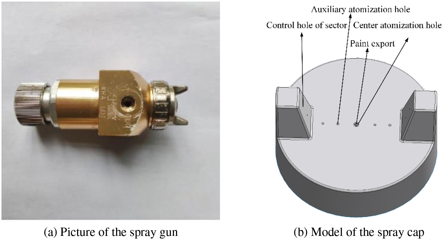
Figure 1: Spray gun and its spray cap model
According to the need of changing the cylindrical diameter and the position and attitude of the cylinder, this study uses the spray method of changing the position and attitude to conduct numerical simulations for cylinders with different diameters. The cylindrical diameters are 400, 500, and 600 mm, respectively. According to the process requirements of the spray gun, the allowable adjustable range of spraying height is 200–300 mm, and the preset adjustable range of spraying angle is 0°~30°. For different spraying heights, spraying angles, and cylindrical diameters, different control domains need to be set for the simulation calculation.
The computational domain of spray flow field is divided into unstructured grids. Considering the calculation accuracy and convergence speed, the local mesh of the cylindrical surface and spray gun is locally densified. The computational domain grid is divided by the global grid size control. The computational domain model and grid division are shown in Fig. 2.
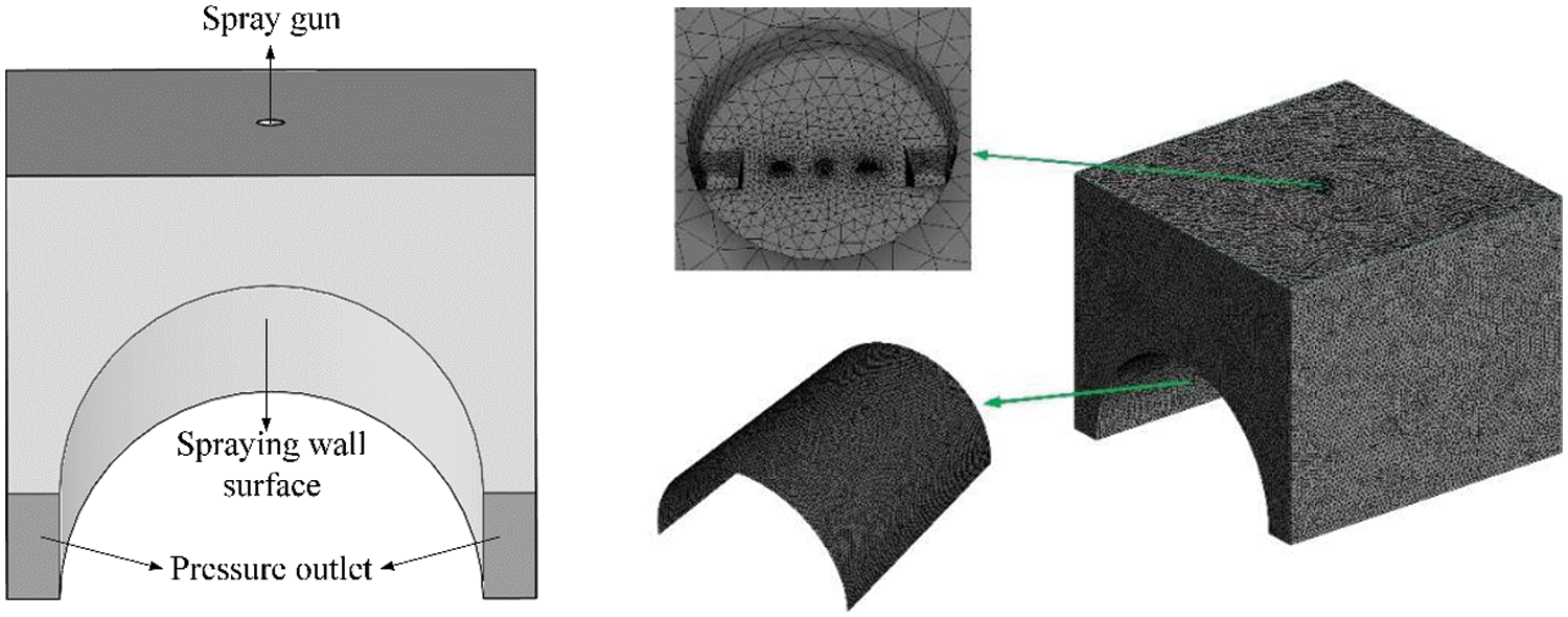
Figure 2: Computational domain model and mesh division of the spray gun and its spray cap model
Table 1 shows that when the number of grids exceeds 1546917, the liquid phase velocity in the calculation domain is almost unchanged. In order to save calculation time and ensure calculation accuracy, when dividing the grid, the total number of grids is set to 1550000, the average unit mass of the grid is 0.88, the minimum orthogonal mass is 1.9, and the deviation is 0.23.
2.2.2 Simulation Conditions and Parameter Settings
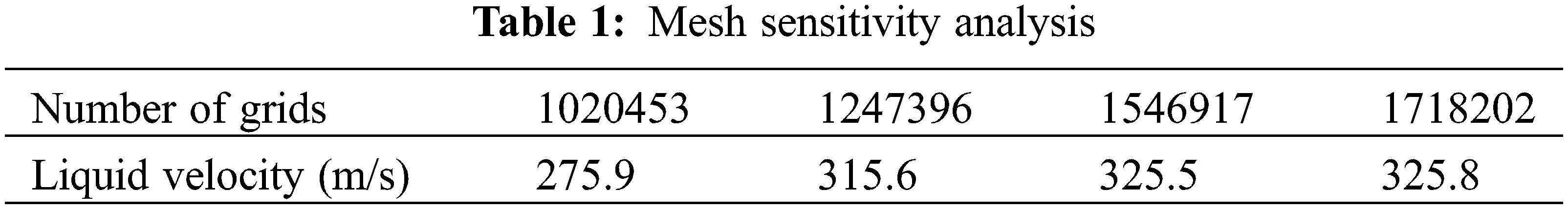
In ANSYS Fluent software (2020 R2), two phases are set for the spray flow field. The first phase is the gas phase, representing the air in the spray flow field, and the second phase is the liquid phase, representing the paint droplets in the flow field. In the experiment, the density of the waterborne coating is 1200 kg/m3, and the viscosity is 94.27 mpa·s measured by the viscometer. The measured experimental data is inputted into the numerical simulation to obtain a more consistent result with the physical experiment. As shown in Fig. 3.
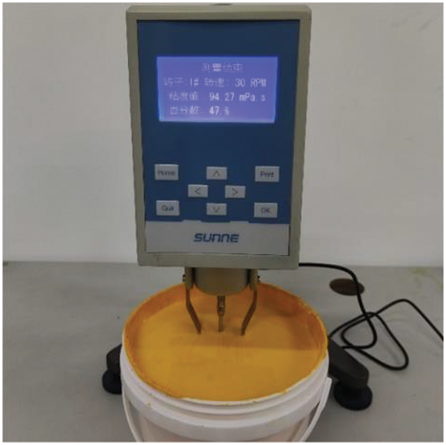
Figure 3: Paint viscometer
The setting of initial conditions and boundary conditions: The coating hole is set as the Mass-Flow Inlet, the mass flow rate of the gas phase is 5 × 10⁻⁶ kg/s, the mass flow rate of the liquid phase is 1.32 × 10⁻³ kg/s, the initial velocity of the liquid phase is 5 m/s, the volume fraction of the liquid phase at the inlet is 0.2, the Turbulence Intensity is 15%, and the Hydraulic Diameter is 2 mm. The central atomization hole and auxiliary atomization hole are set as the Pressure Inlet, and the Gauge Total Pressure of the spray gun is 140 kpa. As the spatial distribution of the spray gun coating is required to be conical, the fan control holes are not set in this simulation and experiment. Gravity is 9.81 m/s, the operating pressure is 1 atm, and the static spraying time is set as 0.3 s.
In order to obtain better results, the setting of the solver is also important. The literature [26] compares the effects of different numerical methods on the results. In this paper, SIMPLE algorithm is used to solve the pressure-velocity coupling. For the unstructured grid, the gradient method of Least Squares Cell-Based is used to lower the calculation cost, and the default interpolation scheme (Second Order) is used for the pressure term. The other discrete schemes are the Second Order Upwind scheme.
3.1 Flow Field Morphology of Spray
Since liquid particles are atomized and transported by high-pressure air and then deposited on the surface of the workpiece, the spray film formation law can be analyzed according to the flow field morphology of the spray. To establish the spraying coordinate system as required, the center point of the spray gun coating hole is the coordinate origin, the Z-axis is the axial direction of the spray cone, and the X- and Y-axes are the circumferential and axial directions of the cylinder respectively. By changing the spray height, spray angle, and cylinder diameter, the static spray flow field in the axial and circumferential directions changes. Fig. 4 shows the cloud diagram of the cylindrical surface spray speed.
Figure 4: Cloud chart of the velocity of the liquid phase on a cylindrical surface with changing position and attitude
To further analyze the velocity of the liquid spray, the transverse velocity distribution of spray on the cylindrical wall in the computational domain is studied here. The influence of one or other factors on the liquid-phase velocity in the spray flow field was studied by fixing three factors, namely spraying height, spraying angle, and cylinder diameter, respectively. In Fig. 5, x and y represent the distance of the cylinder from the spraying center in the circumferential and axial directions, respectively. When the spraying height, spraying angle, and cylindrical diameter change, the transverse velocity of the liquid phase in the spray flow field also changes. With the increase of spraying height and spraying angle, the transverse velocity of the liquid phase when reaching the wall decreases, because the change of the spray gun height and angle will affect the axial distance between the spray gun and the cylindrical wall. For cylindrical circumferential spraying, the spray flow field is greatly affected by the cylindrical diameter and shape, while the axial spraying is similar to plane spraying, and the change of cylindrical diameter does not affect the change of the spray flow field.
Figure 5: Lateral liquid velocity distribution in the spray flow field
3.2 Film Thickness Distribution
Driven by the spray flow field, the paint droplets hit and adhered to the cylindrical wall to form a liquid film. To clarify the influence of the spray gun position and cylindrical diameter on the film thickness distribution, the film formation process can be more intuitively understood by studying the liquid-phase velocity near the cylinder wall, as shown in Fig. 6.
Figure 6: Vector diagram of the liquid-phase velocity near the cylindrical wall
To further study the influence of the position and attitude of the spray gun and the diameter of the cylindrical on the film thickness distribution, the control variable method is used to obtain the corresponding film thickness distribution, as shown in Fig. 7.
Figure 7: Film thickness distribution diagram
The maximum film thickness decreases with the increase of spraying height and angle. When the cylindrical diameter changes, the maximum film thickness does not change. Under the same spraying environment, the increase in spraying height and angle means that the linear distance between the spray gun and the spraying center point is increased, and the speed of liquid particles reaching the cylindrical wall is reduced, which leads to the reduction of the maximum film thickness. Compared with axial spraying, circumferential spraying is greatly affected by the cylindrical surface. With the distance away from the spraying center, the film thickness will be affected by the cylindrical diameter.
3.3 The Joint Effects of Gun Position and Attitude and Cylinder Diameter on Film Thickness Distribution
As discussed earlier, the spraying height, spraying angle and cylinder diameter will affect the film thickness distribution. Through static spraying experiments, it is found that a too low maximum film thickness in the film distribution curve will lead to poor leveling, and a too large maximum film thickness will lead to sagging on the workpiece surface, both of which will affect the film quality. Considering the viscosity of the coating used in the experiment, to ensure the film quality, the maximum film thickness is set at 20–50 μm, and from the obtained numerical simulation results, it is found that the range for adjustment of spraying height is 200–300 mm. The gray prediction and fitting interpolation methods can be used to obtain the range for adjustment of spraying angle within the target range of film thickness, as shown in Fig. 8. By analyzing the change rule of the spraying angle of cylinders with different diameters at different spraying heights in Fig. 8, the changing relationship with the position and attitude of the spray gun within the maximum film thickness range shown in Fig. 9 can be obtained. The larger the diameter of the cylindrical, the larger the adjustable range of the spray gun position and attitude.
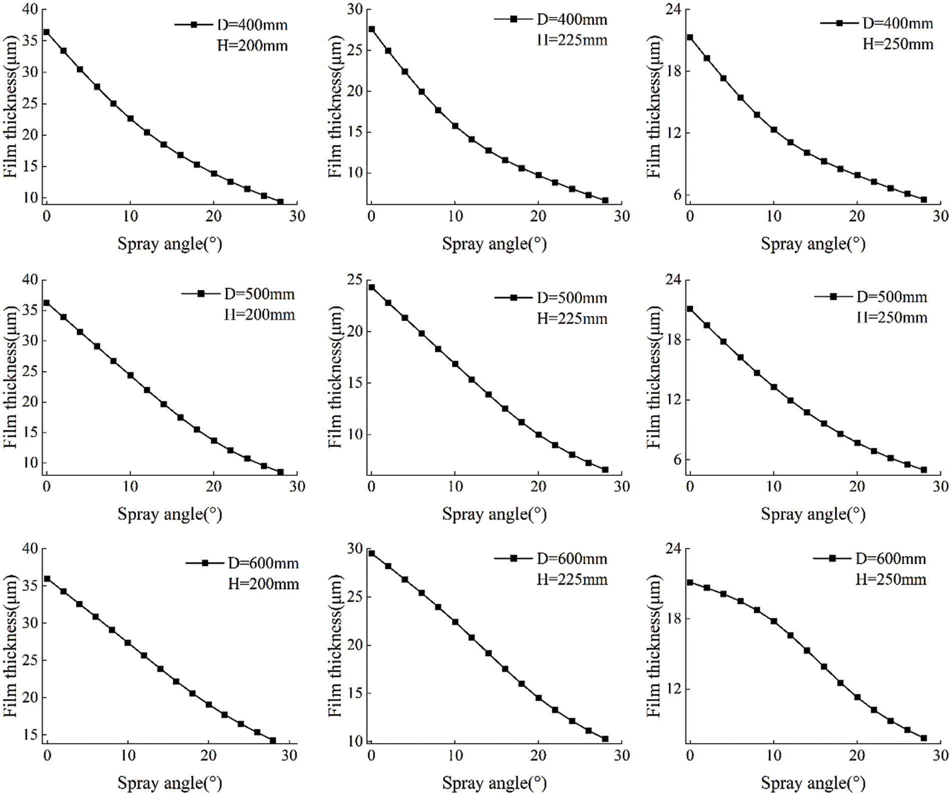
Figure 8: Relation curve between spraying angle and film thickness
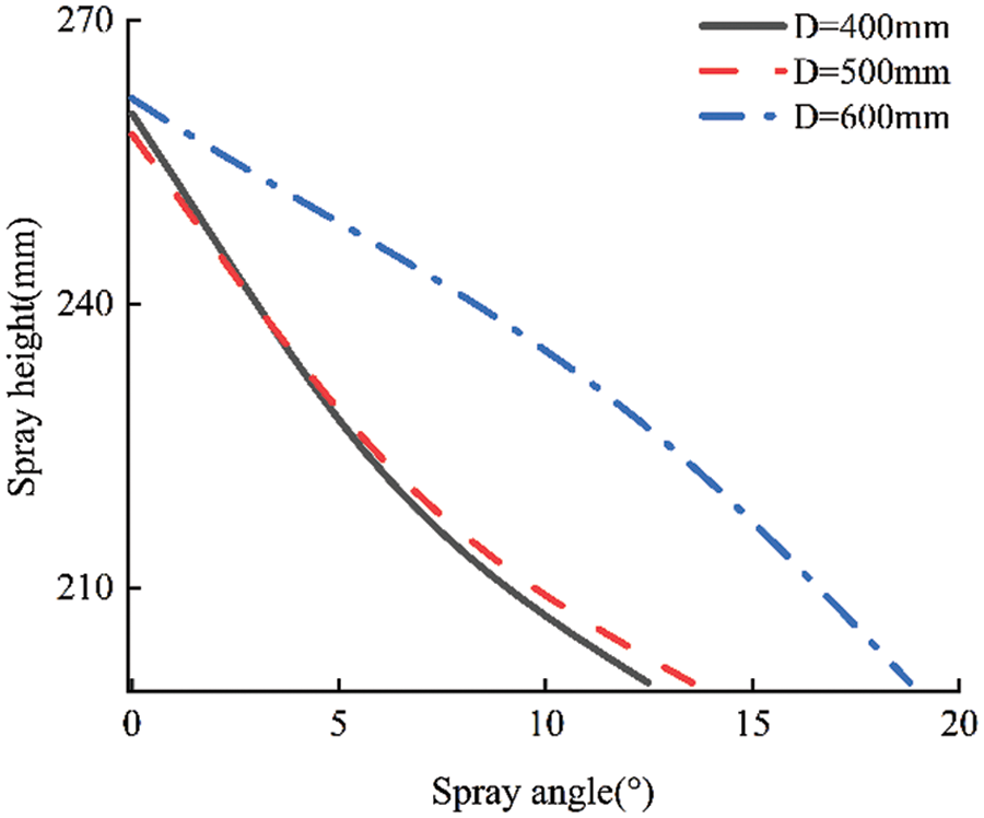
Figure 9: Position and attitude prediction curve of the spray gun
4 Prediction Method of Coating Thickness Distribution in Static Posture Changing Spraying
4.1 Mathematical Model of Film Thickness Distribution
Establishing the mathematical model of the spray gun is the basis of studying the prediction model of the film thickness distribution of variable attitude spraying. Currently, the commonly used models are the β Distribution model [27], analytical sedimentation model [28], parabola model [29], and elliptical double β Distribution models [30]. These models are only used for specific spray guns, and the fitting accuracy is not high. Therefore, a Gaussian sum model with higher fitting accuracy and wider application scope is proposed. The Gaussian sum model [31] is used here to establish the mathematical model of the film thickness distribution.
Assuming that the spraying process parameters and the spraying environment are constant during the static spraying process, the cylindrical surface spraying diagram is shown in Fig. 10. Point S is any point in the spraying area, r is the distance from the spraying center point of the spray gun to point S, R is the spraying radius, θ is the angle between the connecting line of point S and the spray gun and the center line of the spray gun, φ is the angle of the spray gun, α is the spraying angle of the spray gun. When spraying vertically, α = 0°.
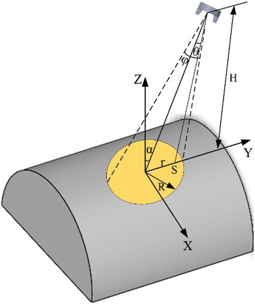
Figure 10: Schematic diagram of cylindrical surface spraying
When the spray gun sprays vertically on the plane, the Gaussian sum model is established, and its expression is as follows:
where ωi, ri, σi is the parameter to be identified, i = 1, 2, ..., N. When N tends to infinity, the function can approximate any form of distribution. However, with the increase of N, the complexity of the model also increases dramatically. In this study, the sum of three Gaussian kernels is used for modeling.
As shown in Fig. 11, arbitrarily selecting a point S within the spraying range, the plane P1 is the reference plane, and the plane P2 parallel to P1 and passing through point S is the working plane. The circular areas C1 and C2 sprayed by the spray gun in the vertical spraying direction intersect P1 and P2, and H and HS are the heights perpendicular to the spraying planes P1 and P2, respectively. According to the differential geometric area amplification theorem:
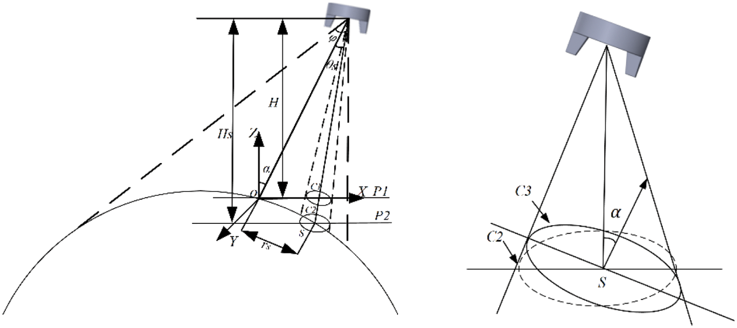
Figure 11: Schematic diagram of cylindrical surface spraying calculation
As the total amount of coating remains unchanged, the relationship between the coating thickness on C1 and C2 can be seen as follows:
Assume that a circular area C3 intersects point S in the spraying plane and the included angle between it and C2 is α, as shown in Fig. 11. Then the coating thickness of the C3 area is:
To sum up, the cylindrical surface spraying model with variable posture is:
In the formula:
4.2 Prediction of Film Thickness Distribution Model
The data points of film thickness are collected through the numerical simulation experiment on the pose change of different cylindrical diameters when spraying at different heights and angles. The parameters to be identified are solved by using the Trust Region algorithm in the MATLAB fitting tool to obtain the parameters to be solved in the corresponding film thickness distribution model when the cylinders with different diameters change their positions and attitude when spraying, as shown in Tables 2–4.
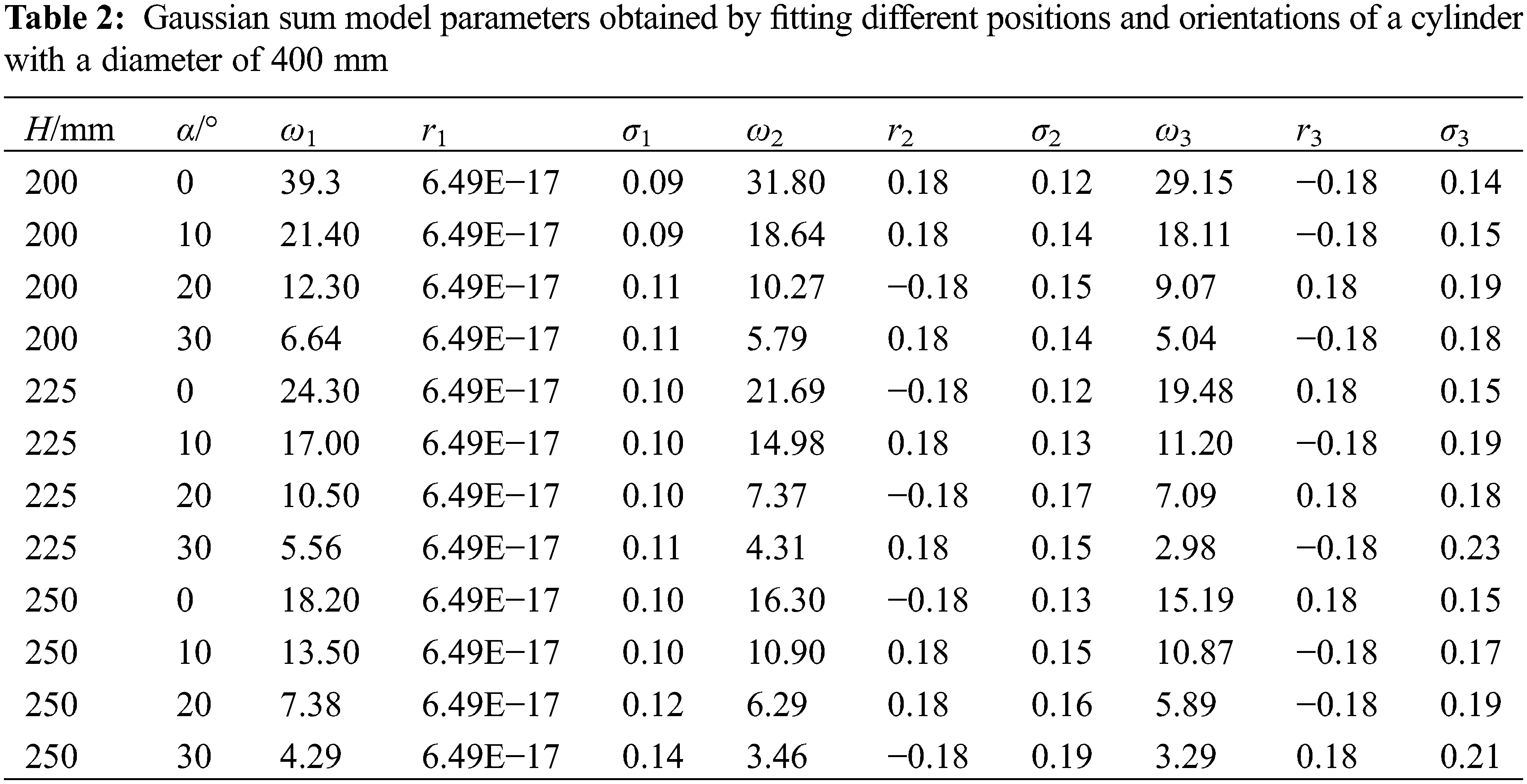
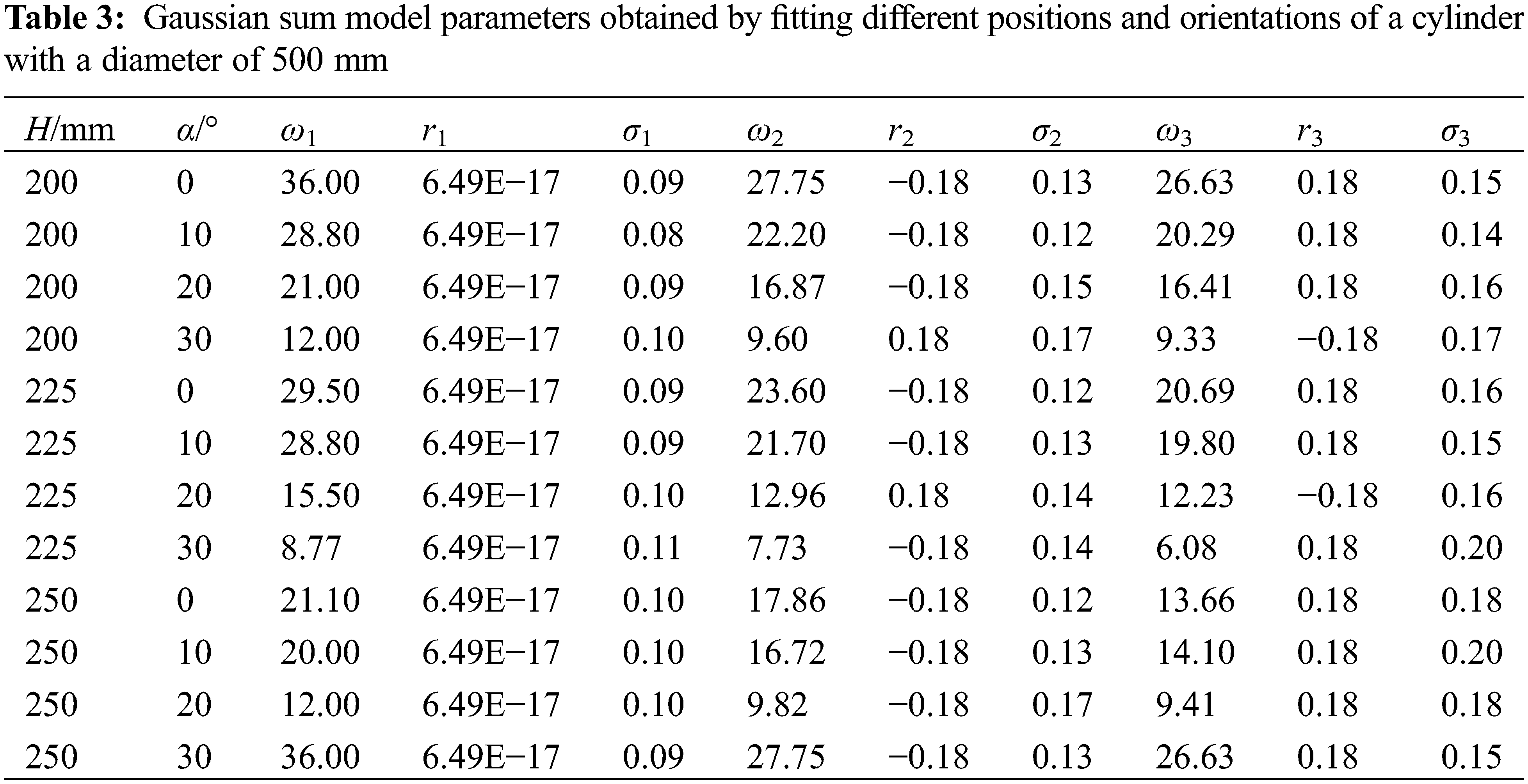
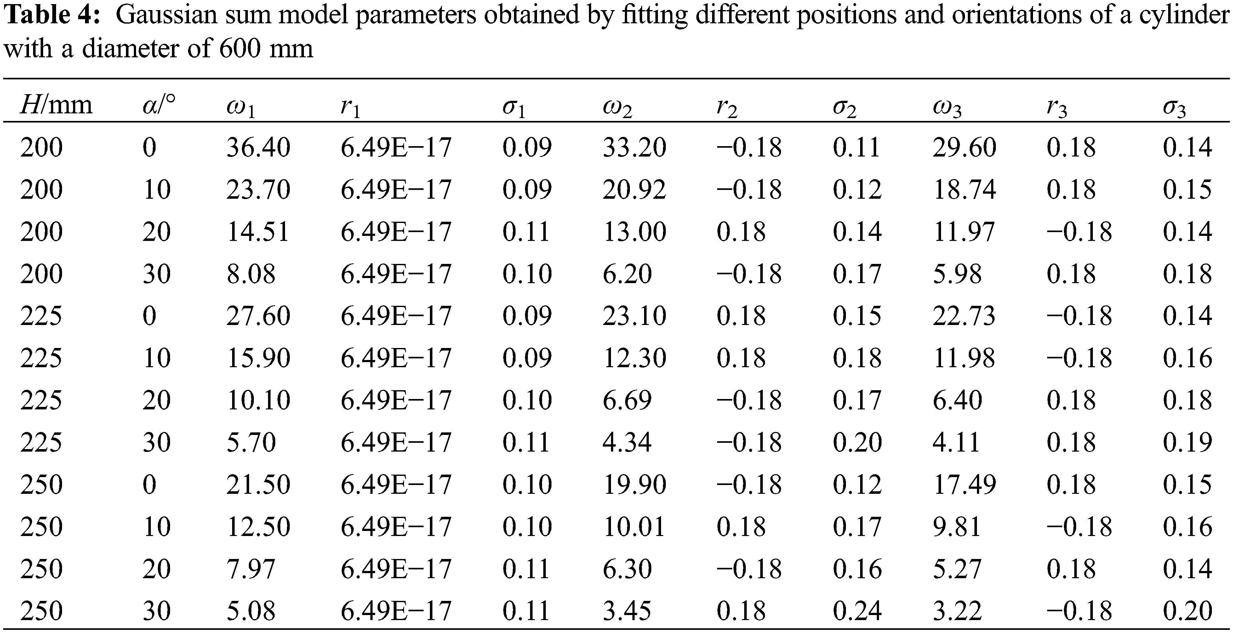
Comparing the coefficients obtained from the fitting, it can be found that some of the data are obviously different, and some are relatively similar. Here, we need to analyze the rules separately. Due to parameters σ1, σ2, and σ3 without obvious change rule, take the average value. while the parameters r2 and r3 are opposite to each other. It can be seen from Tables 2–4 that the parameters ω1, ω2, and ω3 have apparent laws to follow. Under the same spray gun position and posture, there is a decreasing trend with the spray gun position and posture and the cylinder diameter as independent variables, ω1, ω2, ω3. Carrying out a multiple linear regression analysis for the dependent variables, and we obtained the prediction functions of Eqs. (19)–(21) to predict ω1, ω2, ω3. Combined with Eq. (16), the film thickness distribution prediction model can be obtained when different diameter cylinders are sprayed in different positions.
In the formula: Z1 = 58.375, A1 = 0.021, B1 = −0.184, C1 = −0.716
In the formula: Z2 = 50.123, A2 = 0.014, B2 = −0.15, C2 = −0.615
In the formula: Z3 = 48.241, A3 = 0.011, B3 = −0.145, C3 = −0.555
5 Experiment of Robot Static Posture-Changing Spraying
To verify the validity of the simulation model, a robot spraying experimental platform was built to carry out static posture-changing spraying experiments to prove it. Yantian air spray gun was selected for the investigation. The experimental spraying platform comprises an IRB1200 spraying robot, MC-3000 series coating thickness gauge, pneumatic diaphragm pump, air compressor, filter, pressure regulating valve, etc., as shown in Fig. 12. Commercial water-based paint is selected as the paint, a kind of paint using water as the solvent or dispersion medium. Its density and viscosity are consistent with the simulation input parameters. To study and verify the simulation results, cylindrical surfaces with diameters of 400, 500, and 600 mm were used for spraying experiments. In the experiment, the spray gun was randomly set to a height of 205 mm, and an angle of 8°, with the workpiece not touching the paint film within 2 days after spraying. After the coating was completely cured, a coating thickness gauge was used to measure the thickness of the paint film in X and Y directions, and the cylindrical surface development coordinate system coordinates of this point and the film thickness were recorded. When measuring the film thickness, the measurements were taken in triplicate for every 5 mm of the film in the chosen direction. The average value was taken as the film thickness of each measured point.
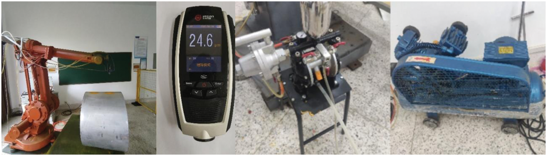
Figure 12: Experimental platform
As the simulation provides results in wet film thickness, the wet film thickness needs to be converted to dry film thickness to obtain a more realistic comparison. The conversion formula is as follows [32]:
In the formula, T2 is the simulated dry film thickness, T1 is the simulated wet film thickness, and VS is the volume of solid content.
The comparison between the experimental and simulated spraying results is shown in Fig. 13. The simulation results are consistent with the experimental results regarding film distribution shape. The errors between the simulation data and the experimental data may be related to many factors, such as the spraying environment (temperature and humidity), the accuracy of measuring instruments (paint viscometer, film thickness gauge), and the film flow. The mean square deviation of the film thickness distribution obtained from the simulation and experiment of X and Y direction spraying for cylinder diameters of 400, 500, and 600 mm are 7.37 and 6.78, 7.47 and 7.79, and 8.65 and 8.22, respectively. The comparison between the simulation and experimental data is shown in Fig. 14. It is obvious that the film thickness distribution obtained from the robot spraying experiment and simulation is consistent.
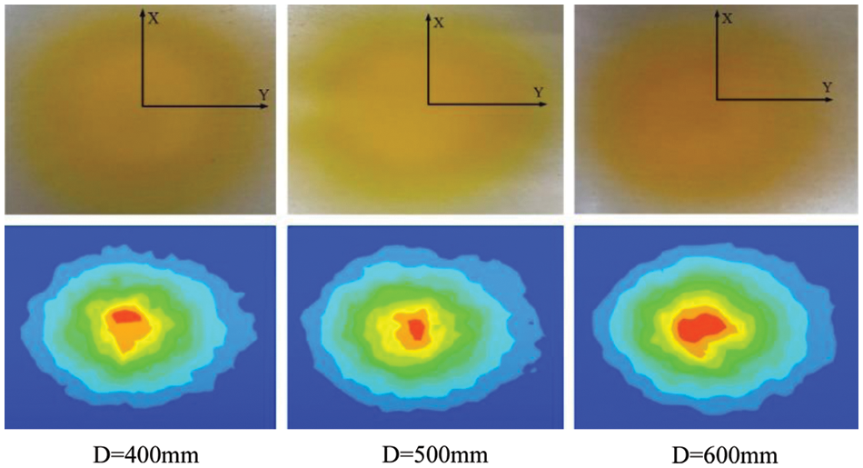
Figure 13: Comparison of the spraying results
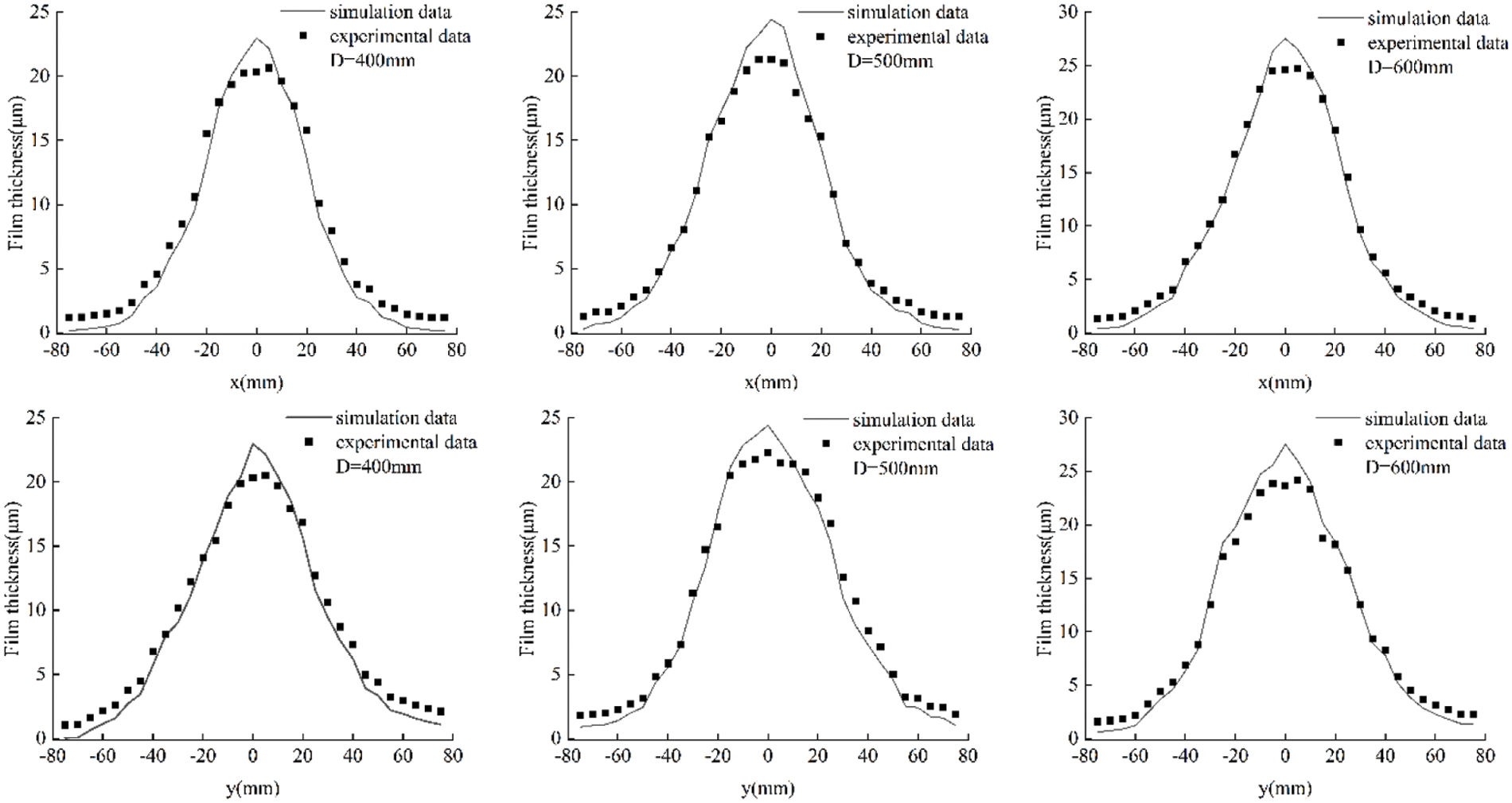
Figure 14: Comparisons of the simulation and experiment data
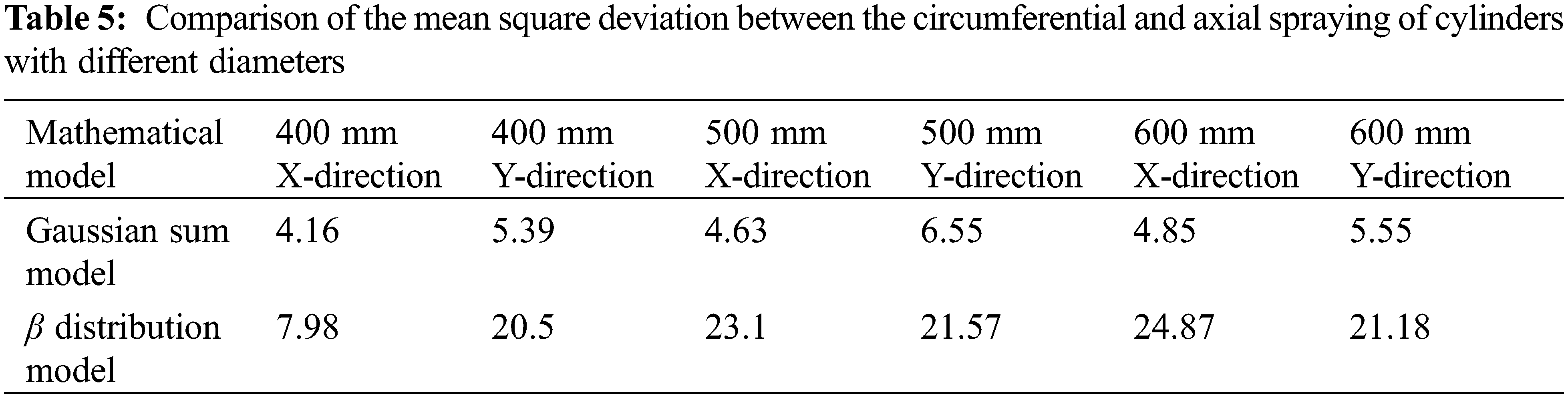
To verify the feasibility of the prediction method, the film thickness distribution prediction method of the β distribution model is compared with the previously described prediction method, as shown in Fig. 15. The comparison of the film thickness mean square deviation of the circular and axial sprayed cylinders with different diameters under the two methods is presented in Table 5.
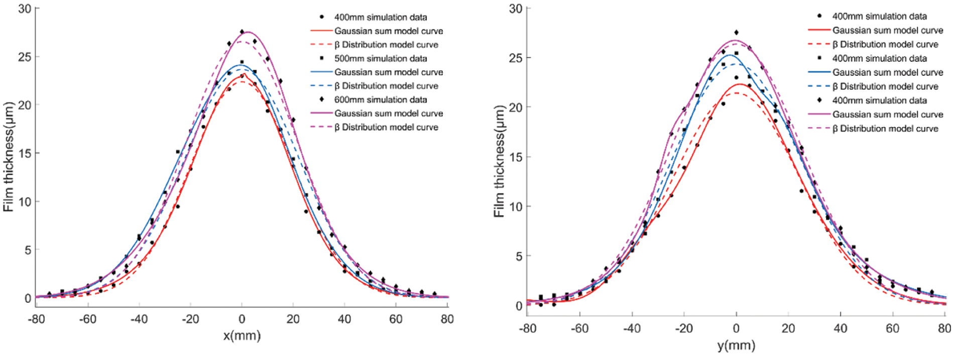
Figure 15: Comparison of the film thickness prediction fitting diagrams
6 Conclusion and Future Prospects
In this paper, CFD theory is used to study the film forming characteristics of cylindrical with different diameters by changing the position and orientation of the spray gun. The results of the numerical simulation show that changes in the position and attitude of the spray gun and the diameter of the cylinder will change the liquid phase velocity when the paint reaches the cylindrical surface and cause a large change in the film thickness, due to the position and attitude of the spray gun.
A comparison of the obtained results show that the CFD simulation results are in good agreement with the experimental results, so the established CFD simulation model of the cylindrical surface static posture-changing spraying is effective. Compared to the β Distribution model, the Gaussian sum model of cylindrical surface change position and attitude of spray film thickness distribution prediction model has a better fitting accuracy.
Although the CFD numerical simulation method is used to study the film-forming process of aerial spraying, it can intuitively and effectively simulate the spray flow field shape and film thickness distribution, greatly reducing the challenge of spraying cost and uncertainty factors. However, the film thickness obtained from the numerical simulation results only represents the wet film thickness and does not consider the change in film thickness distribution caused by wet film leveling. In view of the above problems, in future research, in order to more realistically simulate the leveling process of wet film on the cylindrical surface under actual conditions, it should be considered when building the simulation model.
Acknowledgement: We would like to thank the reviewer for the many useful comments.
Funding Statement: This work was supported in part by the National Natural Science Foundation of China (51405418); in part by the Major Program of Natural Science Foundation of Colleges and Universities in Jiangsu Province (18KJA460009); in part by the Jiangsu “Qing Lan Project” Talent Project (2021); Major Projects of Natural Science Research in Jiangsu Higher Education Institutions (Grant No. 21KJA460009); and General Program of Jiangsu University Natural Science Foundation (22KJD460009).
Conflicts of Interest: The authors declare that they have no conflicts of interest to report regarding the present study.
References
1. Abubakar, A. A., Arif, A. F. M., Al-Athel, K. S., Akhtar, S. S. (2017). Modeling residual stress development in thermal spray coatings: Current status and way forward. Journal of Thermal Spray Technology, 26(6), 1115–1145. [Google Scholar]
2. Sahir Arıkan, M. A., Balkan, T. (2000). Process modeling, simulation, and paint thickness measurement for robotic spray painting. Journal of Robotic Systems, 17, 479–494. [Google Scholar]
3. Ye, Q., Pulli, K. (2017). Numerical and experimental investigation on the spray coating process using a pneumatic atomizer: Influences of operating conditions and target geometries. Coatings, 7(1), 13. [Google Scholar]
4. Wang, Y. A., Xie, X. P., Lu, X. H. (2020). Design of a double-nozzle air spray gun and numerical research in the interference spray flow field. Coatings, 10(5), 475. [Google Scholar]
5. Liu, Y., Zeng, Y., Zhao, X., Liu, J., Liu, D. (2021). Analysis of film forming law and characteristics for an air static spray with a variable position of the plane. Coatings, 11(10), 1236. [Google Scholar]
6. Conner, D. C., Greenfield, A., Atkar, P. N., Rizzi, A. A., Choset, H. (2005). Paint deposition modeling for trajectory planning on automotive surfaces. IEEE Transactions on Automation Science and Engineering, 2(4), 381–392. [Google Scholar]
7. Zhao, P. (2017). Study on deposition thickness model of robot electrostatic air spraying under multi field coupling (Master Thesis). Lanzhou, China: Lanzhou University of Technology. [Google Scholar]
8. Zhang, S. Z., Mao, W., Zhen, J. B., Li, C. L. (2019). Research progress of electrostatic spraying coating thickness distribution model. Surface Technology, 48(1), 291–297. [Google Scholar]
9. Fogliati, M., Fontana, D., Garbero, M., Vanni, M., Baldi, R. et al. (2006). CFD simulation of paint deposition in an air spray process. Journal of Coatings Technology and Research, 3(2), 117–126. [Google Scholar]
10. Barry, M., Farhad, N., Vahid, A. (2017). Sensitivity analysis of spray painting process to input parameters: Validation of CFD jet impingement model against an experimental dataset. Robotics and Computer-Integrated Manufacturing, 47, 11–16. [Google Scholar]
11. Garbero, M., Vanni, M., Baldi, G. (2002). CFD modeling of a spray deposition process of paint. Macromolecular Symposia, 187(1), 719–730. [Google Scholar]
12. Tafuri, S., Ekstedt, F., Carlson, J. S., Mark, A., Edelvik, F. (2012). Improved spray paint thickness calculation from simulated droplets using density estimation. ASME 2012 International Design Engineering Technical Conferences & Computers and Information in Engineering Conference, vol. 2, pp. 339–347. USA: Chicago, Illinois. [Google Scholar]
13. Chen, Y., Chen, S., Chen, W., Hu, J., Jiang, J. (2021). An atomization model of air spraying using the volume-of-fluid method and large eddy simulation. Coatings, 11(11), 1400. [Google Scholar]
14. Sanjosé, M., Senoner, J. M., Jaegle, F., Cuenot, B., Moreau, S. et al. (2011). Fuel injection model for Euler-Euler and Euler-Lagrange large-eddy simulations of an evaporating spray inside an aeronautical combustor. International Journal of Multiphase Flow, 37(5), 514–529. [Google Scholar]
15. Kaltenbach, C., Laurien, E. (2018). CFD simulation of spray cooling in the model containment THAI. Nuclear Engineering and Design, 328, 359–371. [Google Scholar]
16. Singh, S. K., Ali, B. A. (2021). Computational investigation of air solid flow in a spray dryer for effluent treatment. Journal of the Indian Chemical Society, 97(7), 1142–1145. [Google Scholar]
17. Chen, W. Z., Chen, Y., Zhang, W. M., He, S. W., Li, B. et al. (2019). Paint thickness simulation for robotic painting of curved surfaces based on Euler-Euler approach. Journal of the Brazilian Society of Mechanical Sciences and Engineering, 41(4), 199. [Google Scholar]
18. Chen, Y., Hu, J., Zhang, G., Chen, W. Z., Pan, H. W. et al. (2019). Study on film forming characteristics of spherical surface spraying. Journal of Hunan University (Natural Science Edition), 46(6), 37–46. [Google Scholar]
19. Scheer, I. W., Beaumont, C. (2011). A new quality methodology and metrics for spray pattern analysis. Atomization and Sprays, 21(3), 189–202. [Google Scholar]
20. Zhao, B. S., Nagisa, S., Keiya, N., Youichi, O., Min, G. (2018). Experimental study on impingement spray and near-field spray characteristics under high-pressure cross-flow conditions. Fuel, 218(1), 12–22. [Google Scholar]
21. Chen, W., Li, X., Ge, H., Wang, L., Zhang, Y. (2020). Trajectory planning for spray painting robot based on point cloud slicing technique. Electronics, 9(6), 908. [Google Scholar]
22. Zeng, Y., Yu, Y., Zhao, X., Liu, Y., Liu, J. et al. (2021). Trajectory planning of spray gun with variable posture for irregular plane based on boundary constraint. IEEE Access, 9, 52902–52912. [Google Scholar]
23. Jubare, H., Dai, R., Ruslim, E., Mansouri, S., Shan, Z. et al. (2019). New perspectives on capturing particle agglomerates in CFD modeling of spray dryers. Drying Technology, 38(5–6), 685–694. [Google Scholar]
24. Kampen, A. V., Kohlus, R. (2017). Systematic process optimisation of fluid bed coating. Powder Technology, 305, 426–432. [Google Scholar]
25. Guan, L. W., Chen, L. (2019). Trajectory planning method based on transitional segment optimization of spray painting robot on complex-free surface. Industrial Robot the International Journal of Robotics Research and Application, 46(1), 31–43. [Google Scholar]
26. Langer-Moller, A., Lowe, J., Kessler, R. (2017). Investigation of the NREL phase VI experiment with the incompressible CFD solver THETA. Wind Energy, 20(9), 1529–1549. [Google Scholar]
27. Arikan, M. A. S., Balkan, T. (2000). Process modeling, simulation, and paint thickness measurement for ro-botic spray painting. Journal of Robotic Systems, 17(9), 479–494. [Google Scholar]
28. Li, H., Xi, X. S. (2015). Sedimentary fans: A new genetic model for sedimentary exhalative ore deposits. Ore Geology Reviews, 65, 375–389. [Google Scholar]
29. Balkan, T., Arikan, M. A. S. (2021). Surface and process modeling and off-line programming for robotic spray painting of curved surface. Journal of Robotic Systems, 1, 455–465. [Google Scholar]
30. Zhang, Y. G., Huang, Y. M., Gao, F., Wang, W. (2006). A new model of air spray gun for painting robot. Journal of Mechanical Engineering, 11, 226–233. [Google Scholar]
31. Zhou, B., Shao, Z. H., Meng, Z. D., Dai, X. Z. (2013). Modeling of coating growth rate of spray robot based on gaussian sum model. Journal of Huazhong University of Science and Technology (Natural Science Edition), 41(S1), 463–466. [Google Scholar]
32. Goldschmidt, A., Steitberger, H. J. (2007). Basf handbook on basics of coating technology. Hannover, Germany: Vincentz Network. [Google Scholar]
Cite This Article
 Copyright © 2023 The Author(s). Published by Tech Science Press.
This work is licensed under a Creative Commons Attribution 4.0 International License , which permits unrestricted use, distribution, and reproduction in any medium, provided the original work is properly cited.
 Downloads
 Citation Tools