
 Submit a Paper
 Propose a Special lssue
 Open Access
ARTICLE

Simulation and Optimization of the Fluid Solidification Process in Brazed Plate Heat Exchangers
1 College of Energy and Mechanical Engineering, Shanghai University of Electric Power, Shanghai, 201306, China
2 CGN New Energy Holdings Co., Ltd., Shanghai Branch, Shanghai, 200241, China
* Corresponding Authors: Weiting Jiang. Email: ; Lei Zhao. Email:
(This article belongs to the Special Issue: CFD Modeling and Multiphase Flows)
Fluid Dynamics & Materials Processing 2023, 19(10), 2597-2611. https://doi.org/10.32604/fdmp.2023.027504
Received 01 November 2022; Accepted 14 March 2023; Issue published 25 June 2023
 View Full Text
 Download PDF
Abstract
When a brazed plate heat exchanger is used as an evaporator, the working mass in the channel may undergo solidification, thereby hindering the refrigeration cycle. In this study the liquid solidification process and its optimization in a brazed plate heat exchanger are investigated numerically for different inlet velocities; moreover, different levels of corrugation are considered. The results indicate that solidification first occurs around the contacts, followed by the area behind the contacts. It is also shown that dead flow zones exist in the sharp areas and such areas are prone to liquid solidification. After optimization, the solidification area attains its smallest value when a corrugation spacing λ = 4.2 mm is considered.Keywords
The plate heat exchanger has been fully functional as an effective energy-saving device in industrial production sections such as medical, food, integrated chemical fiber, shipbuilding, engine, metallurgy and chemistry [1]. The fluid flow pattern within a plate heat exchanger is complex and variable, and the plates are stacked and combined in different ways [2]. The brazed plate heat exchanger is composed of multi-layer corrugated plates filled with copper foil between the plates and heated in a vacuum furnace. This creates a fluid channel between the plates, and the two fluids will complete the heat exchange without contact. The welded plate heat exchanger has the advantages of a small footprint, high thermal performance, lightweight, high rigidity, low pressure, high-temperature resistance, high automation, etc. [3]. However, this structure is usually affected by uneven fluid distribution in different channels, especially when used as an evaporator.
Solidification occurs in the channel when the brazed plate heat exchanger is used as an evaporator to prepare cold water. Li et al. [4] and Navarro-Peris et al. [5] believed that the uneven distribution of refrigerants is prone to freezing. If not handled in time, it may cause plate deformation and fracture. In addition, Luan et al. [6] found many impurities in the inlet water, and scaling will occur in the narrow channel, which directly leads to the decrease of fluid velocity in the channel and dramatically increases the possibility of icing. Because the brazed plate heat exchanger is not removable and the degree of visualization is low, it is difficult to solve the problem by experimental method. Therefore, many scholars systematically use numerical simulation to analyze the flow inside the heat exchanger. Gherasim et al. [7] studied a two-channel plate heat exchanger’s flow characteristics and temperature distribution and concluded that the heat transfer performance under mixed convection conditions is better. Cai et al. [8] studied the fluid flow and heat transfer at different velocities through numerical simulations, and the results showed that the distribution area significantly influences the heat exchanger’s performance. Abbas et al. [9] and Gullapalli et al. [10] conducted numerical simulations of the heat transfer performance of the heat exchanger, respectively, and to avoid backflow at the beginning of the flow channel, they both took similar expansion measures in the model building by expanding the inlet and outlet along the length, and the free space at the outlet prevents the sudden accumulation of thermal fluid and solves the problem of temperature anomalies at the outlet in previous simulation results. At the current stage, the antifreeze of brazed plate heat exchangers is divided into refrigerant-side antifreeze and water-side antifreeze. Refrigerant-side antifreeze is mainly focused on controlling evaporative pressure and other aspects, while water-side antifreeze is mainly focused on controlling the inlet and outlet water flow and water temperature and other aspects [11–14]. In practice, most of the brazed plate heat exchangers use the water-side antifreeze method, i.e., to ensure that the average outlet temperature is higher than the freezing point temperature.
It is possible to predict experimentally whether the solidification is occurring inside the plate heat exchanger, but it is not yet possible to obtain the exact location and time of solidification directly. CFD simulation can find in the channel solidification position in the vicinity of the solder joint and the sharp part. To prevent the solidification of the working medium, it should ensure that the sharp part of the plate is as smooth as possible. In this paper, a three-dimensional numerical model of solidification in a single-channel heat exchanger is established. The solidification of the fluid inside the brazed plate heat exchanger is calculated using the solidification melting model and the external UDF method. The simulation flow chart is shown in Fig. 1, and the optimum corrugation spacing is found by comparing multiple sets of data.
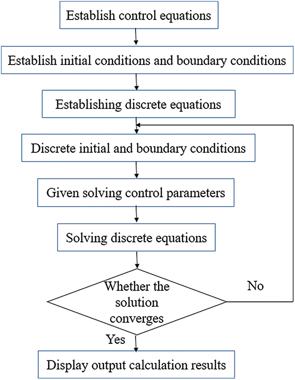
Figure 1: Simulation flow chart
2 Physical and Mathematical Models
The choice of model is an essential prerequisite for numerical simulation. In this paper, we choose a commercial brazed plate heat exchanger for the simulation study, whose model is B3-040-10DQ with a wavelength of 5 mm, corrugation depth of 1 mm, chevron angle is 51° and wave number 38. The numerical simulation mainly studies the solidification heat transfer of the waterside. Due to the symmetry and periodicity of the flow inside the brazed plate heat exchanger, one of the flow channels is selected as the calculation domain to save the calculation time. As shown in Fig. 2, to prevent significant backflow at the inlet and outlet, 10 mm was expanded on the inlet side of the model and 5 mm on the outlet side. In order to facilitate the analysis, the following assumptions are made for the calculated physical model: constant wall temperature, constant ambient temperature, fluid satisfies the Boussinesq approximation, heat transfer in phase change solid and liquid media by heat conduction, ignoring the effect of convection and radiation.
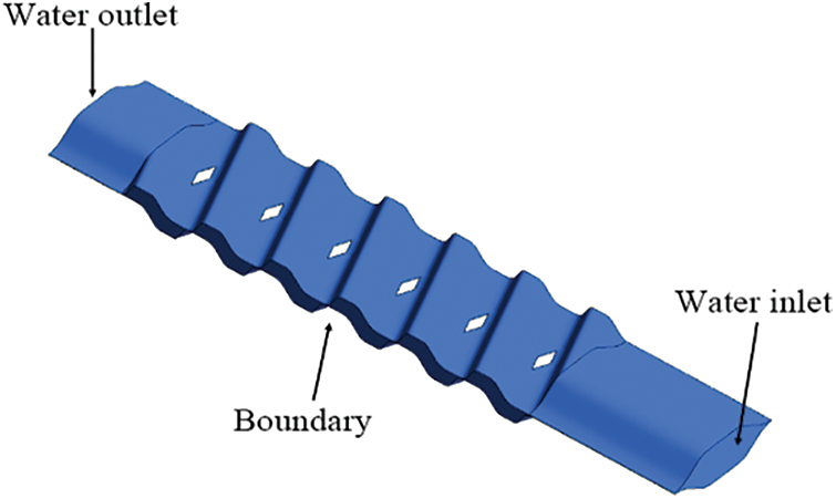
Figure 2: Three-dimensional model (import and export expansion processing)
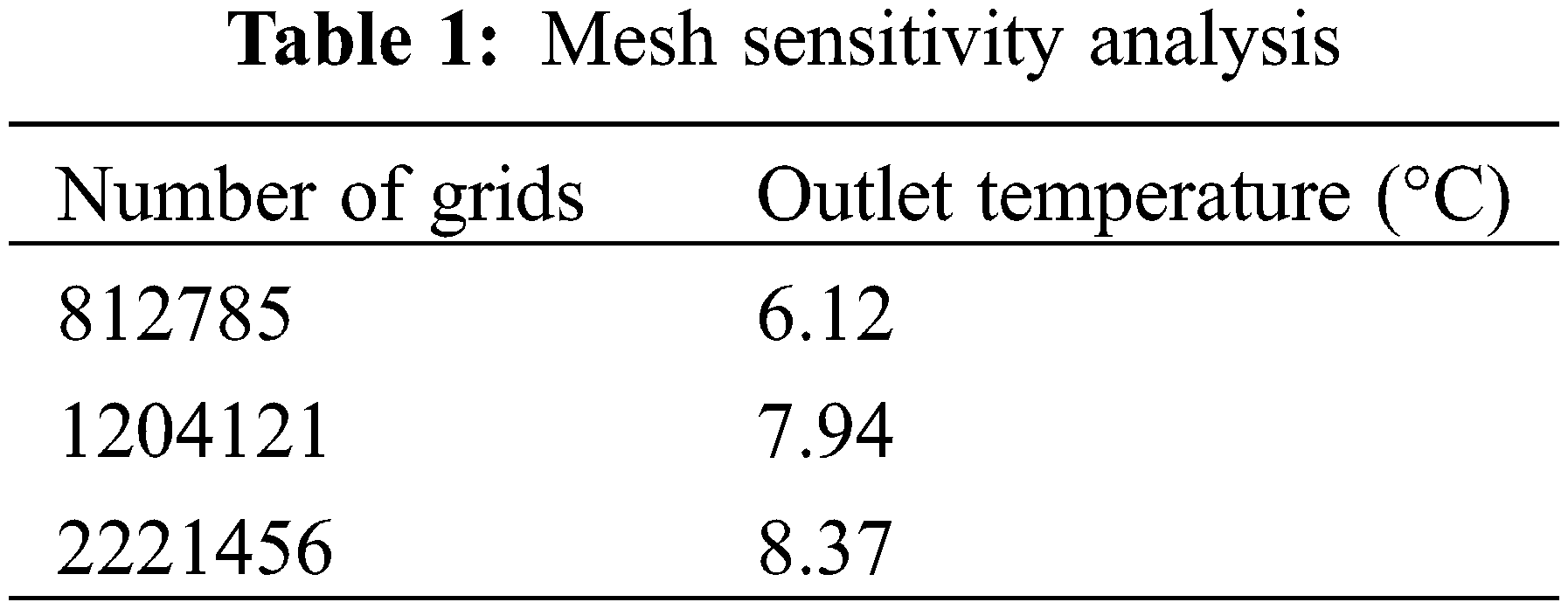
The grid classification method uses the Poly-Hexcore grid classification method based on the Fluent 2020R2 version, as shown in Fig. 3. This classification method can also improve the overall grid quality, reduce the number of grids, and compress the calculation time to a minimum. The sensitivity analysis of the grids is shown in Table 1, which shows the outlet temperature of the model at an inlet temperature of 12°C. The grid numbers for this study’s three options are 812785, 1204121 and 2221456. The variation of the calculation results is minimal when the grid number exceeds 1.2 million. Considering the computational resources, option two is chosen to simulate the whole model. The number of grids in scheme 2 is 1204121.
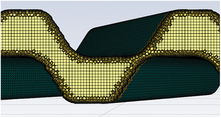
Figure 3: Internal grid division of fluid domain
The enthalpy of a material is calculated as the sum of the sensible enthalpy h and the latent heat ΔH:
where
The liquid phase fraction
Mathematical model when water is the solid phase:
Turbulence model for liquid water [16–18]:
1) Continuous equation:
where
2) Momentum equation:
where
3) Energy equation:
where T is temperature, K;
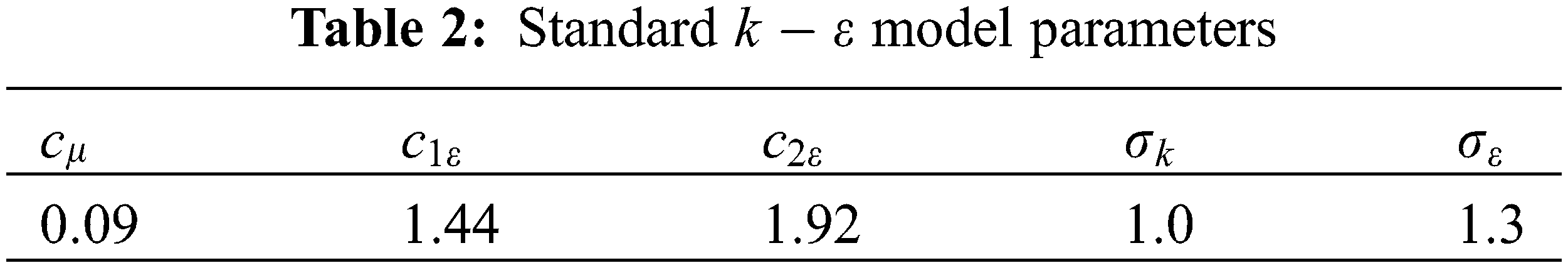
4) Standard
where k is turbulent kinetic energy;
2.3 Selection of Boundary Conditions
The upper and lower surfaces of the fluid domain are defined as fixed temperature,
2.4 Model Accuracy Verification
To verify the correctness of the numerical simulation of the waterside, the physical model of the waterside, as shown in Fig. 2, was established by Solid Works software. According to the experimental data [20], the inlet is set as the velocity inlet, the outlet is set as the pressure outlet, the walls on both sides are set as the period boundary, and the upper and lower walls are fixed temperatures. Fig. 4 shows the relationship between the inlet temperature and the outlet temperature of the waterside. From the figure, it can be seen that the calculated value is slightly in error with the experimental value, but the direction of the temperature is correct, which shows that the calculation method of this numerical simulation is accurate and provides a guarantee for the study of water solidification between the plates.
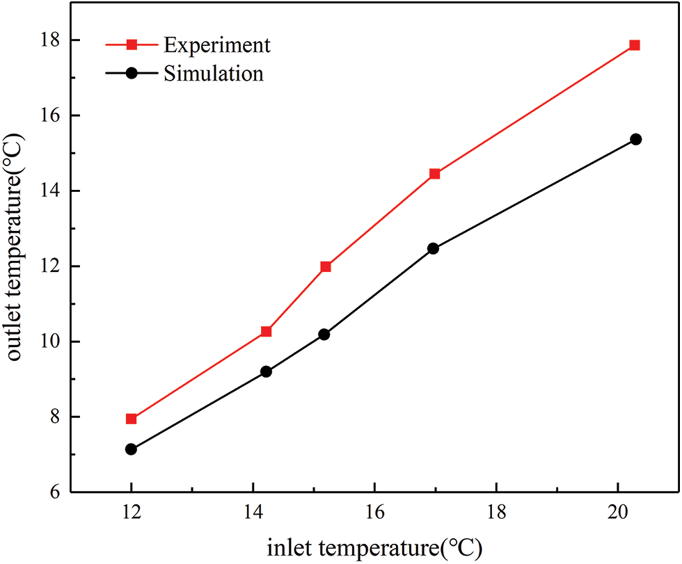
Figure 4: Comparison of inlet and outlet temperature of water side
3 Numerical Simulation Results Analysis
In the process of heat exchange between the refrigerant and circulating water in the evaporator, the evaporation temperature of a specific place will lead to a rapid decrease in the local temperature of the waterside, the circulating water temperature near the surface of the heat exchanger corrugated plate is lower than its phase change temperature, the ice on the surface of the ice nucleus will gather and grow here, after releasing latent heat water will become solid, if the temperature here continues to decrease, this phenomenon will gradually move between the plates, which will lead to the mainstream area solidification, impede the flow of fluid and destroy the shape of the plate. In this section, numerical simulations are performed to study the solidification of the internal fluid at different inlet velocities, the distribution of the mass fraction of the fluid in different sections, and the solidification of the fluid between the plates of different models at the same inlet flow rate.
3.1 Internal Solidification at Different Inlet Velocities
As shown in Fig. 5, the distribution of the liquid mass fraction of the whole calculation domain is shown at the inlet velocity of 0.4 m/s. As can be seen from the figure, the edge position behind the heat exchanger contacts begins to solidify at 20 s. The reason for this is that the contacts have an obstructive effect on the flow of fluid, and the separation of the boundary layer causes the backflow of the fluid behind it, and its flow direction is not consistent with the mainstream direction, which reduces the fluid flow rate and produces solidification. At 60 s, the solidification continues behind the contacts of unit 5 and unit 6 of the calculation domain especially the solidification of unit 6 is the most obvious because the more backward the unit flow and heat exchange is adequate. The solidification at 100 s is approximately the same as that at 60 s, indicating that solidification does not continue at this flow rate.
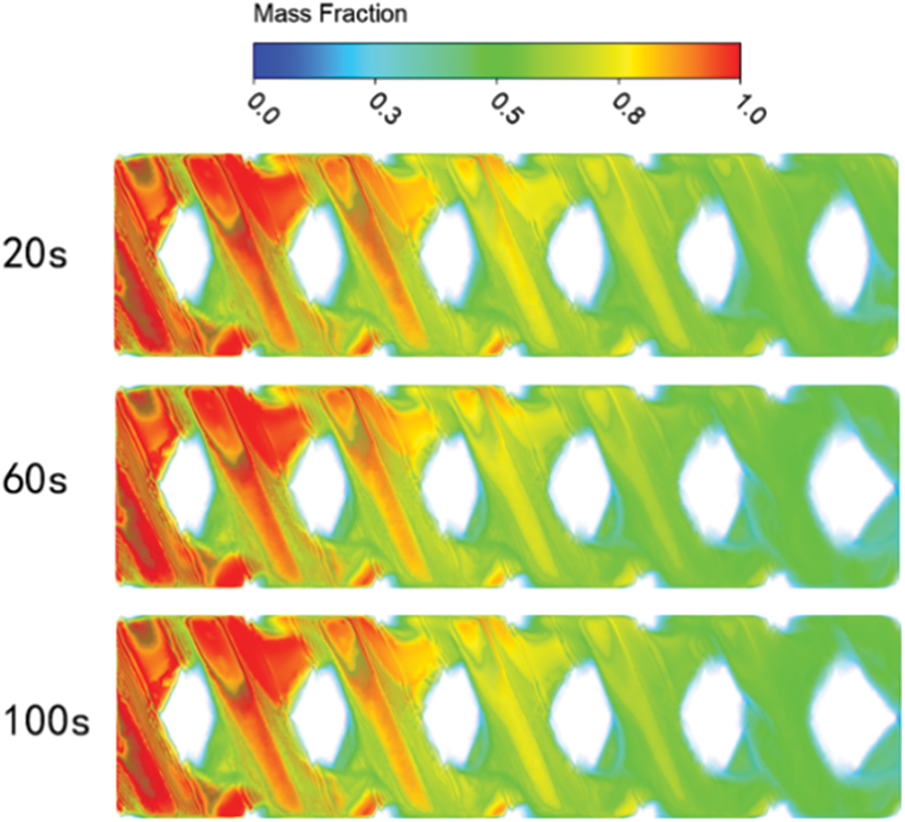
Figure 5: Liquid mass fraction (inlet velocity 0.4 m/s)
To more clearly see the solidification phenomenon between the plates, reduce the inlet flow rate so that the solidification phenomenon develops faster. Fig. 6 shows the distribution of the liquid mass fraction of the whole calculation domain at the inlet velocity of 0.1 m/s. It can be noticed from the diagram that the solidification area around the contacts at 20 s is more significant than that at an inlet velocity of 0.4 m/s. At 60 s, solidification also starts in the mainstream area between the plates. At 100 s, a large solidification area occurred in the mainstream area at unit 5 and unit 6, but it stabilized. This is because the mainstream area water flow rate is higher, the turbulence degree is greater, and the water and the wall convective heat transfer occurs, absorbing cold, but also with the lower flow of water heat exchange, not conducive to the generation of ice nuclei. When the water flow rate is low, the degree of turbulence is minor, the heat exchange with the lower layer of water is reduced, and ice nucleation is likely to occur. Xu et al. also found that an appropriate increase in the heat exchanger inlet flow rate has an abatement effect on the ice layer [21]. It can also be found from the figure that a small area of solidification occurs in the upper and lower regions of the calculation domain, and this location is where the wave crest of the lower plate meets the wave trough of the upper plate, which has a significant pressure change, a considerable resistance to fluid flow, and a low flow rate.
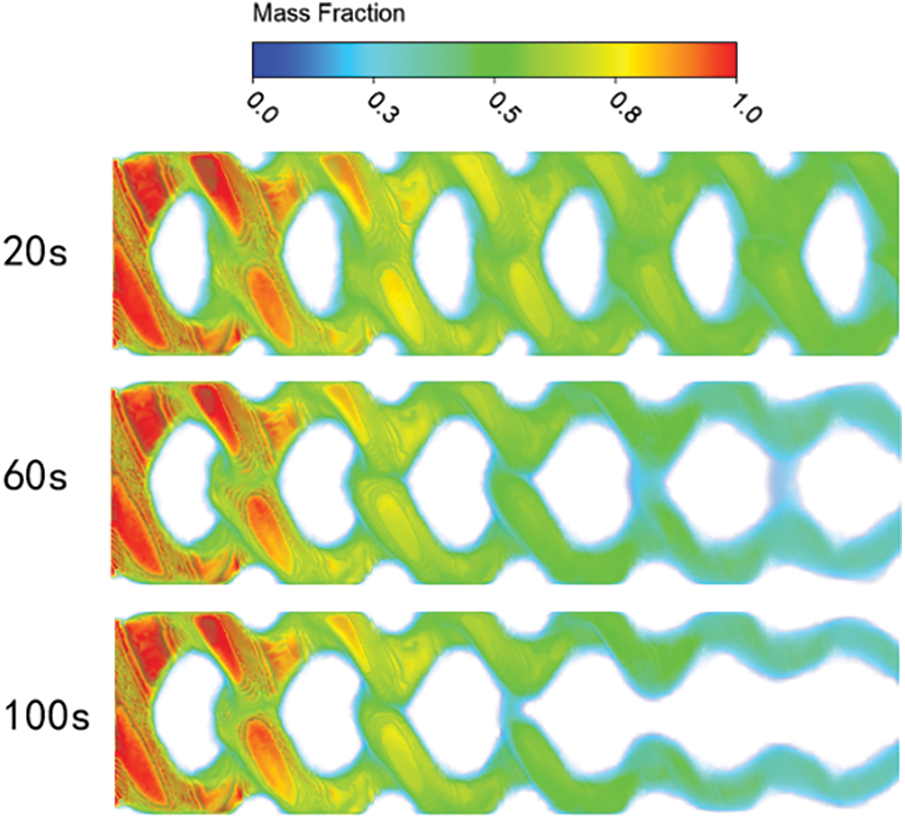
Figure 6: Liquid mass fraction (inlet velocity 0.1 m/s)
3.2 The Solidification of Different Sections in the Calculation Domain
Fig. 7 shows the liquid mass fraction distribution at 50% of the vertical section along the direction of fluid flow. It can be observed from the figure that the circulating water close to the plate began to solidify at 20 s, and the solidification was uniform and distributed around. This is because the fluid near the wall is viscous, resulting in a decrease in its flow rate and a decrease in the degree of turbulence. Although its heat transfer coefficient is reduced, the low flow rate leads to sufficient heat transfer and can absorb more cold. As time passes, the mainstream area continues to solidify. Due to the presence of ice nuclei, the icing will continue until the 5th and 6th units solidify at 100 s.
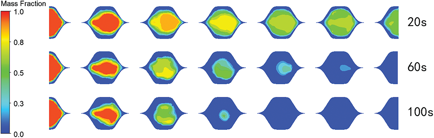
Figure 7: Liquid mass fraction distribution at 50% position of vertical section
Figs. 8 and 9 show the distribution of liquid mass fraction at 30% and 70% vertical sections along the flow direction. From the diagram, we can find that at 20 s, the rear of the intersection position of the two plates first solidified, which is the same as the analysis in 3.1. The pressure change at this position is large, the flow resistance to the fluid is considerable, and the flow rate is low, so the solidification phenomenon occurs fastest. With the change of time, the upper plate’s peak position and the lower plate’s trough position solidify because the heat transfer coefficient at this position is more significant. The solidification is the same at 30% and 70% of the vertical section, but the position is opposite, determined by the unique structure of the heat exchanger plate.
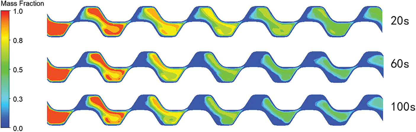
Figure 8: Liquid mass fraction distribution at 30% position of vertical section
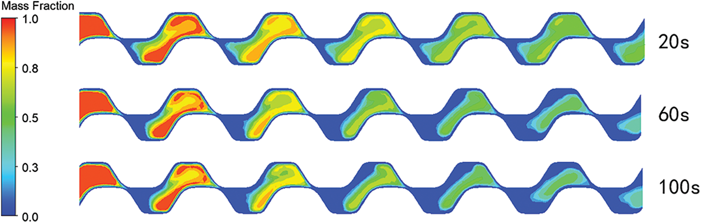
Figure 9: Liquid mass fraction distribution at 70% position of vertical section
3.3 Effect of Different Types of Plates on Solidification
The solidification simulation of two different commercial plate heat exchangers was carried out, and the models were B3-040-10 DQ and B3-045-10 DQ, respectively. The three-dimensional models of different types of waterside channels are shown in Fig. 10. 040-type plate and 045-type plate corrugated spacing are 4.7 mm, the inlet velocity is set to 0.4 m/s, and other boundary conditions remain unchanged.

Figure 10: (a) B3-040-10DQ brazed plate heat exchanger. (b) B3-045-10DQ brazed plate heat exchanger
Fig. 11 shows the distribution of the liquid mass fraction in the calculation domain of 045-type. The solidification phenomenon starts at the rear edge of the contact at 20 s. At 60 s, the solidification phenomenon starts to occur in the middle region of the two contacts, and at 100 s, the solidification area becomes more prominent in the middle position of the two contacts. At this time, the fifth and sixth units in the 045-type brazed plate heat exchanger already have an apparent icing phenomenon. Comparison with the distribution graph of the liquid mass fraction of the 040-type brazed plate heat exchanger in Fig. 5 found that the solidification phenomenon is intense on the water side of the 045-type brazed plate heat exchanger. The reason for this is the sharp place for the dead flow zone, prone to backflow phenomenon. The speed of this area is significantly reduced, so the phenomenon of icing is apparent. At the same time, in the 040-type brazed plate heat exchanger, although the solidification phenomenon is not intense, the solidification area around the contacts is larger than the solidification area of the 045-type brazed plate heat exchanger.
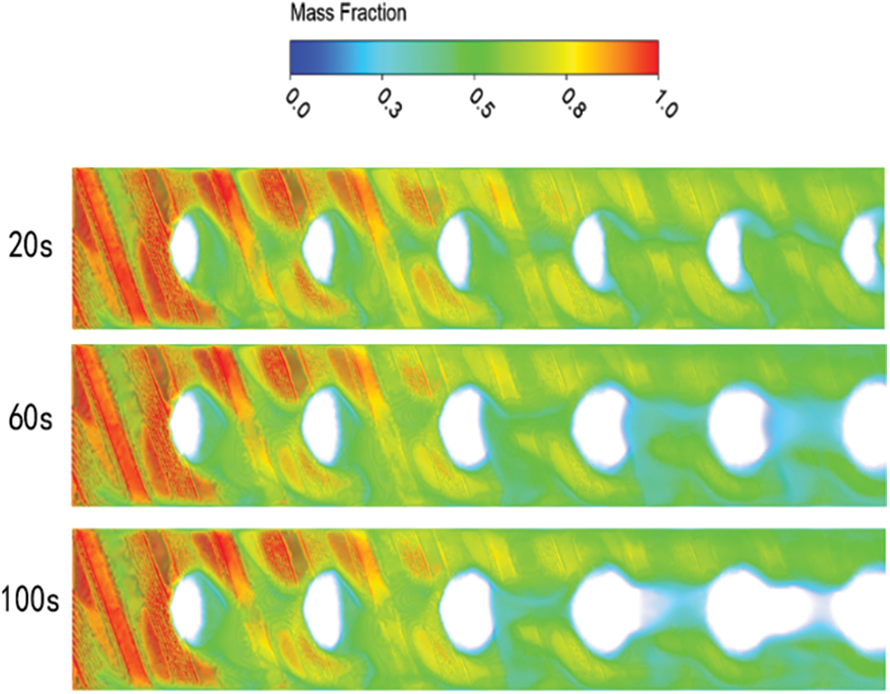
Figure 11: Liquid mass fraction of 045-type
4 Optimization of Anti-Solidification
The location of fluid icing inside the heat exchanger generally occurs first around the contacts and in the rear location, and the corrugation spacing determines the size of the contacts. Secondly, for the icing area, a smooth plate structure is better than a sharp plate structure, and the optimization study of heat exchanger anti-condensation is carried out according to the above two points.
The channel of a brazed plate heat exchanger is formed by superimposing two opposite corrugated plates, where the two plates intersect to form the contacts of the brazed plate heat exchanger. A schematic diagram of the contacts of the brazed plate heat exchanger is shown in Fig. 12. The previous section studied the corrugation spacing λ = 4.7 mm, and for a more obvious comparison, the corrugation spacing was increased and decreased, and two models of water channels with different spacings were designed with spacings of λ = 4.2 mm and λ = 5.2 mm, respectively. In this section, the solidification of the heat exchanger under different corrugation spacing is simulated and analyzed.
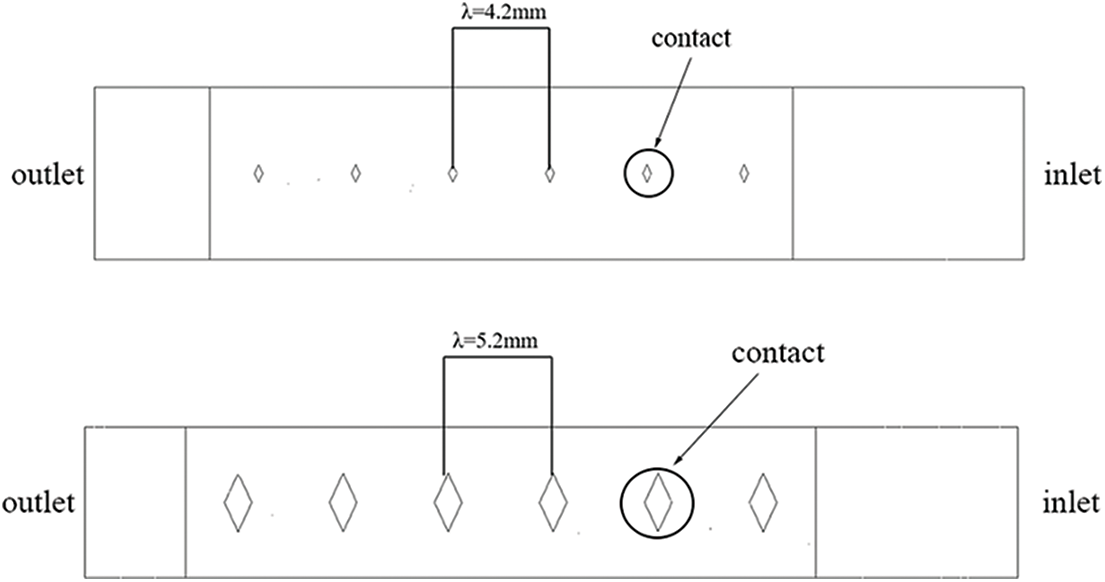
Figure 12: Two plates with different corrugation spacing
4.2 Effect of Corrugation Spacing on Solidification
Fig. 13 shows the distribution of liquid mass fraction in the computational domain for an inlet velocity of 0.1 m/s and corrugation spacing λ = 4.2 mm and λ = 5.2 mm. We can infer from the figure that the solidification area at 20 s is different due to the different contact sizes, and the solidification area for the corrugation spacing λ = 5.2 mm is more significant than that for the corrugation spacing λ = 4.2 mm. As time progresses, the contrast between the two is most evident in units 5 and 6. This is because the fluid boundary layer separation is evident at λ = 5.2 mm, leading to a decrease in the flow velocity behind the contacts and an increase in the occurrence of icing. As the corrugation spacing increases, the solidification area also increases. The three commonly used corrugation spacings are currently studied. Comparing the three shows that the corrugation spacing is optimal at 4.2 mm, followed by 4.7 mm, and the icing is most pronounced at 5.2 mm. Therefore, the subsequent optimization study will focus on the upper and lower range of the corrugation spacing of 4.2 mm.
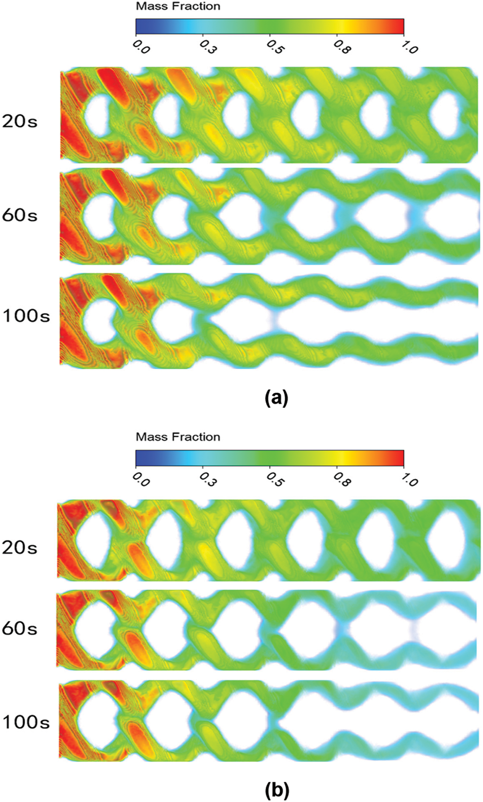
Figure 13: (a) Solidification at λ = 4.2 mm. (b) Solidification at λ = 5.2 mm
4.3 Structural Optimization Analysis of Heat Exchangers
According to the analysis in the previous subsection, the corrugation spacing has a large effect on the solidification area. In this section, six groups of water channel models with different corrugation spacing are established: λ = 4.0, 4.1, 4.2, 4.3, 4.4 and 4.5 mm, respectively. The influence of different corrugation spacing on flow, heat transfer and icing is further analyzed.
In this section, the distribution of the Nusselt number of heat exchangers with different corrugation spacing at different flow rates is calculated separately, as shown in Fig. 14. With the increase of inlet velocity, the heat transfer intensity of the heat exchanger rises. λ = 4.5 mm is the most intense heat transfer due to the increase in corrugation spacing and increasing contacts. This will affect the flow of fluid and has an obstructive effect on it, increasing reflux and resulting in an increase in convective heat transfer. The heat transfer effect is worst when λ = 4.0 mm and λ = 4.1 mm. The rise of corrugation spacing will lead to the expansion of the solidification area, and the best result is when the corrugation spacing is λ = 4.2∼4.3 mm.
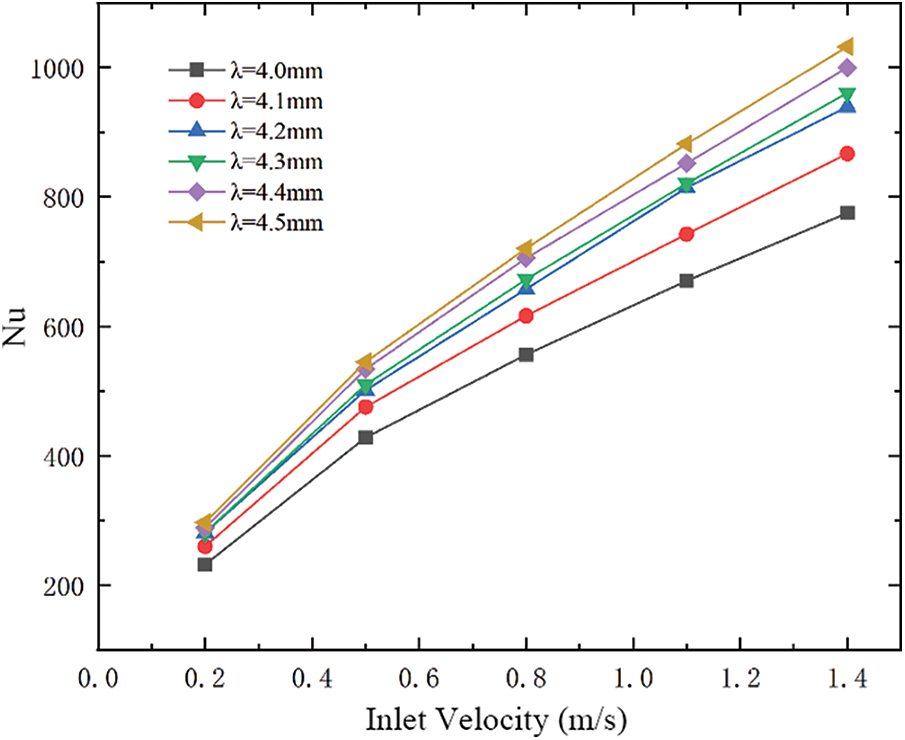
Figure 14: The influence of inlet velocity on Nusselt number of heat exchanger with different corrugation spacing
Fig. 15 shows the influence of inlet velocity of heat exchanger with different corrugation spacing on pressure drop. With the increase of inlet velocity, the pressure drop shows an increasing trend, with λ = 4.4 mm and λ = 4.5 mm having the most significant pressure drop. The pressure drop at the corrugation spacing λ = 4.0∼4.3 mm is closer. Therefore, through the calculation of six groups of cases and the comprehensive analysis of heat transfer and pressure drop, it is concluded that the influence on pressure drop and heat transfer is smaller when the corrugation spacing λ = 4.2∼4.3 mm, which can effectively prevent the internal fluid from solidifying in a large area.
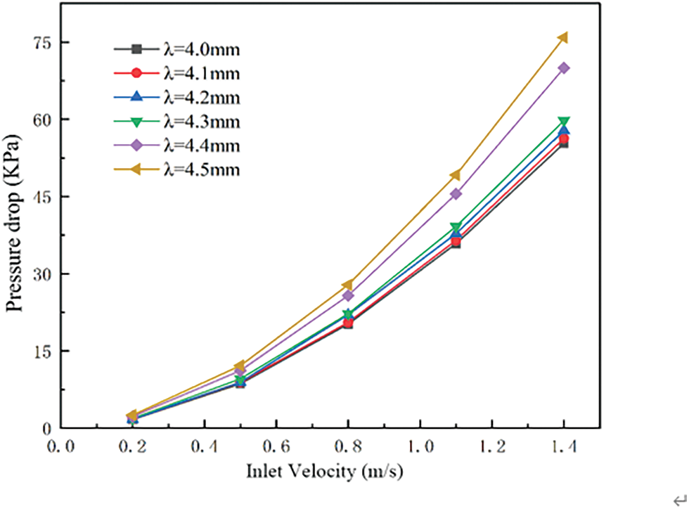
Figure 15: The influence of inlet velocity of heat exchanger with different corrugation spacing on pressure drop
Fig. 16 is the solidification of the fluid in the heat exchanger channel when the corrugation spacing λ = 4.0∼4.5 mm. From these diagrams, we can find that with the increase of the corrugation spacing, the icing area of the fluid also increases because the increase of the corrugation spacing leads to the increase of the contact area. The increase in the contact area will enhance its hindrance to the fluid. When the flow rate is low, the fluid behind the contacts will absorb the cold, but the cold cannot be quickly transferred out, resulting in a large area of icing. The optimal corrugation spacing is λ = 4.2 mm, considering the heat transfer, pressure drop and solidification.
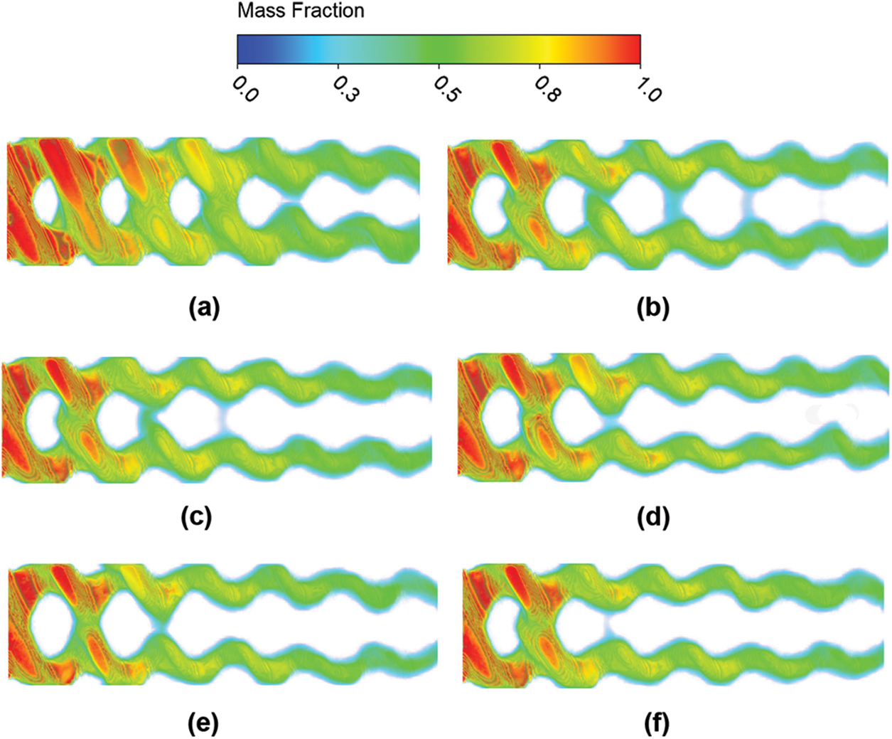
Figure 16: (a) Solidification at λ = 4.0 mm. (b) Solidification at λ = 4.1 mm. (c) Solidification at λ = 4.2 mm. (d) Solidification at λ = 4.3 mm. (e) Solidification at λ = 4.4 mm. (f) Solidification at λ = 4.5 mm
In this paper, the numerical simulation method is used to study the solidification phenomenon of the fluid inside the brazed plate heat exchanger, and the following conclusions are obtained by comparing the solidification phenomenon of the fluid inside the brazed plate heat exchanger with different corrugation spacing:
(1) The rear edge of the contacts of the brazed plate heat exchanger begins to solidify first. The lower the inlet flow rate is, the larger the solidification area at the contacts is. The position where the lower plate’s peak intersects the upper plate’s trough has a significant pressure change, a considerable flow resistance to the fluid, and a low flow rate.
(2) The solidification phenomenon of the water side of the 045-type brazed plate heat exchanger is severe. Although the solidification phenomenon of the 040-type brazed plate heat exchanger is not severe, the solidification area around the contacts is more significant than that of the 045-type.
(3) By comparing the six sets of data, it is found that the icing area of the fluid is smaller at the corrugation spacing λ = 4.2 mm, while the effect on heat transfer, pressure drop and solidification area is smaller.
Funding Statement: This research is supported by the Scientific Problem Tackling Program of Science and Technology Commission of Shanghai Municipality (18DZ1202000) and the Shanghai Local University Project “Research and Application of Key Technologies of New Efficient Micro Gas Turbine System” (No. 19020500900).
Conflicts of Interest: The authors declare that they have no conflicts of interest to report regarding the present study.
References
1. Madanan, U., Nayak, R., Chatterjee, D., Das, S. K. (2018). Experimental investigation on two-phase flow maldistribution in parallel minichannels with U-type configuration. The Canadian Journal of Chemical Engineering, 96(8), 1820–1828. https://doi.org/10.1002/cjce.23112 [Google Scholar] [CrossRef]
2. Thonon, B., Vidil, R., Marvillet, C. (2017). Plate heat exchangers: Research and developments. Journal of Enhanced Heat Transfer, 24 (1–6). https://doi.org/10.1615/JEnhHeatTransf.v24.i1-6.80 [Google Scholar] [CrossRef]
3. Kim, M. B., Park, C. Y. (2017). An experimental study on single phase convection heat transfer and pressure drop in two brazed plate heat exchangers with different chevron shapes and hydraulic diameters. Journal of Mechanical Science and Technology, 31(5), 2559–2571. https://doi.org/10.1007/s12206-017-0454-0 [Google Scholar] [CrossRef]
4. Li, W., Hrnjak, P. (2021). Visualization of two-phase refrigerant flow in the inlet header of brazed plate heat exchangers and its effect on distribution. International Journal of Refrigeration, 131, 483–492. https://doi.org/10.1016/j.ijrefrig.2021.07.007 [Google Scholar] [CrossRef]
5. Navarro-Peris, E., Alvarez-Pineiro, L., Schnabel, L., Corberan, J. M. (2021). Refrigerant maldistribution in brazed plate heat exchanger evaporators. Part B: Analysis of the influence of maldistribution on the evaporator performance. International Journal of Refrigeration, 131, 312–321. https://doi.org/10.1016/j.ijrefrig.2021.04.003 [Google Scholar] [CrossRef]
6. Luan, H. B., Tao, W. S., Zhu, G. Q., Chen, B., Wang, S. (2013). Development overview of fully welded plate heat exchanger. Chinese Science: Technical Science, 43(9), 1020–1033. [Google Scholar]
7. Gherasim, I., Taws, M., Galanis, N., Cong, T. N. (2013). Numerical and experimental investigation of buoyancy effects in a plate heat exchanger. Applied Thermal Engineering, 51(1–2), 347–363. https://doi.org/10.1016/j.applthermaleng.2012.09.009 [Google Scholar] [CrossRef]
8. Cai, Y., Jia, Z. G., Zhou, W. X., Shou, B. N. (2009). Study on numerical simulation of performance of herringbone corrugated plate heat exchanger. Computer and Applied Chemistry, 26(1), 105–108. [Google Scholar]
9. Abbas, A., Lee, H., Sengupta, A., Wang, C. C. (2020). Numerical investigation of thermal and hydraulic performance of shell and plate heat exchanger. Applied Thermal Engineering, 167. https://doi.org/10.1016/j.applthermaleng.2019.114705 [Google Scholar] [CrossRef]
10. Gullapalli, V. S., Sundén, B. (2014). CFD simulation of heat transfer and pressure drop in compact brazed plate heat exchangers. Heat Transfer Engineering, 35(4), 358–366. https://doi.org/10.1080/01457632.2013.828557 [Google Scholar] [CrossRef]
11. Zhang, A. L., Chen, Z. J., Wang, C. H. (2012). Study on anti-freezing performance of dry-type shell-and-tube heat exchanger for air source heat pump cold (hot) water unit. Refrigerating and Air Conditioning, 12(5), 28–31. [Google Scholar]
12. Zhang, L. A. (2006). Experimental study on anti-freezing performance of air-cooled heat pump water chiller. Refrigeration Air Conditioning and Electric Machinery, 6, 21–24. [Google Scholar]
13. Huang, H., Shu, P. C., Li, Z. H. (1999). Several issues in the design of air-cooled heat pump water chiller. Refrigeration, 2, 3–5. [Google Scholar]
14. Jin, Z. P. (1997). Research on anti-freezing system of air-cooled radiator. Journal of Electric Power, 4, 51–54. [Google Scholar]
15. Li, H. R., Duan, Y. Y., Zhang, Y. F., Chen, H. X. (2021). Numerical methods of ice-accretion software AERO-ICE. Acta Aeronautica et Astronautica Sinica, 42(S1), 726371. [Google Scholar]
16. Zhang, Y. B., Xu, H. Y. (2016). Numerical simulation and parameter optimization of heat transfer characteristics of plate heat exchanger. Vacuum and Cryogenic, 22(5), 296–300. [Google Scholar]
17. Hu, Z. H., He, X., Huang, T. K., Yang, M., Qin, G. H. (2016). Full-scale research on the fluid flow and heat transfer of low-flux chevron-type plate heat exchangers under the equal-velocity condition. Numerical Heat Transfer, Part A: Applications, 70(8), 887–901. https://doi.org/10.1080/10407782.2016.1214491 [Google Scholar] [CrossRef]
18. Della Torre, A., Montenegro, G., Onorati, A., Khadilkar, S., Icarelli, R. (2019). Multi-scale CFD modeling of plate heat exchangers including offset-strip fins and dimple-type turbulators for automotive applications. Energies, 12(15), 2965. https://doi.org/10.3390/en12152965 [Google Scholar] [CrossRef]
19. Kim, J. K., Oh, S. H. (2022). An estimation on the heat transfer performance of a full-scale shell-and-tube heat exchanger according to the change of mass flowrate. Journal of Power System Engineering, 26(4), 89–97. https://doi.org/10.9726/kspse.2022.26.4.089 [Google Scholar] [CrossRef]
20. Huang, Y. S., Jiang, W. T., Han, W. Z., Shi, W. S. (2015). Analysis of evaporative heat transfer and pressure drop characteristics of brazed plate heat exchanger. Refrigeration Technique, 35(6), 25–31. [Google Scholar]
21. Xu, Y., Meng, X. W., Han, X. (2021). Numerical simulation of icing condition in ice storage heat exchanger under steady state condition. Journal of Refrigeration Technology, 44(6), 51–58. [Google Scholar]
Cite This Article
 Copyright © 2023 The Author(s). Published by Tech Science Press.
This work is licensed under a Creative Commons Attribution 4.0 International License , which permits unrestricted use, distribution, and reproduction in any medium, provided the original work is properly cited.
 Downloads
 Citation Tools