
 Submit a Paper
 Propose a Special lssue
 Open Access
ARTICLE

Effect of the Arrangement of a New-Type of Turbulator Inserts on Heat Pipe Exchanger Performances
Department of Electromechanical Engineering, The University of Technology, Baghdad, Iraq
* Corresponding Author: Ibtisam A. Hasan. Email:
(This article belongs to the Special Issue: Recent advancements in thermal fluid flow applications)
Fluid Dynamics & Materials Processing 2023, 19(10), 2749-2759. https://doi.org/10.32604/fdmp.2023.027260
Received 21 October 2022; Accepted 14 December 2022; Issue published 25 June 2023
 View Full Text
 Download PDF
Abstract
This research tests the effect of introducing turbulators of a new type into a circular tube heat exchanger under a constant and uniform longitudinal heat flux condition. A 45 mm diameter copper tube with a length of 1,350 mm is utilized with a solid disk being inserted inside the tube, which consists of three sections, each one containing two slots. The slot is cut at a 45 degree angle toward the inner tube surface, which results in diverging the flow toward the inner hot tube surface in order to enhance the heat transfer process. Air is considered as the working fluid with Prandtl number 0.71. The Reynolds number spans the interval from 6,000–13,500, which indicates that the considered flow is turbulent. The heat exchanger performance is studied and analyzed in terms of average Nusselt number. The experimental results show that the Nusselt number value is directly proportional to the increase of the Reynolds number, and the number of turbulators inserts. With the use of three novel turbulators, the heat transfer was about 3.15 times higher than that in the smooth tube and the friction factor was about 1.11.Keywords
The main reason for introducing different types of turbulators or vortex generators in heat exchangers is to enhance their thermal performance. The challenge in designing a heat exchanger lies in the balancing of heat transfer and pressure drop along with cost and performance considerations. An effective heat exchanger should have a compact body that can achieve a high heat transfer rate at low pumping power [1]. Some previous studies have focused on ways of increasing the affected areas for heat exchange using fins or rough surfaces [2–4], which impact the boundary layer growth. Other ways to enhance the heat transfer process are via the use of inserts of elements of different geometries to increase local turbulence. Pressure drop is the main restricting factor for using these elements. Many researchers have conducted different studies on the impact of using different types of inserts to stimulate turbulence by introducing a vortex generator or obstacle to the path of the working fluid along the flow direction [1,5,6]. Jafari et al. [7] experimentally investigated heat transfer performance by utilizing swirl flow generators designed as a star cross-section distributed in the longitudinal direction. Other researchers [8–13] numerically studied the hydrodynamic characteristics of different types of heat exchangers using many types of turbulators. While some researchers used artificial neural networks to analyse heat exchanger performance [14–17].
This study offers a novel turbulence-maker (NT) insert, which is a solid disk that has been divided into three equal segments. Each segment has two slots around the disk center. The total area of the slots is equal to half the area of the disk. The six slots are cut at a 45-degree angle toward the ‘pipe’s inner surface, to deflect the flow of the working fluid toward the hot pipe surface thereby, providing more contact. The performance of the insert was compared with that of other insert-type devices commonly used in heat exchangers. The impact of the insert’s numbers on the convection rate as well as the pressure losses were studied. The working fluid utilized in this work was air. Finally, the precision of the outcomes of plain tube outcomes is confirmed via the available turbulent flow’s correlations.
The NT element is shown in Fig. 1. It is fabricated by dividing the disk surface into three equal segments. Each segment has two slots; one is close to the disk center while the other slot is placed close to the outer circumference of the disk. The total number of slots is six and the total area of the slots is half the total area of the disk surface.
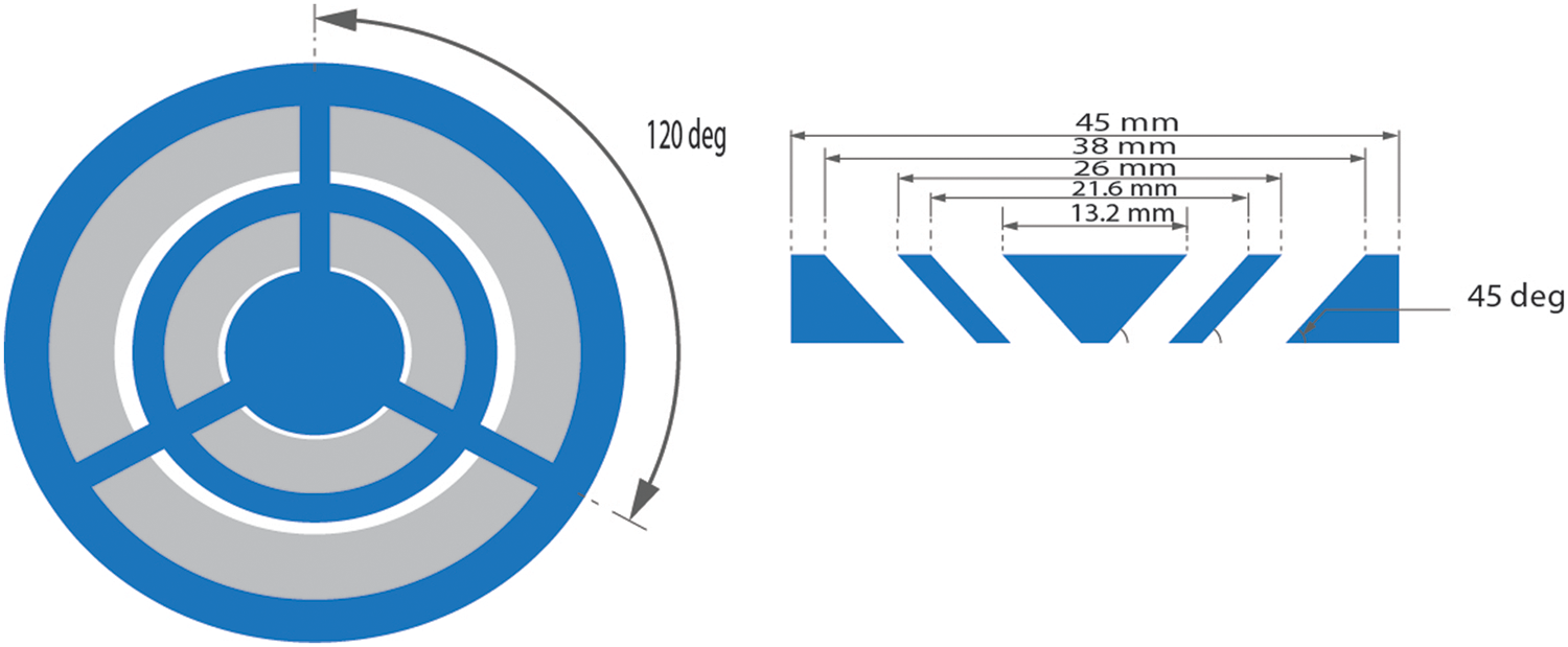
Figure 1: Schematic diagram of the NT
Each slot’s cutting line pierces the disk surface at a 45° inclination angle. When the working fluid enters the NT device, it is directed into the inner surface of the hot tube at 45°. This results in damage to the boundary layer growth. Fig. 2 shows the hypothetical physical flow of the working fluid.
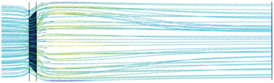
Figure 2: Physical flow behavior of the working fluid
NT device is designed as well as built by a 3-D printer machine. The raw material used to print the NT device is polylactic acid, which is considered to be one of the best materials available. The NT surfaces underwent treatments to obtain a smooth texture that reduces frictional losses.
The schematic diagram of the experimental setup is illustrated in Fig. 3. The test rig’s main parts are a calming section (inlet section), a test section which includes a heating element, and air supply system. For more details, see reference [6]. The test section is made from an aluminum tube with a length (L) of 1350 mm, an inner diameter (Di) of 45 mm, and an outer diameter (Do) of 50 mm. Uniform constant heat flux condition is applied, using an electrical heater. The outer test tube section is hermetically sealed to reduce heat loss at the outer tube surface. The average outer surface temperature of the test section wall was measured with eighteen calibrated thermocouples (Type-K) installed at different points along the axial direction of the tube.
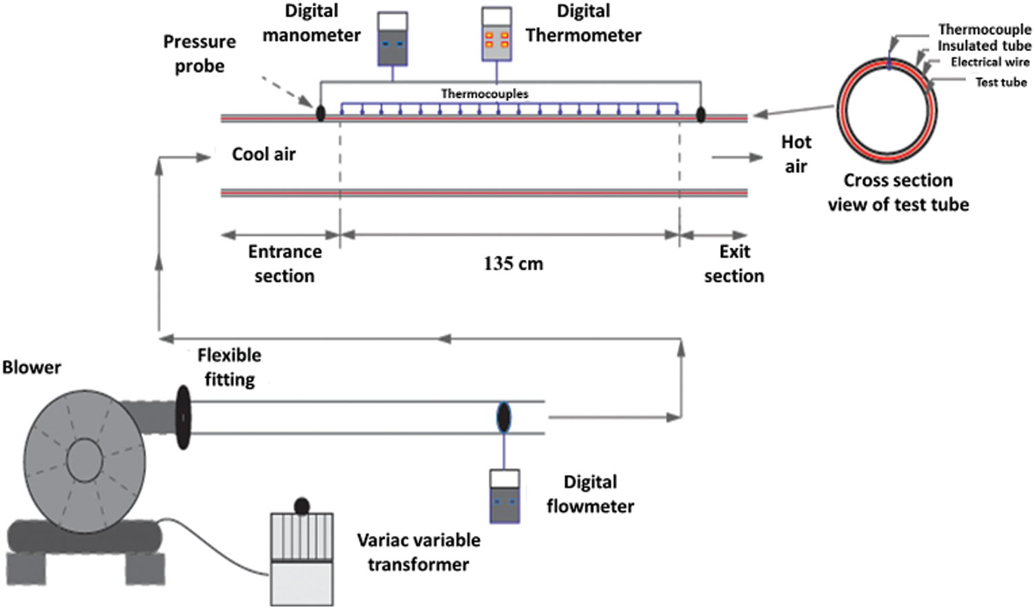
Figure 3: Schematic diagram of the experimental set-up
The inlet and outlet bulk temperatures of the working fluid are measured by installing two thermocouples. Three NT insert arrangements were tested. Fig. 4 illustrates the arrangements of the NT inserts. A plain tube and the three arrangements of NT inserts were tested as shown in Fig. 4.
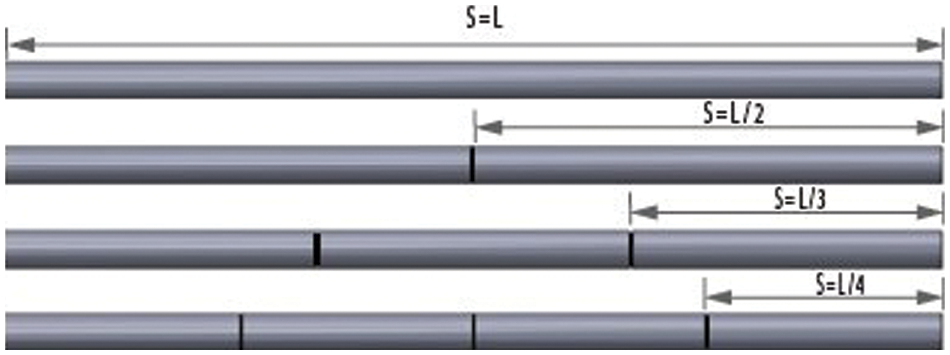
Figure 4: Arrangement of the NT inserts
The Reynolds numbers considered in this study are 6,000, 7,500, 9,000, 10,500, 12,000, and 13,500, which were experimentally investigated, to evaluate the impact of utilizing a turbulent flow maker on heat exchanger performance. The working fluid used is air, which flows through an insulated tube under conditions of uniform and constant applied heat flux. Total energy (Qs) supplied to the air is equal to the electrical energy provided to the system, as calculated from Eqs. (1) and (2).
where, V and I are the voltage and current, respectively.
The rate of transferred heat
where, Tbo and Tbi are the outlet and inlet fluid bulk temperatures, respectively.
The energy balance showed that the heat losses (radiation and convection) were not more than 0.8%–2.7%. The losses can be ignored if it is lower than 5% [18]. The considered amount of energy transferred is the average of
The energy balance for thermal energy transferred between the inner tube surface and the working fluid
where,
Average Nusselt number:
Reynolds number:
Friction factor:
where, U represents the mean flow velocity (m/s) and the pressure drop is represented by ΔP.
Fluid properties were considered at average bulk mean temperature, the thermal performance
The following relationship defined the Colburn j factor [6]:
There was a possible inaccuracy between the actual and the measured parameters for all experimental work in spite of the fact that confirmation, calibration, and other experimental laboratory steps for the proposed system were intended to enhance the reliability of the results. The uncertainty analysis is an important step in evaluating the difference between measured results and actual results. The Kline and McClintock method of analyzing the outcomes of independent variables and effects were utilized in this study [19]. The value of a variable (X1) is taken into account as a summary of the measured value (X2) and a specific uncertainty as:
The value of uncertainty for a parameter is a function of all the independent parameters
The uncertainty outcomes for the Nusselt number and friction factors were roughly 5.8% and 3.9%, respectively. While other parameters had a relative discrepancy of about 4%, it is an acceptable value that satisfies the required uncertainty and measurement device’s reliability.
Firstly, the plain tube was examined, and the measured results were evaluated against the calculated results of Dittus and Boelter for Nu, while friction factor correlation by Blasius [20].
Fig. 5 shows the results of the comparison between the Nusselt number measured and the correlation result. Fig. 6 presents the comparison between the friction factor measured and the correlation result. The agreement between measured and calculated values was observed closely. The deviation between the plain tube experimental results and correlations data for Nu and f were 4.1% and 4.42%, respectively. The minor and accepted discrepancy in experimental outcomes meant that the experiments could begin.
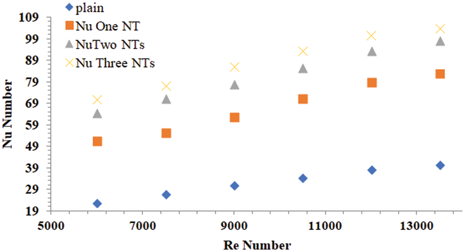
Figure 5: Comparison of Nusselt number for the plain tube
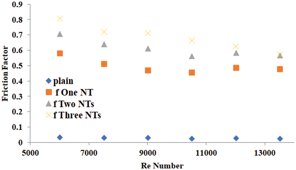
Figure 6: Comparison of friction factors for the different heat exchanger tubes
5.2 Axial Temperature Distribution
Fig. 7 shows the axial temperature distribution along the test section for a variety of NT numbers inserts, at 10,500 Reynolds number. The figure depicts the temperature changes along the test section. The surface temperature of the tube decreases when one or more NTs are inserted in the test section. Air turbulence intensity begins to grow when the NTs are inserted, and this influences the distribution of temperatures along the test section. The best temperature reduction was obtained when 3 (S = L/4) NT inserts were used. The enhancement in temperature distribution is directly proportional to the number of NTs. The NT inserts induce eddies in a turbulent flow. Two and three NT inserts had significant effects on heat exchanger performance. Fig. 8 shows the impacts of various Reynolds numbers on the temperature of the test section surface with two NT inserts (S = L/3). In this figure, the influences of two NT inserts can simply observe through following their line, at flow rate varies between 6,000–13,500.
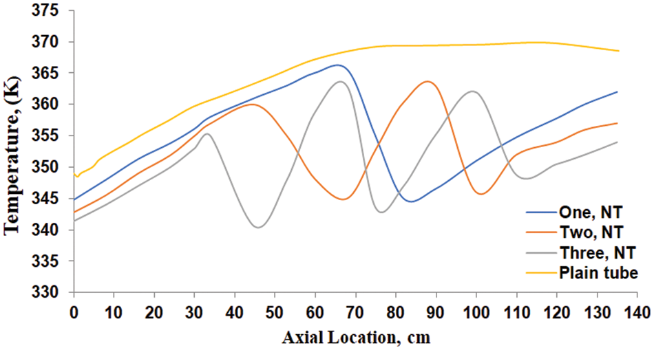
Figure 7: Surface temperature of test tube at Re = 10,500 and various NT no
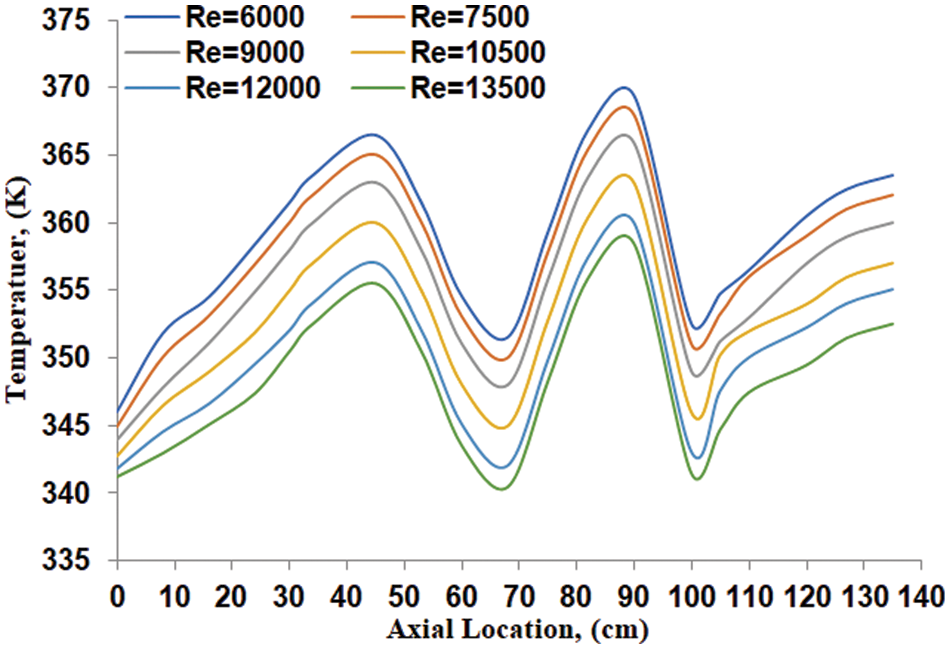
Figure 8: Surface temperature at different Re No. with two NT inserts
5.3 Heat Transfer Characteristic
The essential objective of the experimental work is to enhance heat transfer compared with smooth heat pipe exchangers. Figs. 9 and 10 present the results of all numbers of NT inserts on the transferred heat. Fig. 9 presents the experimental results of the Nusselt number vs. the Reynolds number for various numbers of NT inserts as well as for plain tube heat exchanger outcomes. The Nusselt No. increases along with the amplify in the Reynold number which leads to an augment in the heat transfer convective mode. Also, Fig. 9 illustrates the plain tube consistently had the lowest Nusselt number, and hence thermal performance while, with each increasing number of NT inserts the Nusselt number increased as the Reynolds number increased. This phenomenon was caused the eddy and vortex near the NT inserts that improved the mixing of fluid flow which results in an augmentation in the recurrence of eddy generation by the NT inserts, and an accompanying increase of heat transfer. It is thus apparent that the heat transfer rate is directly proportional to the number of NT inserts. The NT inserts are related to the induction of eddy flow, and increases of the pressure gradient in the radial direction. The highest enhancement in heat transfer is noted with three NT inserts, which is about 3.15 times greater than that of the smooth tube at the Re number of 6,000 Re No. as shown in Fig. 10. There were more increases in thermal performance with two and three NT inserts than with just one NT insert at the same Nusselt number.
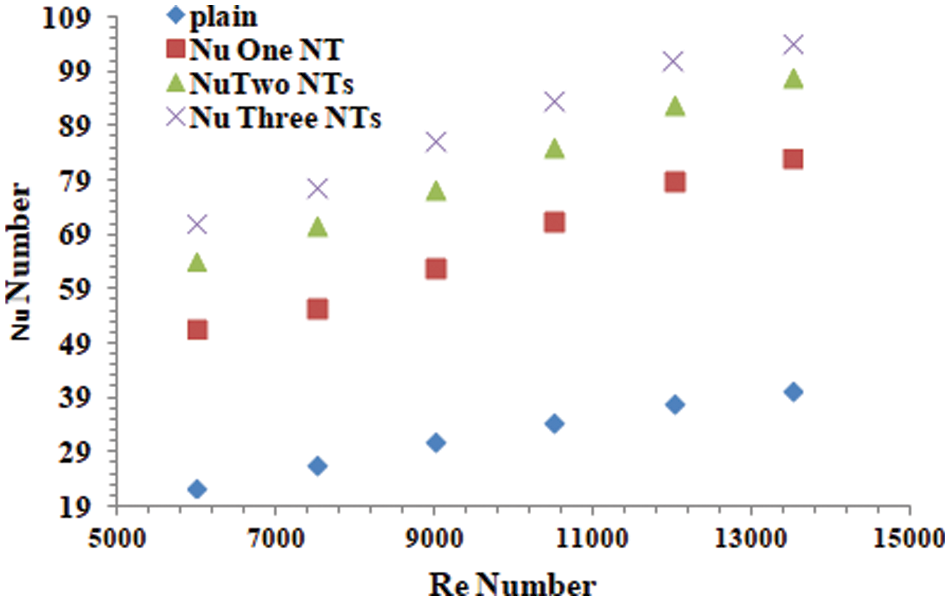
Figure 9: Nusselt number vs. Reynolds number for plain tube and tubes with different number of NT inserts
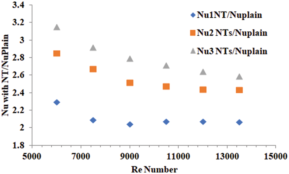
Figure 10: Heat transfer enhancement vs. Reynolds number
5.4 Fluid-Flow Characteristics
Fig. 11 sets out the experimental results of friction factor for tubes with different numbers of NT inserts vs. Reynolds number. For all cases, the friction factors generally decrease when the Reynolds number increases. It was apparent that the variation in friction factors values have a strong relation with the presence of NT inserts (tubes with inserts vs. plain/smooth tube). The friction factor in the tubes with inserts was consistently higher than in the smooth tube. The NT inserts contribute to inducing more losses nearby the boundary zones, causing a boosting of the eddy flow along the test tube. The highest friction was associated with the presence of three NT inserts while, one NT insert had the lowest value, for the cases of NT inserts, due to a minor disturbance in the flow. The friction factor outcomes had a similar tendency as that in reference [21].
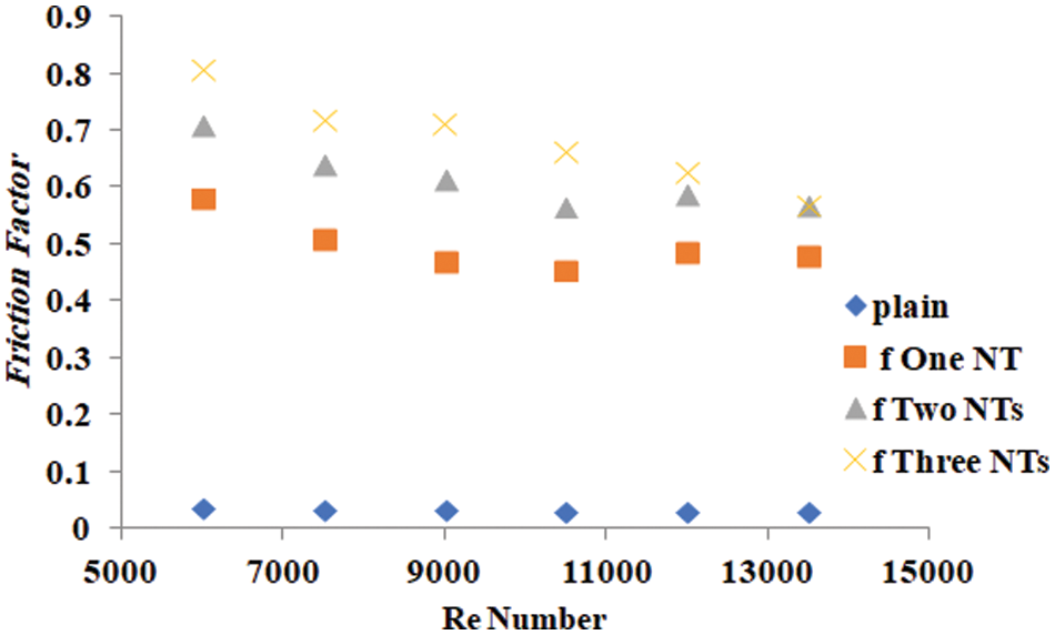
Figure 11: Friction factor vs. Reynolds number
The research results are utilized to analyze the j factors for various cases. Fig. 12 presents the relation between j-factors values vs. Reynolds number. It is apparent that the j factors are enhanced with increasing the number of NT inserts. An increase in longitudinal flow as an outcome of an increase in radial eddy flow improves efficiency. It is also obvious that these inserts have a significantly better performance improvement.
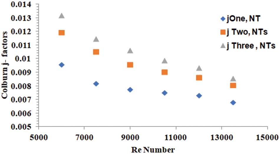
Figure 12: Colburn j-factors vs. Reynolds number for tubes with different number of NT inserts
The NT inserts create more turbulence, which is better for heat transfer than frictional losses. The performance factor is used as an efficient way to compare the practical value of using the NT inserts in the plain tube because of the augmentation of heat transfer associated with pressure losses. The results of an integrated evaluative factor take into consideration heat transfer efficiency and pressure losses. Fig. 13 shows the difference between the η values vs. Reynolds number. It is worth noting that at all the Re numbers, the performance increases with an increase in the number of NT inserts. Thus, inserts with different degrees of enhancement were revealed to not be detrimental to heat transfer compared to smooth tube performance. The trend of the NT distribution performance is similar over the range of Reynolds number, with the best thermal performance observed for the tube with three NT inserts, with a value of 1.11 at Reynolds number 6,000.
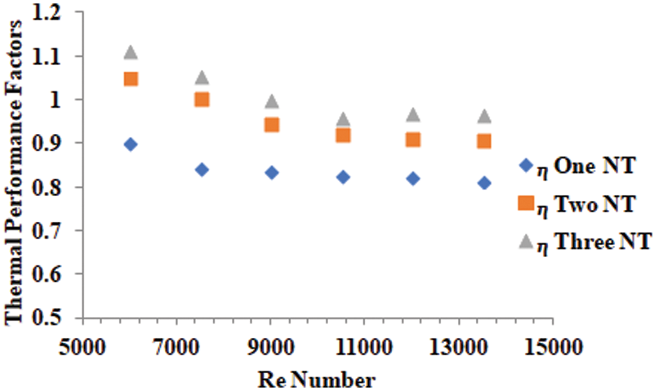
Figure 13: Thermal performance factor (η) vs. Reynolds number
6 Comparison with Previous Works
According to the experimental research, using NT inserts as a turbulence maker results in a significant increase in the factors of thermal efficiency and heat transfer. Data obtained from the literature is used in Fig. 14 to compare the current study with some similar prior work. There are various advantages of using NT inserts compared to other insert types. It is relatively straightforward to fabricate the current NT inserts since they are made by using a 3D-printer. The cost of fabrication is significantly cheap, as only one process is utilized in NT insert fabrication, compared to the cost of the fabrication of twisted tapes or conical rings as inserts. Additional difficulties arise from the need to maintain uniform twist ratios in twisted tape as well as the potential for material and time wastage. In contrast to other geometries used in this kind of previous studies, the usage of NT inserts can be advantageous.
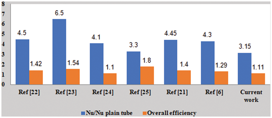
Figure 14: Comparison of the current study’s results with previous studies [22–25]
In this experimental investigation, the parameters of the flow in a heat pipe exchanger with NT inserts to control the turbulent flow are determined, including the friction factor, thermal efficiency factor, and Nusselt number. The effect of the NT has also been investigated with different numbers of insertions. The Nusselt number and friction factor values for the NT inserts are greater compared to those of smooth tubes across the whole set of geometric and flow parameters. When three NT are inserted, the greatest enhancement in heat transfer is seen. The characteristic performance of the heat exchanger is nearly regular in all cases because the increase in heat transfer from the NT insert is more beneficial than the effect of the increase in friction losses. The performance parameters output of three NT is 18.8% greater than one NT at Re equal to 6,000.
The efficiency of the current work is better than that reported in previous work, as shown in Fig. 14. In addition, the NT used in the current work is simpler to fabricate than the inserts used in previous work.
This research has great potential application for the development of tubes for heat exchange that can increase thermal performance yet remain compact. In practical terms this work is important in different industrial fields such as oil and gas, and food processing. For future work, this mechanism of heat transfer enhancement could be associated with using nanofluid as the working fluid.
Funding Statement: The authors received no specific funding for this study.
Conflicts of Interest: The authors declare that they have no conflicts of interest to report regarding the present study.
References
1. Thote, S. A., Singh, N. P. (2023). Analysis of friction and heat transfer characteristics of tubes with trapezoidal cut twisted tape inserts. Fluid Dynamics & Materials Processing, 19(3), 711–722. https://doi.org/10.32604/fdmp.2022.021651 [Google Scholar] [CrossRef]
2. Sadeghzadeh, H., Aliehyaei, M., Rosen, M. A. (2015). Optimization of a finned shell and tube heat exchanger using a multi-objective optimization genetic algorithm. Sustainability, 7, 11679–11695. [Google Scholar]
3. Attalla, M., Maghrabie, H. M. (2020). An experimental study on heat transfer and fluid flow of rough plate heat exchanger using Al2O3/water nanofluid. Experimental Heat Transfer, 33(3), 261–281. [Google Scholar]
4. Hasan, I. A., Fafraj, S. R., Mohmma, I. A. (2020). An elaborate review for micro-fin heat sink. Engineering and Technology Journal, 38(1), 105–112. [Google Scholar]
5. Salih, I. A. (2017). Thermal characterization of turbulent flow in a tube with discrete coiled wire insert. Journal of Engineering and Development, 18(1), 1–12. [Google Scholar]
6. Hasan, I., Wafa, M., Enaya, Y. (2021). Thermo-hydraulic performance evaluation of heat exchanger tube with vortex generator inserts. Thermal Science, 26(2B), 1545–1555. https://doi.org/10.2298/TSCI210528289H [Google Scholar] [CrossRef]
7. Jafari, M., Farajollahi, A., Gazori, H. (2020). The experimental investigation concerning the heat transfer enhancement via a four-point star swirl generator in the presence of water–ethylene glycol mixtures. Journal of Thermal Analysis and Calorimetry, 144, 167–178. [Google Scholar]
8. Menni, Y., Chamkha, A. J., Ameur, H. (2020). Enhancement of the hydrodynamic characteristics in shell-and-tube heat exchangers by using W-baffle vortex generators. Periodica Polytechnica Mechanical Engineering, 64(3), 212–223. [Google Scholar]
9. Du, J., Wu, X., Li, R., Cheng, R. (2019). Numerical simulation and optimization of a mid-temperature heat pipe exchanger. Fluid Dynamics & Materials Processing, 15(1), 77–87. https://doi.org/10.32604/fdmp.2019.05949 [Google Scholar] [CrossRef]
10. Ameur, H. (2020). Effect of corrugated baffles on the flow and thermal fields in a channel heat exchanger. Journal of Applied and Computational Mechanics, 6(2), 209–218. [Google Scholar]
11. Jalili, P., Ganji, D. D., Nourazar, S. S. (2018). Investigation of convective-conductive heat transfer in geothermal system. Results in Physics, 10, 568–587. [Google Scholar]
12. Jalili, P., Kazerani, K., Jalili, B., Ganji, D. D. (2022). Investigation of thermal analysis and pressure drop in non-continuous helical baffle with different helix angles and hybrid nano-particles. Case Studies in Thermal Engineering, 36, 102209. [Google Scholar]
13. Jalili, B., Aghaee, N., Jalili, P., Ganji, D. D. (2022). Novel usage of the curved rectangular fin on the heat transfer of a double-pipe heat exchanger with a nanofluid. Case Studies in Thermal Engineering, 35, 102086. [Google Scholar]
14. Batur, A., Açıkgöz, Ç., Mercan, H., Dalkılıç, A. S., Wongwises, S. (2022). Prediction of heat transfer coefficient, pressure drop and overall cost of double-pipe heat exchangers using the artificial neural network. Case Studies in Thermal Engineering, 39, 1–30. https://doi.org/10.1016/j.csite.2022.102391 [Google Scholar] [CrossRef]
15. Acikgoz, O., Çolak, A. B., Camci, M., Karakoyun, Y., Dalkilic, A. S. (2022). Machine learning approach to predict the heat transfer coefficients pertaining to a radiant cooling system coupled with mixed and forced convection. International Journal of Thermal Sciences, 178, 107624. [Google Scholar]
16. Mercan, H., Sonmez, F., Çolak, A. B. (2022). Determination of heat transfer rates of heavy-duty radiators for trucks having flattened and double-U grooved pipes with louvered fins by ANN method: An experimental study. The European Physical Journal Plus, 137. [Google Scholar]
17. Shafiq, A., Çolak, A. B., Sindhu, T. N. (2022). Modeling of soret and dufour’s convective heat transfer in nanofluid flow through a moving needle with artificial neural network. Arabian Journal for Science and Engineering, 48, 2807–2820. [Google Scholar]
18. Hasan, I., Kareem, I., Attar, D. (2019). Improved photovoltaic panel performance using a cylindrical pin fins as a heat sink. University of Thi-Qar Journal for Engineering Sciences, 10, 84–97. https://doi.org/10.31663/tqujes.10.2.336(2019) [Google Scholar] [CrossRef]
19. Moffat, R. J. (1988). Describing the uncertainties in experimental results. Experimental Thermal and Fluid Science, 1(1), 3–17. [Google Scholar]
20. Shah, R. K., Sekulić, D. P. (2003). Fundamentals of heat exchanger design. USA: John Wiley & Sons, Inc. [Google Scholar]
21. Kuma, A. (2018). Experimental investigation on thermal performance and fluid-flow characteristics in heat exchanger tube with solid hollow circular disk inserts. Applied Thermal Engineering, 100, 227–236. [Google Scholar]
22. Eiamsa-ard, S., Kongkaitpaiboon, V., Nanan, K. (2013). Thermohydraulics of turbulent flow through heat exchanger tubes fitted with circular-rings and twisted tape. Chinese Journal of Chemical Engineering, 21(6), 585–593. [Google Scholar]
23. Promvonge, P. (2008). Thermal augmentation in circular tube with twisted tape and wire coil turbulator. Energy Conversion and Management, 49(11), 2949–2955. [Google Scholar]
24. Promvonge, P., Eiamsa-Ard, S. (2007). Heat transfer in a circular tube fitted with free-spacing snail entry and conical-nozzle turbulator. International Communications in Heat and Mass Transfer, 34(7), 838–848. [Google Scholar]
25. Promvonge, P. (2008). Heat transfer behaviors in round tube with conical ring insert. Energy Conversion and Management, 49(1), 8–15. [Google Scholar]
Cite This Article
 Copyright © 2023 The Author(s). Published by Tech Science Press.
This work is licensed under a Creative Commons Attribution 4.0 International License , which permits unrestricted use, distribution, and reproduction in any medium, provided the original work is properly cited.
 Downloads
 Citation Tools