| Fluid Dynamics & Materials Processing |
DOI: 10.32604/fdmp.2023.019790
ARTICLE
A Numerical Study on Supersonic Combustion Optimization Based on the Streamwise Vortex-Couple Method
China Aerodynamics Research and Development Center, Mianyang, 621000, China
*Corresponding Author: Yongkang Zheng. Email: zhengyk@cardc.cn
Received: 15 October 2021; Accepted: 01 June 2022
Abstract: In this paper, some typical methods to promote mixing in supersonic combustion are reviewed, and the fluid-dynamic mechanism underpinning the development of the supersonic shear layer in the presence of a streamwise vortex is analyzed through computational fluid dynamics. It is proven that the streamwise vortex-couple method is an excellent approach to enhance mixing. A specific combustor design is proposed accordingly.
Keywords: Supersonic combustion; streamwise vortex; numerical simulation
The scramjet differs from a typical ramjet in that it performs combustion in a supersonic flow rather than reducing the flow to subsonic levels. Although the concept of supersonic combustion has long been proposed, its engineering application has yet to be fully implemented. The difficulty results not only from the heat problem but also from the following two aspects: (1) the fuel mixing problem and (2) the combustion organization problem, including the Mach number, temperature, pressure, heating quantity, and pressure loss,
All numerical cases were simulated in a finite difference framework using an in-house code developed by the authors. The three-dimensional chemical non-equilibrium NS equations in Cartesian coordinates are as follows [3]:
where:
In the above, u, v, w are x, y, z components of velocity, respectively. p,
The source term
where
where
The static enthalpy and the specific heat at constant pressure are considered with temperature and species-dependent thermodynamic properties as follows:
where
Thermal conductivity and molecular viscosity are calculated using the Sutherlands formula for each species. The Wilkes formula [5] is then applied to calculate the mixture’s thermal conductivity and molecular viscosity. Moreover, mass diffusivity is calculated according to the kinetic theory as follows [6]:
where
The total energy per unit mass of mixture E and the total enthalpy per unit mass of mixture H are defined as follows:
The high-order scheme has the advantage of less numerical dissipation in describing the flow field with high resolution and has less dependence on the grid for the same numerical accuracy. Meanwhile, both the accuracy and robustness of the scheme are required in engineering problems, making the third-order scheme a good compromise. Numerical verifications are conducted for a class of third-order schemes for engineering applications on different problem types [7]. In this study, the third-order procedures are applied to the numerical simulation of supersonic combustion to capture the flow-field structure and investigate the scheme’s rationality.
The scheme is introduced in the form of one-dimensional hyperbolic equations as follows:
Consider the conservative difference scheme and write it in a semi-discrete form:
The positive flux portion with the third (or higher)-order scheme in the linear condition can be written as follows:
where:
where
To capture the discontinuous structure (such as the shock wave), however, the nonlinear mechanisms are needed to increase scheme dissipation in the weighted form:
where:
A continuous variational rescale technology is proposed [7] by changing the index p. For low-speed problems:
As shown in previous investigations, the turbulence model is crucial in predicting the flow-field variables and the interaction between turbulence and combustion for supersonic combustion simulations. Menter’s shear stress transport (SST) model [9] has extensive applications in engineering and was used in this study due to its good performance with lower computational cost and more numerical robustness [9]. The SST turbulence model introduces the original model inside the boundary layer region and switches into the standard model outside the boundary layer region and in free shear flows [9]. The transport equations used for the SST turbulence model take the following form:
The governing equations of the turbulence model are as follows:
Details of the equations can be found in reference [9]. The decoupling method [10] is applied, implying that NS and turbulence equations are solved.
The finite difference method is used in this study, and the compressible NS equations are discretized on a single structured grid. Based on its robustness and high resolution of stationary discontinuity, the nonoscillatory nonfree-parameters dissipative difference scheme (NND) [11] is adopted for the inviscid flux vectors. The viscous flux vectors were calculated using a second-order central difference scheme. The implicit LUSGS method is employed for time marching. In order to meet the computational requirements and improve computational efficiency, a massage-passing interface is introduced for a massive parallel computation. Because of the single-block body-fitted grid, the load balancing problem can be solved simply by splitting the grid equally.
Numerical simulations of the straight and expanded tubes are implemented in this study. From the straight tube problem, the distribution range of each species in the flow field and several vital parameters are analyzed, and the principle of using detonation waves to organize the combustion is illustrated. A more detailed study on the proposal of using a streamwise vortex couple to enhance supersonic combustion is achieved via the expanded tube problem. A third-order scheme is applied, and the turbulence model is considered. Some results which differ from previous studies are also obtained.
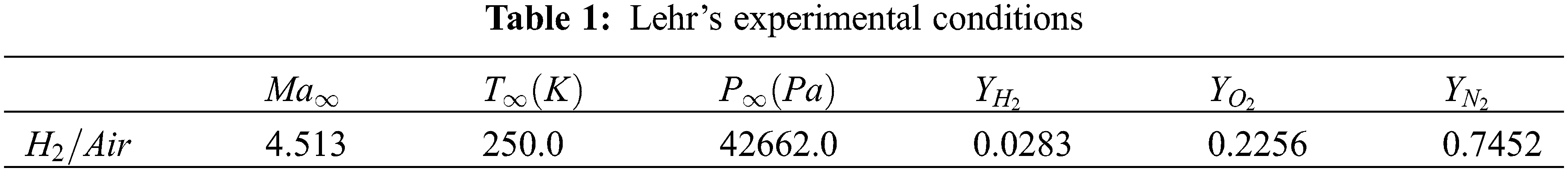
Lehr’s experiment [12] provided experimental schlieren diagrams of a supersonic combustor, flow-field temperature distributions, and experimental temperature measurement results. This is the most commonly used example for testing numerical calculation methods and combustion models in supersonic combustion simulations. Shock-induced combustion phenomena, ranging from decoupled shock-deflagration systems to overdrive oblique detonation waves, were experimentally investigated by Lehr’s experiment [12]. The flux splitting scheme, NND, is tested under the experimental conditions listed in Table 1 to estimate its accuracy and robustness on shock capture for supersonic combustion simulations.
First, the grid sensitivity analysis is studied to eliminate the influence of grid errors. Three grid spacing scales are then adopted to represent the grid’s independence: coarse, medium, and fine grids. The detailed grid information and the distribution of the medium grid are shown in Table 2 and Δ is the first grid-scale in the wall-normal direction.
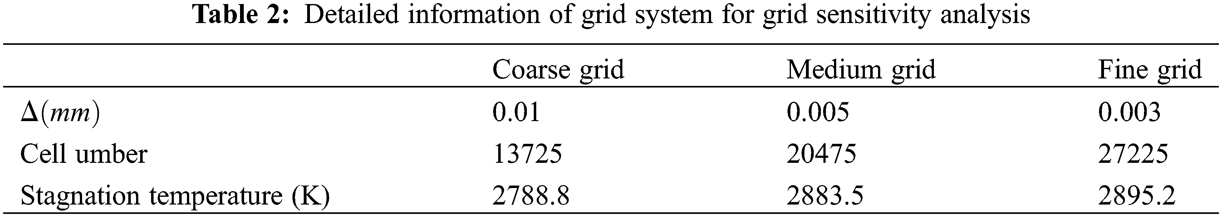
Fig. 1 shows the temperature contours of the decoupled shock-deflagration overlaid on the shock location [13] obtained from the numerical results of the medium grid. Fig. 2 shows the distribution of the temperature along the X direction on the stagnation line. Combustion does not begin immediately behind the shock wave, as depicted. Instead, the combustion front appears to be separated from the shock wave by an induction zone. This behavior can also be observed clearly from the stagnation line temperature in Fig. 2. The numerical results for the three sets of grids are nearly identical in the upstream region. As the flow and combustion process develops after the detonation wave, the medium and fine grids remain constant, whereas the coarse grid begins to diverge with time.
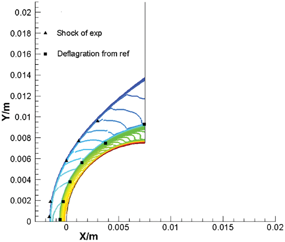
Figure 1: Decoupled shock-deflagration system, temperature contours
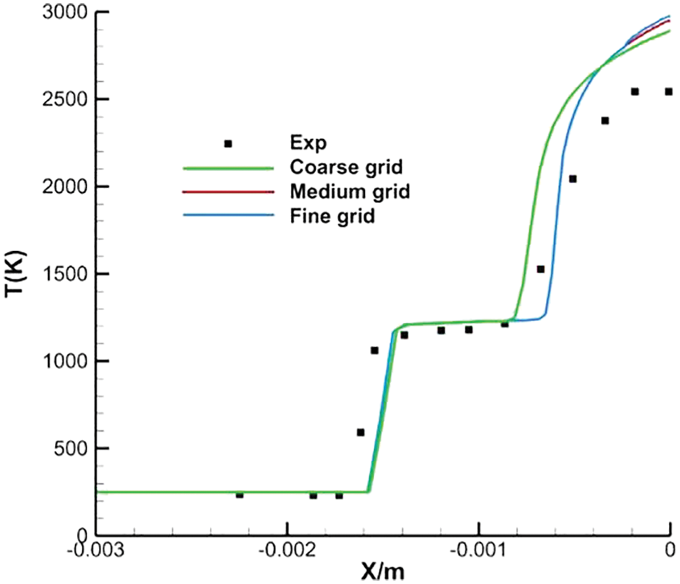
Figure 2: Stagnation line temperature for decoupled shock-deflagration system
The numerical method predicts an accurate ignition position as the temperature distribution is consistent with the experiment data. Thus, the numerical implementation can then be applied to supersonic combustion simulations.
The structure problem between fully mixed hydrogen and oxygen is discussed in the following part, and the combustion is proposed at
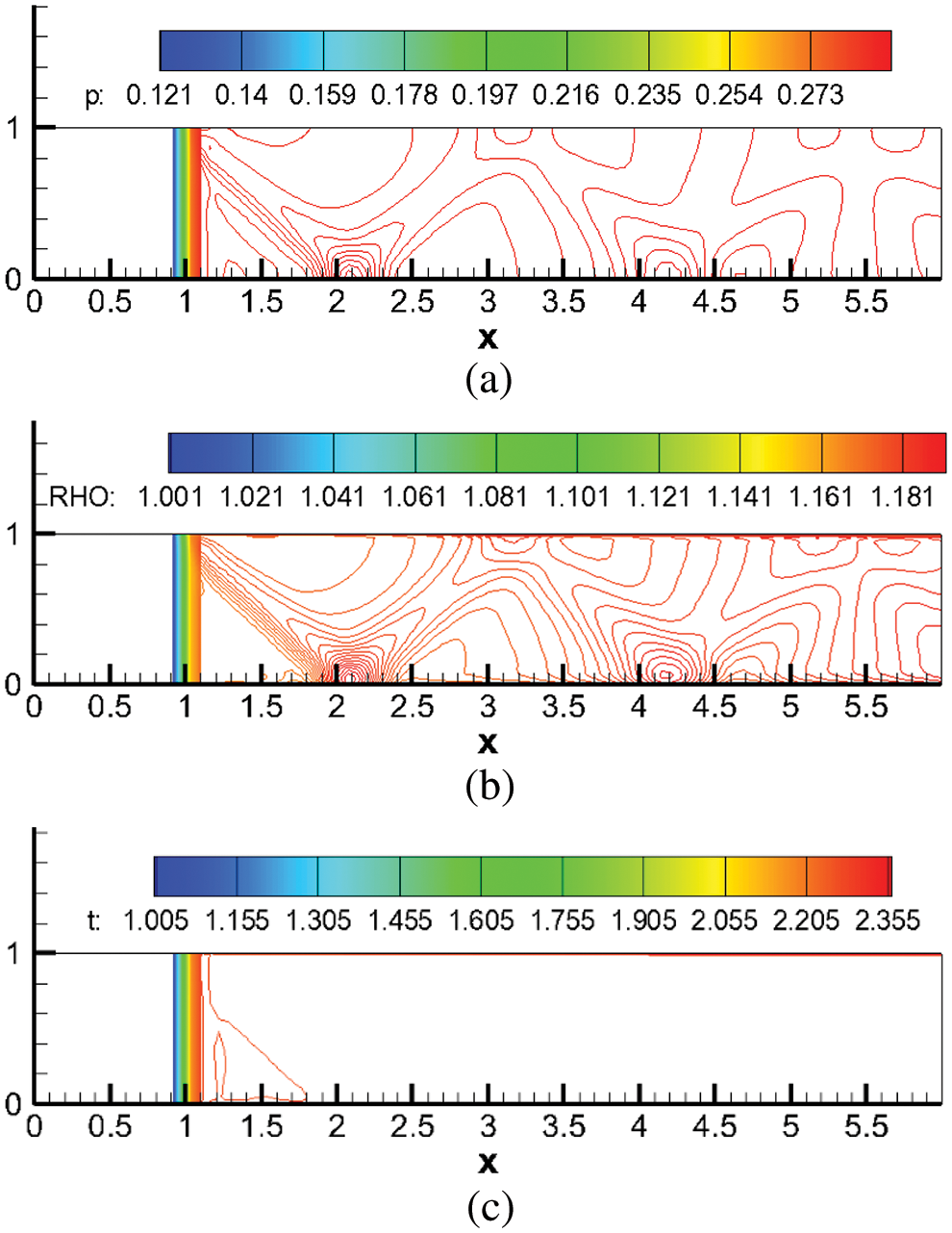
Figure 3: Numerical results of channel combustion in fully mixing condition, (a) pressure, (b) density, (c) temperature
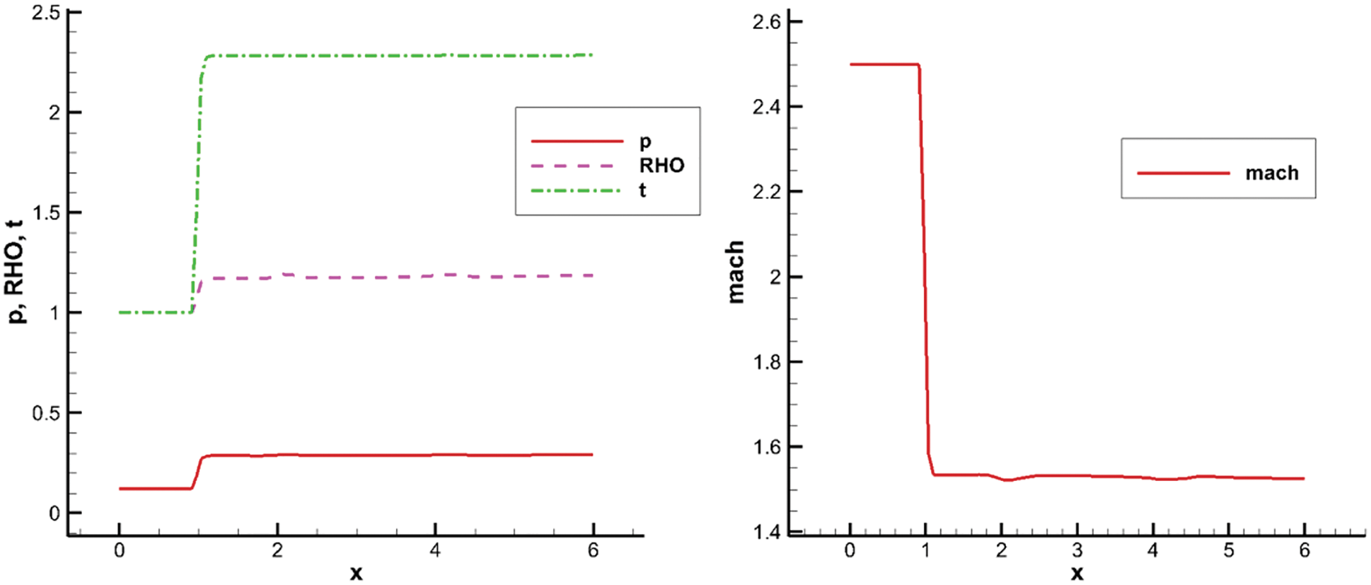
Figure 4: Numerical results of channel combustion along the axis, left: pressure, density, temperature, right: Mach number
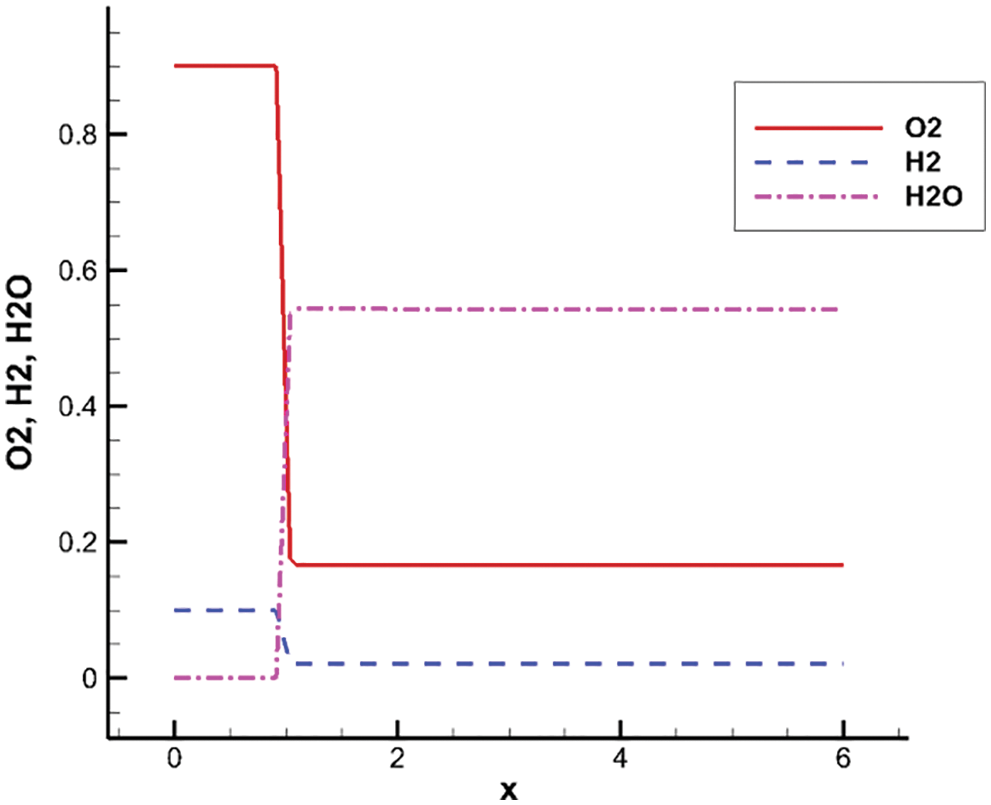
Figure 5: Numerical results of channel combustion along the axis, mass fraction of main species
Two important parameters related to the combustor temperature and pressure are given in [1],
where
3.3 Streamwise Vortex-Couple Proposal for Expand Tube Problem
It has been demonstrated that the streamwise vortex can enhance fuel mixing and improve the supersonic combustion efficiency from both flow mechanism and numerical simulations in [1,12,14,15]. Thus, a more detailed numerical simulation is conducted to investigate the effect and influence of streamwise vortex couples on supersonic combustion in this study.
Fig. 6a shows the sketch maps of the combustor and fuel injector. The length, width, and entrance height of the combustor are 170, 31, and 12.2 cm, respectively. The expansion angle on the top wall is 1°. The injection device consists of an expansion surface and two wedges on the expansion surface. Fig. 6b shows that the wedge has a thickness of 5 cm and a compression surface of 5° in the first 11 cm of the wedge, while the remaining 11-cm in length expands to the underside of the wall. The two wedges are arranged in the middle, with a 7-cm gap between them. Two injection holes are ranged on the lower surface of the wedge, from which hydrogen is ejected at an angle of 12° along the flow direction. The computational mesh is arranged 11 cm to the region upstream of the wedges to resolve the turbulent boundary layer.
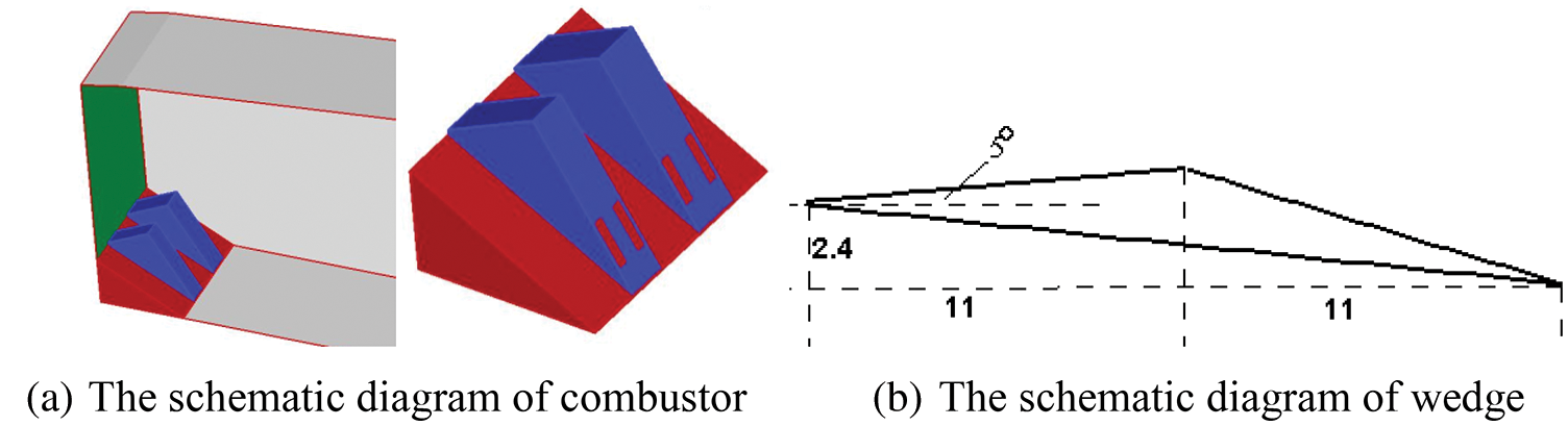
Figure 6: Sketch maps for combustor
A single-block body-fitted grid is used for the calculation, and compression is performed along the wall directions to meet the requirements of the viscous boundary layer for NS equations. The grid is taken as
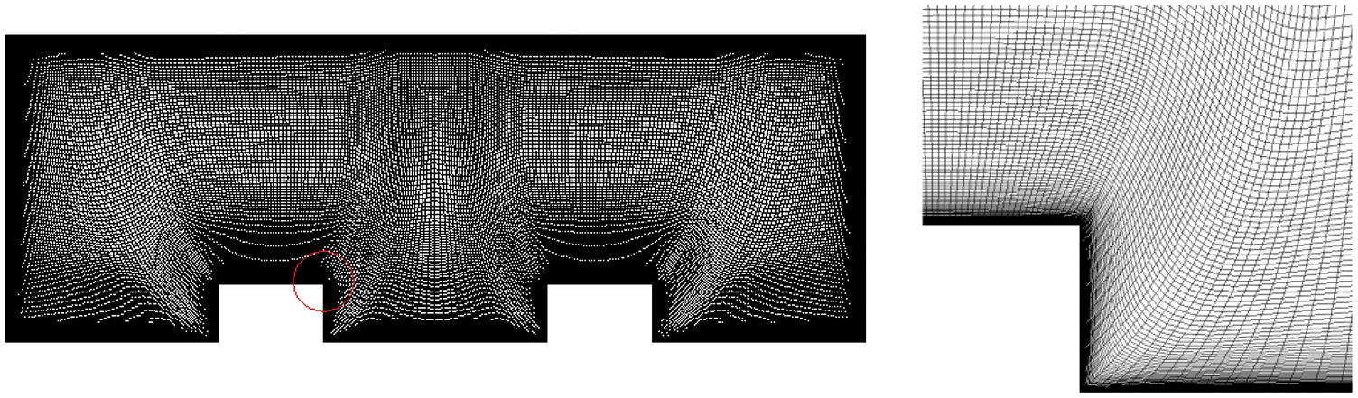
Figure 7: Grid distribution in the cross-section
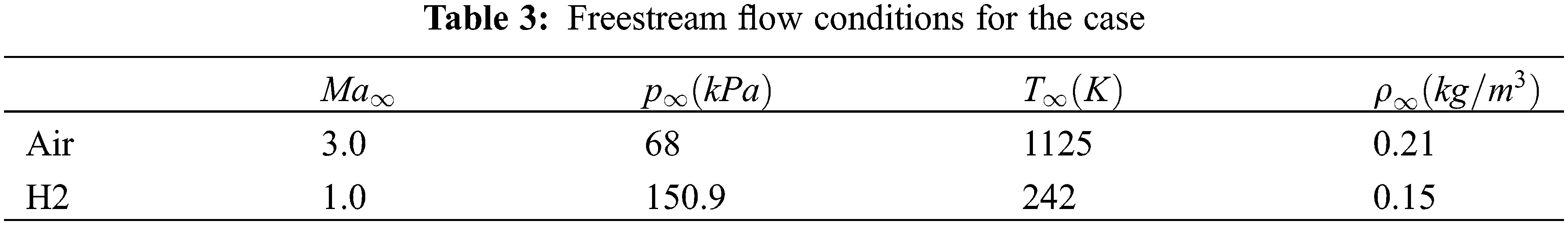
Parallel computing using the aforementioned third-order scheme and the SST turbulence model is implemented with 30 CPUs under the following conditions (Table 3):
3.3.1 Organization of Combustion
First, the feasibility of the project for enhancing the supersonic combustion efficiency is quantitatively analyzed based on the five aspects of combustion organization mentioned in Section 1.1.
(1) Mach number: The Mach number is taken as 3.0 for the combustor inlet and 1.0 for the injection hole.
(2) The problem of
The pressure distribution of a spanwise section through one of the injection holes is shown in Fig. 8.
(3) The Mach number of the outlet is
(4) The problem of
satisfying the aforementioned requirement:

Figure 8: Pressure contours of a spanwise section through one of the injection holes
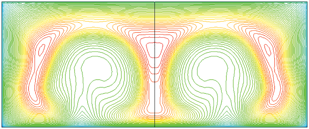
Figure 9: Mach number contours of outlet
Other results related to organizational problems are given in Figs. 10–12:
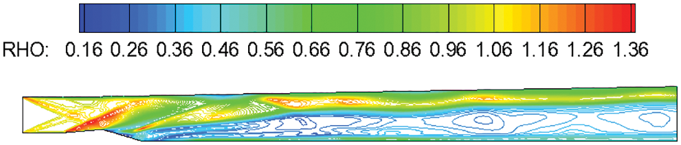
Figure 10: Density contours of a spanwise section through one of the injection holes
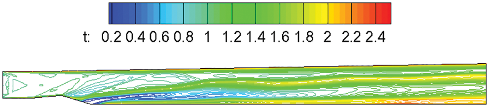
Figure 11: Temperature contours of a spanwise section through one of the injection holes
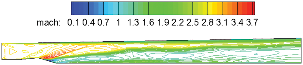
Figure 12: Mach number contours of a spanwise section through one of the injection holes
The discontinuity in the flow field is caused by weak detonation waves and the supersonic combustion, of which occurs all over the field. From the aforementioned analysis, the design parameters of the project satisfy the requirements of the five aspects of supersonic combustion organization, and supersonic combustion can be theoretically achieved.
The phenomenon of streamwise vortex couple acting on the flow field to enhance mixing and improve combustion efficiency is further analyzed. According to the theory of streamwise vortex couple enhancing mixing [1], the project aims to enhance fuel gas and air mixing using the transport mechanism of a supersonic vortex, to improve combustion efficiency. Numerical calculation result shows that the outlet combustion efficiency with the water component is presented in Fig. 13 as follows:
where the inlet and outlet mass flow rates of water and the inlet mass flow rate of hydrogen are respectively given as
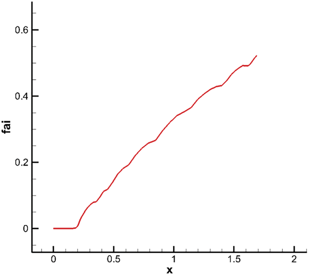
Figure 13: Combustion efficiency profiles along flow direction
The combustion efficiency curve shows that the combustion efficiency increases with an increase in x, but does not reach a relatively constant value, implying that the reaction is unsaturated. More research is needed on how to continuously increase the mixture to improve combustion efficiency within a limited range of combustor length.
Numerical results on fuel mixing are given in Figs. 14–16:
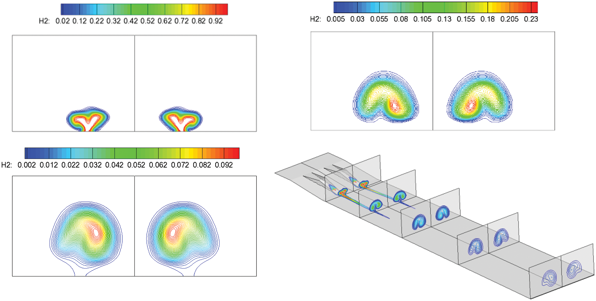
Figure 14: H2 contours along the flow direction, followed by: Spout, center section and outlet
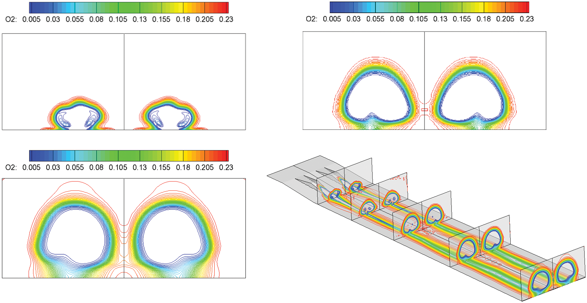
Figure 15: O2 contours along the flow direction, followed by: Spout, center section and outlet
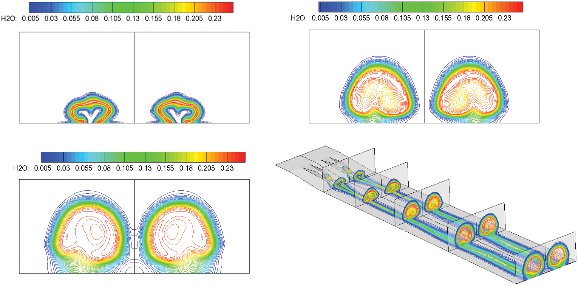
Figure 16: H2O contours along the flow direction, followed by: Spout, center section and outlet
By introducing a streamwise vortex couple, the vortex circumrotates from inside to outside under a pressure gradient, forming the mass transport. Thus, the incoming air and jet hydrogen are fully mixed and burned. Oxygen is almost entirely burned out in most of the middle area at the exit of the combustor. Concurrently, the hydrogen is exhausted, implying that the streamwise vortex couple significantly enhances supersonic combustion.
Under the condition in which the grid is compressed near the wall, and considering the influence of the boundary layer, the combustion mostly occurs in the combustor’s internal region, which is different from the results in previous calculations. The air vortex occurs near the bottom area, and a ribbon shape is formed by exhausting the oxygen with water generation, indicating that combustion occurs in the boundary layer. Concurrently, there are obvious differences between the results of laminar and turbulent flows. Under turbulent conditions, the combustion is more efficient considering the effect of turbulence in the boundary layer. For simplicity, only the turbulent numerical results are presented in this study.
The Mach number contours and streamlines at different locations are given in Figs. 17 and 18:
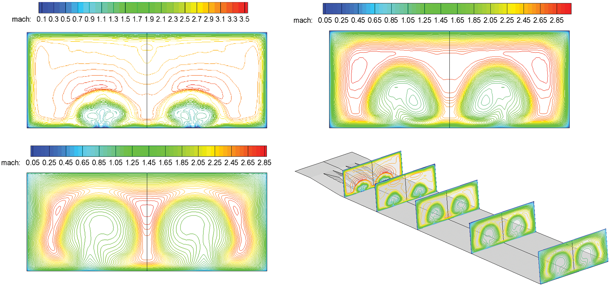
Figure 17: Mach number contours along the flow direction, followed by: Spout, center section and outlet
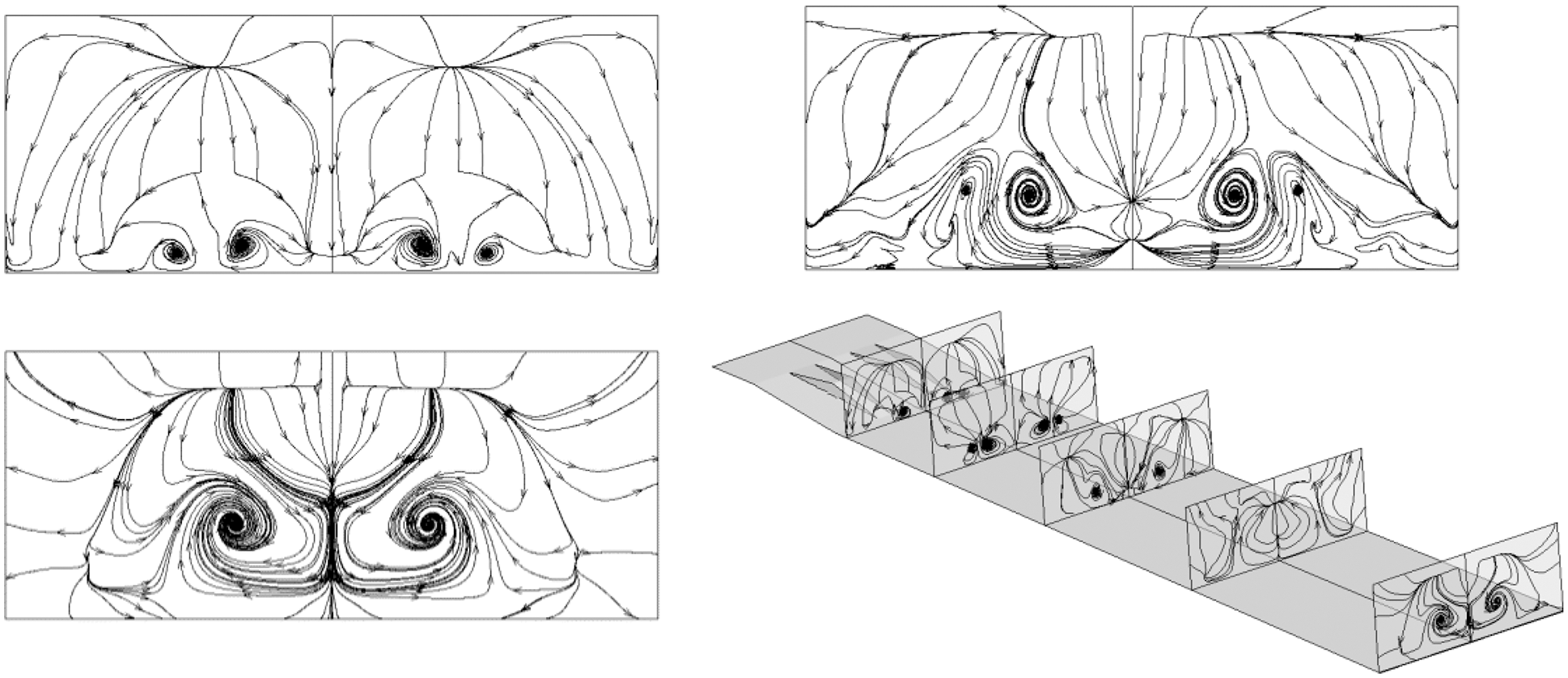
Figure 18: Streamlines along the flow direction, followed by: Spout, center section and outlet
The distributions of species and streamlines in different sections of the flow field correspond to each other. Taking the H2O distribution as an example, the distribution of H2O is obviously in the shape of a vortex at different sections. Vortexes coalesce near the injection holes in the front half of the combustor. The transport phenomenon is formed by rolling up the substance to the vortex center in the vortex movement. Two small vortical regions with low content, corresponding to H2O distribution, exist inside a sizable vortical region with high content, implying that the hydrogen and oxygen are constantly rolled up into the vortex center with combustion. The vortex in the combustor’s rear half is not as strong as that in the front half. Because the reactions have been sufficiently conducted, the vortex in the H2O contours has become slightly more prominent, whereas small vortical regions with low water content gradually disappear along the flow direction, indicating that combustion is complete and hydrogen and oxygen are exhausted. In conclusion, the distribution of species contours and flow structures are related. The vortex enhances combustion by mass transport and changes the content of each species, whereas the temperature and density of flow vary because of the reactions. Thus, component distribution and flow structure are related and influence each other.
It gives the speed of sound distribution at the center cross-section in Fig. 19:
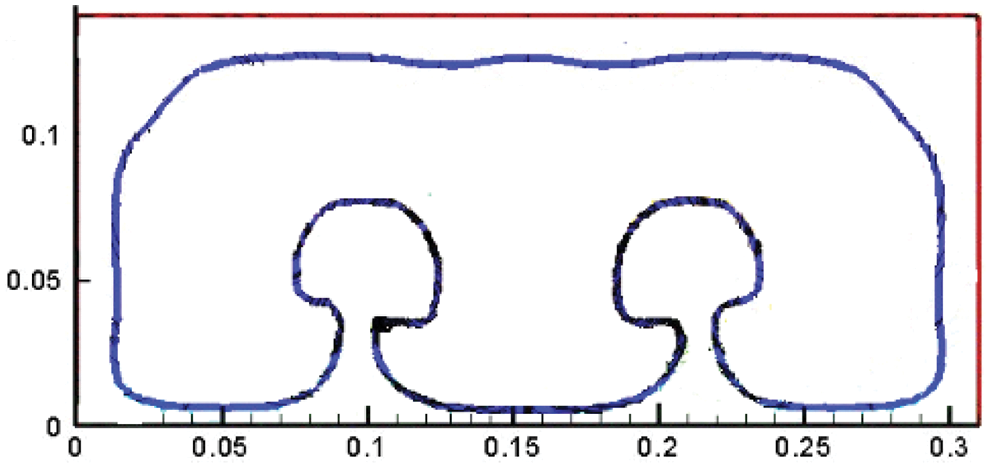
Figure 19: Speed of sound line at the center cross-section [1]
Fig. 20 shows the numerical results obtained in this study using the fine grid and turbulence model, which is different from those obtained in a previous study. Supersonic combustion occurs almost all over the combustor. Concurrently, the subsonic region is mainly concentrated in the boundary layer region near the wall, which illustrates the theoretical feasibility of this proposal to achieve supersonic combustion.
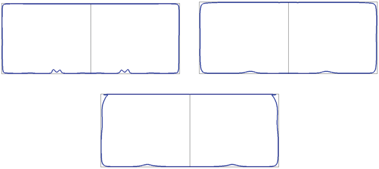
Figure 20: Speed of sound line along the flow direction, followed by: Spout, center section, and outlet
A numerical simulation of the process of supersonic combustion is performed with a fine grid using a third-order scheme and an SST turbulence model. The numerical results illustrate the following points:
First, the discontinuity in the flow field is a weak detonation wave in terms of combustion organization, which is consistent with the original purpose of organizing combustion using the detonation wave principle. In terms of fuel mixing, the introduction of a streamwise vortex couple enhances the mixing of hydrogen and oxygen and improves combustion efficiency.
Second, because of the numerical scheme, grid, and turbulence model, the flow field details are partly different from the prevenient laminar numerical results based on a second-order scheme. The numerical results show that supersonic combustion occurs almost all over the combustor. Concurrently, the subsonic region is mainly concentrated in the boundary layer region near the wall, which theoretically supports the proposal’s design.
Third, based on the aforementioned two points, the numerical simulation results show that achieving supersonic combustion in a hypersonic ramjet is theoretically feasible.
Acknowledgement: The first author, Yongkang Zheng acknowledges the National Laboratory for Computational Fluid Dynamics for the computational resources and technical support.
Funding Statement: This work was supported by the National Natural Science Foundation of China (No. 12002193), and the Shandong Provincial Natural Science Foundation, China (No. ZR2019QA018).
Conflicts of Interest: The authors declare that they have no conflicts of interest to report regarding the present study.
References
1. Zhang, H. X. (2012). The exploration for supersonic combustion in the scramjet engine. Physics of Gases-Theory and Applications, 7(4), 1–14. [Google Scholar]
2. Du, Z. B. (2019). RANS study of steady and pulsed gaseous jets into a supersonic crossflow. International Journal of Heat and Mass Transfer, 136, 157–169. DOI 10.1016/j.ijheatmasstransfer.2019.02.103. [Google Scholar] [CrossRef]
3. Zheng, Y. K. (2020). Numerical investigations on the impact of Turbulent Prandtl number and Schmidt number on supersonic combustion. Fluid Dynamics & Materials Processing, 16, 637–650. DOI 10.32604/fdmp.2020.09694. [Google Scholar] [CrossRef]
4. Evans, J. S. (1980). Influence of chemical kinetics and unmixedness on burning in supersonic hydrogen flames. AIAA Journal, 18(2), 188–193. [Google Scholar]
5. Wilke, C. R. (1950). A viscosity equation for gas mixtures. Chemical Physics, 18(4), 517–591. [Google Scholar]
6. Gao, Z. X. (2016). On the laminar finite rate model and flamelet model for supersonic turbulent combustion flows. International Journal of Hydrogen Energy, 41, 13238–13253. DOI 10.1016/j.ijhydene.2016.06.013. [Google Scholar] [CrossRef]
7. Li, Q. (2013). On a class of center-typed third order difference scheme orienting to engineering utilizations. Acta Aerodynamica Sinica, 31(4), 466–472. [Google Scholar]
8. Zhu, J. (2017). Numerical study on the convergence to steady state solutions of a new class of high order WENO schemes. Journal of Computational Physics, 349, 80–96. DOI 10.1016/j.jcp.2017.08.012. [Google Scholar] [CrossRef]
9. Menter, F. R. (1994). Two-equation eddy-viscosity turbulence models for engineering applications. AIAA Journal, 32(8), 1598–1605. DOI 10.2514/3.12149. [Google Scholar] [CrossRef]
10. Brown, J. L. (2002). Turbulence model validation for hypersonic flows. AIAA Paper 2002–3308, 1–22. [Google Scholar]
11. Zhang, H. X. (1991). NND schemes and their applications to numerical simulation of Two- and three-dimensional flows. Advances in Applied Mechanics, 29, 193–256. DOI 10.1016/S0065-2156(08)70165-0. [Google Scholar] [CrossRef]
12. Lehr, H. F. (1972). Experiments on shock-induced combustion. Journal of Aeronautica Acta, 17, 589–597. [Google Scholar]
13. Soertrisno, M. (1991). Simulation of the flow field of a ram accelerator. AIAA Paper 1991–1915, 1–14. DOI 10.2514/6.1991-1915. [Google Scholar] [CrossRef]
14. Arail, T. (2014). Effect of incoming boundary layer on supersonic mixing layer generated by wall-mounted ramp injector. AIAA Paper 2014–3216, 1–7. DOI 10.2514/6.2014-3216. [Google Scholar] [CrossRef]
15. Arail, T. (2015). Interaction between supersonic cavity flow and streamwise vortices for mixing enhancement. AIAA Paper 2015–3613, 1–12. DOI 10.2514/6.2015-3613. [Google Scholar] [CrossRef]
16. Wang, J. Y. (2020). Numerical study of high-temperature nonequilibrium flow around reentry vehicle coupled with thermal radiation. Fluid Dynamics & Materials Processing, 16(3), 601–613. DOI 10.32604/fdmp.2020.0962. [Google Scholar] [CrossRef]
 | This work is licensed under a Creative Commons Attribution 4.0 International License, which permits unrestricted use, distribution, and reproduction in any medium, provided the original work is properly cited. |