| Fluid Dynamics & Materials Processing |
DOI: 10.32604/fdmp.2022.018789
ARTICLE
Reinforcement of Clay Soils through Fracture Grouting
1School of Civil Engineering, Beijing Jiaotong University, Beijing, 100044, China
2Central Research Institute of Building and Construction Co., Ltd., MCC Group, Beijing, 100088, China
3Beijing Geotechnical Anchorage Engineering Center, China Jingye Engineering Co., Ltd., Beijing, 100088, China
*Corresponding Author: Shaozhen Cheng. Email: 14115325@bjtu.edu.cn
Received: 17 August 2021; Accepted: 16 December 2021
Abstract: Fracture grouting is widely used for building foundation reinforcement, however the underpinning mechanisms are still not clear. Using numerical results about a single-hole fracture grouting process as a basis, a model composed of soil and grouting veins has been created to analyze the reinforcement mechanism. The influence weights of the grouting vein skeleton and compaction effect have been studied, thereby obtaining relevant information on the compressive modulus of the considered composite soil. The research results show that the compaction effect plays a leading role in the soil fracture grouting reinforcement. The grouting pressure, the hardened grouting vein modulus, and the shape of the grouting veins all influence the compressive modulus of the composite soil.
Keywords: Building foundation; fracture grouting; composite soil; reinforcement mechanism; reinforcement effect
Fracture grouting is widely used to strengthen the construction foundation to prevent and control its settlement. For example, before the subway goes under a building, it is usually necessary to reinforce the soil under the building to reduce settlement. Although fracture grouting is widely used in engineering, its reinforcement mechanism is still not very clear yet. After fracture grouting is finished, a grouting composite soil body is formed. The grouting veins and the soil are tightly combined in the composite soil body. The modulus of grouting veins in the composite soil is relatively high, which plays a role in skeleton support. The grout also compacts the surrounding soil during the grouting process. However, it is not clear which plays the leading role.
The mechanism of grouting reinforcement has always been the focus of engineers and technicians. Bai et al. [1] studied the splitting grouting process and reinforcement mechanism of soft soil through indoor simulation tests. They believed that the grout consolidation body played a supporting role similar to fishbone. Nichols et al. [2] performed a small-scale model compaction grouting tests in a geotechnical centrifuge to examine the development of a compaction grout bulb and the response in the surrounding soil. Zhou et al. [3] introduced the expansion and reinforcement principle of fracture grouting in the soft flow plastic silt layer. They believed that the grouting veins in the soil have a compacting effect and are beneficial to the reconsolidation of the soil. Fransson et al. [4] postulated a new parameter to assess hydromechanical effects in single-hole hydraulic testing and grouting. Li et al. [5] developed a three-dimensional fracture grouting test system to study the diffusion and reinforcement mechanism of sequential fracture grouting. The research suggests that fracture grouting mainly has the reinforcement effect of compaction and skeleton support, but who plays the leading role has not been studied in depth. Chang et al. [6], Toru et al. [7], and others studied the improvement effect of compensation grouting on the mechanical properties of rock and soil through field tests. Still, they did not analyze the principle of reinforcement in depth. Wang et al. [8] studied the variation law of single axial compressive strength and permeability coefficient of stone body strengthened by penetration grouting. Lan et al. [9] explored the grouting reinforcement mechanism of heterogeneous rock and soil in a fault fracture zone. Hsiao et al. [10] conducted cyclic triaxial and resonant column tests to understand the beneficial effects of various grouted sands on liquefaction resistance and dynamic properties. Niu et al. [11] designed a 3D grouting test system to explore the slurry diffusion law and reinforcement mechanism of split grouting in a filling soil.
Although scholars have carried out some experimental studies, it is difficult for laboratory experiments to fully simulate the state of the soil layer. Pure theoretical research and experiment are difficult to visually reflect the dynamic expansion process and the shape of the grouting veins. The numerical simulation can not only simulate the state of the formation, but also reflect the dynamic expansion process. Eriksson et al. [12] discussed a method for prediction of grout spread. The grout propagation was based on the Bingham model for flow. Moës et al. [13] applied the extended finite element method to modeling growth of arbitrary cohesive cracks. Pantuso et al. [14] presented a FEM/VOF hybrid formulation to model underfill Encapsulation. Lecampion [15] used the extended finite element method to solve the hydraulic fracture problems. An internal pressure inside the crack was taken into account. Carrier et al. [16] considered the problem of a fluid-driven fracture propagating in a permeable medium. The fracture propagation is governed by a cohesive zone model and the flow within the fracture by the lubrication equation. Sarris et al. [17] investigated the main parameters that influence the propagation of a fluid-driven fracture in a poroelastoplastic continuum. Koyama et al. [18] developed a three-dimensional numerical model based on an equivalent continuum approach to simulate grout injection. Guo et al. [19] used a finite element software to implement two and three-dimensional numerical models for grouting of intersected fractures in hydrostatic conditions. Suri et al. [20] presented the development of a three-dimensional Computational Fluid Dynamics (CFD) modelling technique for the prediction of proppant-fluid multiphase flow in hydraulic fractures. Although scholars have carried out some research on hydraulic fracturing and fracturing grouting. Most of them are aimed at the expansion of the crack tip. Few studies have obtained the entire grouting propagation process and the complete grouting vein morphology .Chen et al. [21,22] used a FEM/VOF numerical method to model the fracture grouting in soil. The expansion process and shape of the grouting veins were obtained in the simulation.
Although some studies on the effect of fracture grouting reinforcement were carried out, most of them focused on a single fracture in fractured rock or soil. However, one grouting hole usually produces multiple grouting veins when in clay soil. The grouting effect evaluation rarely focuses on the composite soil formed by the combination of grouting veins and soil. It is impossible to take samples containing multiple grouting veins on-site for confined compression tests. Therefore, the numerical method becomes an effective method. In this paper, we used an FEM/VOF numerical method [21,22] to obtain the shapes of the grouting veins. Then, a composite soil model consisting of grouting veins skeleton and soil is established. By calculating the compressive modulus of the composite soil, the synergistic reinforcement mechanism of the skeletal effect and the compaction effect was analyzed. In addition, the influence of the grouting pressure, the strength of the grouting stone body, and the initial modulus of the soil on the compressive modulus of the grouting composite were analyzed.
2 Fracture Grouting Composite Soil Model and Grouting Effect Display
2.1 Conceptual Model of Fracture Grouting Composite Soil in Clay Soil
After the fracture grouting in soil finished, the grouting vein and the soil formed a tightly combined grouting composite soil with two solid media, see Fig. 1 below. The distribution of grouting veins has a certain degree of randomness, and the grouting veins expand in all directions.

Figure 1: Composite soil conceptual model of single-hole fracture grouting
During fracture grouting, the infiltration and diffusion of the grout have a compacting effect on the surrounding soil. After the grouting is condensed, it forms a rigid grouting vein to play a skeletal support effect in the composite soil. Compaction and skeleton support are the two main mechanisms of fracture grouting reinforcement. The reinforcement effect is related to the grouting pressure, the shape of the grouting vein, and the mechanical properties of the soil itself. The compressive modulus of grouting composite soil is a quantitative index to evaluate the reinforcement effect. It is mainly affected by compaction and skeleton effects.
2.2 Numerical Simulation of Fracture Grouting and Verification
The numerical simulation method based on finite element (FEM) and fluid volume function (VOF) hybrid formulation method [21,22] was adopted to simulate single-hole fracture grouting in clay soil. It can simulate the fracture grouting process and record the minor principal stress changes of the soil.
2.2.1 Fracture Initiation and Expansion Mechanism
The tensile failure and shear failure of material element are both considered in the numerical model. If the minimum effective stress of an element exceeds its tensile strength, a form of tensile failure is considered to have occurred, see Eq. (1).
where
Shear failure will occur if the shear stress satisfies the Mohr-Coulomb failure criterion, see Eq. (2).
where c′ is the effective stress cohesion, φ′ is the effective stress friction angle or shearing resistance angle, and τ is shear stress.
No matter what kind of failure form occurs in the soil element, it is considered that fracturing occurs. The stiffness of the element will decrease. The stiffness of the fracture without grout can be described by Eq. (3).
where E is the initial elastic modulus of the soil, b is the width of smeared crack (m), and ξ is a scaling parameter, the value is 10−4 m in this investigation. As the cracks are occupied by the grout, the stiffness of crack can be described by Eq. (9).
2.2.2 Seepage Equation for Fracturing Elements
(1) The permeability of grout and water in a fracture
The flow of fluids through fractures in soil is usually considered as laminar flow. In the grout propagation model, fractures are considered to be equal-width flow fields. In the laminar flow state, the velocity of fluid motion between two flat plates exhibits a quadratic distribution, seen in Fig. 2.
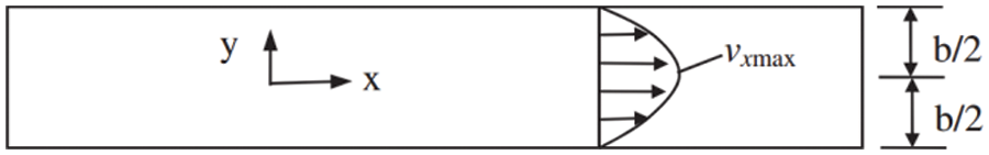
Figure 2: Flow performance in equal-width crack
The velocity of the grout in the soil crack can be expressed as Eq. (4):
where p is the grout pressure, vx is the velocity of the grout in the x-direction, μ is the hydrodynamic viscosity coefficient.
Then, the unit discharge of the fluid within the fracture can be expressed as:
where γ is the specific weight of water.
Therefore, the superficial velocity of the flow can be expressed as:
As shown in Fig. 3, the superficial velocity vector for inclined fractures can be expressed as:
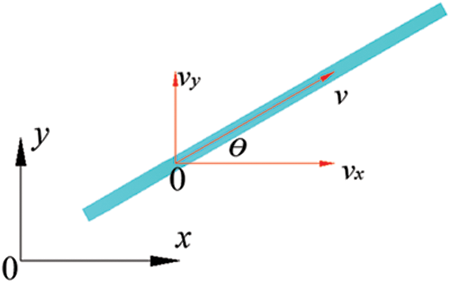
Figure 3: Decomposition of superficial velocity
(2) The viscosity and modulus of grout
During the fracture grouting, the modulus and viscosity of the grout increase nonlinearly under the influence of hydration. Experimental study shows that the Young’s modulus and the viscosity of grout varied gradually, see Eqs. (9) and (10).
where Eg(t) is the Young’s modulus of the grout, μg(t) is the viscosity coefficient of the grout, μg0 is the initial viscosity coefficient of the grout, and t is the hydration time.
The permeability coefficient of the grout in soil within a certain time can be calculated by Eq. (11):
where kg0 is the initial permeability coefficient of grout in soil.
2.2.3 Heterogeneity of Soil Strength
Considering the inhomogeneity of soil strength. The material properties of soil elements obey Weibull distribution in numerical calculation.
where x is the scale parameter representing a certain material property,
2.2.4 Model Setup and Verification
To validate the numerical method, a simulation model of 6 m × 6 m was established. The soil mass within the simulated area is under the plane strain boundary condition, see Fig. 4 below. There are 14,800 elements and 7,605 nodes in the numerical model. The mesh uses triangular elements. The working condition is fracture grouting in clay soil with a buried depth of 5 m. The pressure of grouting is 0.5 MPa. The simulation of the grouting depth was achieved by adjusting the upper load σv in the model.
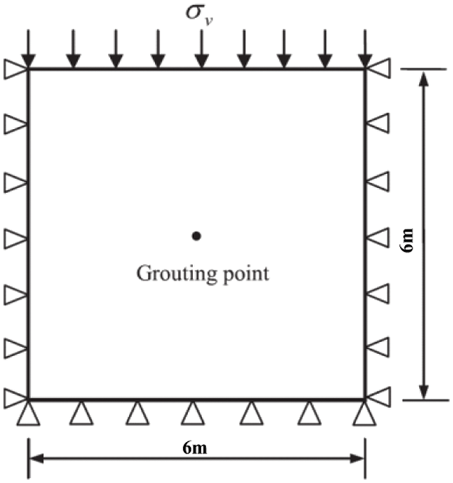
Figure 4: Numerical model
At the same time, fracture grouting test was carried out in an underground engineering. Fracture grouting site excavation test and the corresponding numerical simulation results are shown in Fig. 5. It can be seen from the figure that the numerical simulation result is highly consistent with the experimental results. This shows that the numerical simulation method is reliable to simulate fracture grouting in clay.
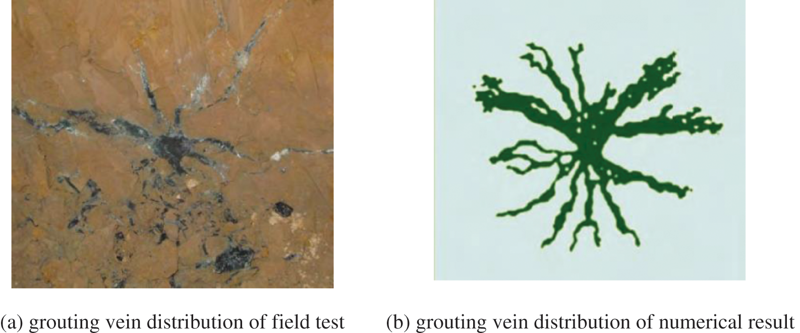
Figure 5: Comparison of field test and numerical simulation results
2.3 Simulated Reinforcement Effect Display
The numerical simulation method based on FEM/VOF method can simulate the fracture grouting diffusion process and record the minor principal stress change process during grouting. Fig. 6 is a cloud diagram of the minor principal stress of the soil before and after fracture grouting. It can be seen that the minor principal stress of the formation before grouting increases from top to bottom with depth, and the distribution is relatively uniform. After the grouting finished, the minor principal stress gradually decreases from the grouting hole to the outside.
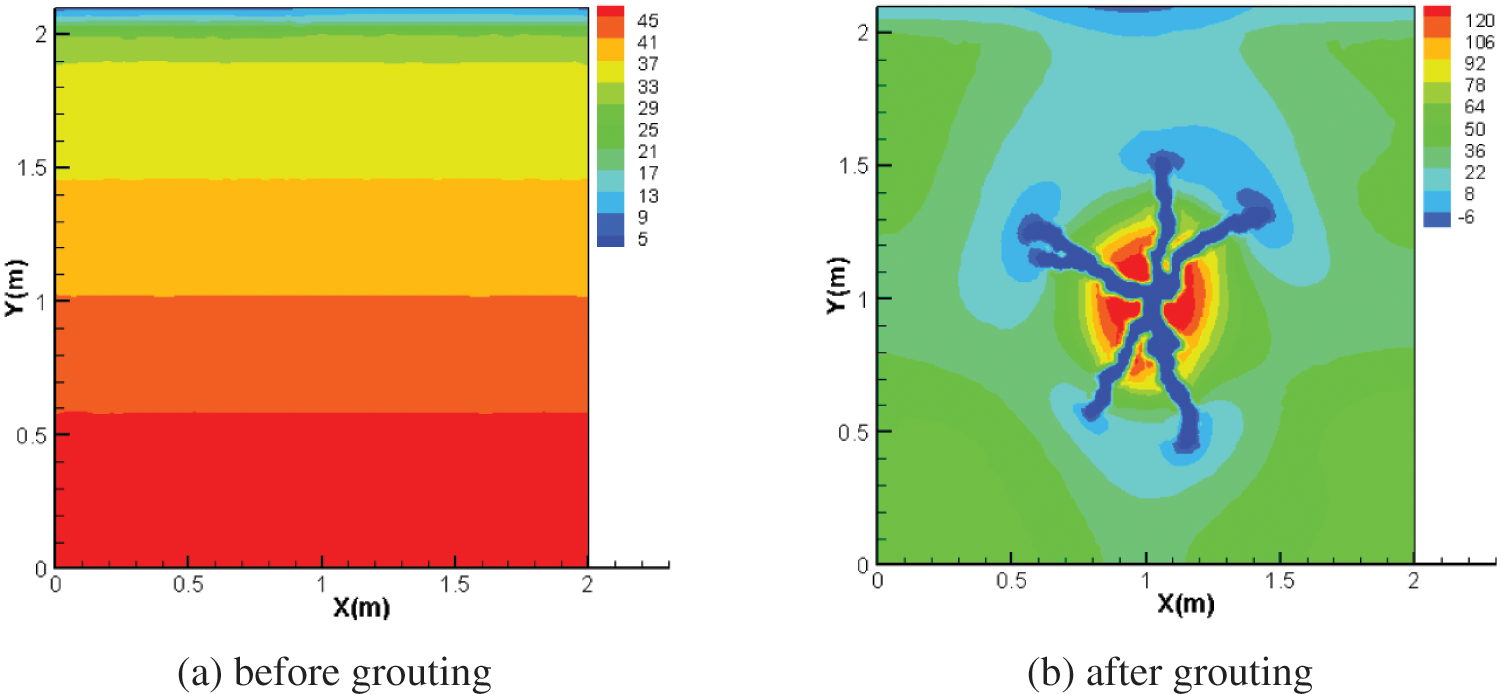
Figure 6: Minimum principal stress distribution of soil before and after grouting(kPa)
According to the Duncan-Chang hyperbolic constitutive model and related parameters, the tangent deformation modulus of the soil element before and after grouting can be calculated by the minor principal stress of the soil layer, see Eq. (13). Duncan-Chang hyperbolic constitutive model material parameters, see Table 1. The minor principal stress at the grouting vein is negative, and its modulus is determined by the grouting material not the Duncan-Chang model.

We select the soil element within the range of 1 m × 1 m near the grouting hole as the research object. Then use Eq. (13) to calculate the soil element modulus, as shown in Fig. 7. The distribution of soil element modulus is the same as that of minor principal stress. The red part in Fig. 7b is the grouting vein skeleton with a certain rigidity formed after the slurry solidified. The grouting material in the simulation is ultra-fine cement slurry. It can be seen from the simulation results that the compaction of the grout increases the modulus of the soil around the grouting hole, and the high-strength grouting vein skeleton can also play a particular role in supporting the soil. They increase the strength of the grouting composite soil together.
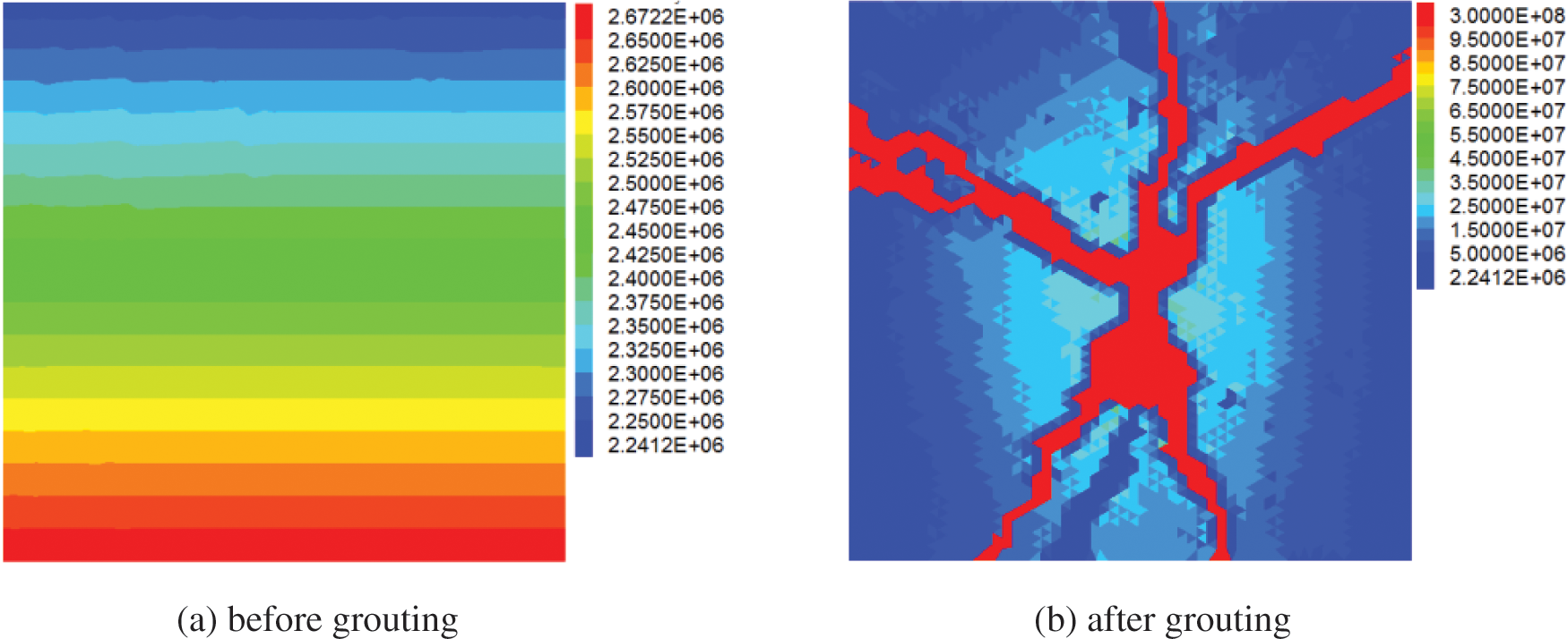
Figure 7: Soil modulus before and after grouting (kPa)
3 Analysis of Reinforcement Effect of Fracture Grouting Composite Soil
The improvement of the compressive modulus of grouting composite soil is one of the methods for evaluating the effect of grouting reinforcement. The shape of the grouting veins in the composite soil is random. The variety of grouting vein shapes increases the difficulty of calculating the compressive modulus of grouting composite soil. Scholars conduct research by simplifying the morphology of the grouting veins. Qian [23] simplified the shape of the grouting veins into two vertical and horizontal forms. Guo et al. [24] simplified the shape of the grouting veins into a crisscross form. A calculation model for grouting composite soil was established based on the shape of actual grouting veins here.
3.1 Confined Compression Test Model
The reinforcement radius of a single grouting hole is generally about 1 m. So we selected the fracture grouting composite soil within the 1 m × 1 m rectangle around the grouting hole as the research object. The calculation model was established as shown in Fig. 8. By applying vertical stress on the top of the model, the settlement curve of the grouting composite soil under different stresses can be obtained. The confined compression test can be simulated by applying displacement loads on the top of the model. The compressive modulus of grouting composite soil can be obtained through the ε ∼ p curve. During the compression test simulation, a displacement velocity of 10e−7 m/step applied to the top of the model. By counting the average stress of the top after each loading level, the compressive modulus of the composite soil can be obtained according to the following formula:
where Δp is the additional stress difference, ΔH is the vertical deformation difference of the composite soil, and H0 is the initial height of the composite soil.
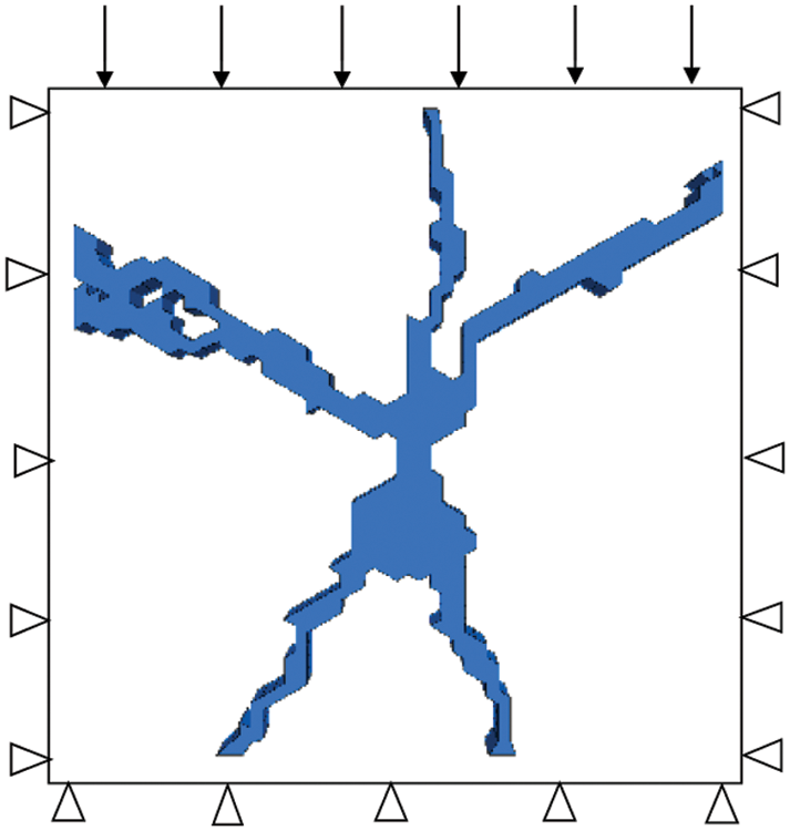
Figure 8: Model scheme of composite soil
The material parameters of soil and grouting vein are shown in Table 2.

To analyze the relationship between grouting pressure, grouting depth, soil parameters, and the composite soil compressive modulus, a series of research conditions were set up, see Table 3.

3.2 Deformation Characteristics of Fracture Grouting Composite Soil under Load
Vertical displacement distribution of undisturbed soil before grouting and composite soil after grouting under a vertical load of 150 kPa, see Fig. 9. The vertical displacement of the undisturbed soil under the vertical load gradually decreases from top to bottom, and the settlement of each level is the same. The vertical settlement value of the grouting composite soil reduced under the same load compared with the undisturbed soil. The compacting effect and skeleton effect of fracture grouting have played reinforcing and reducing deformation effects.
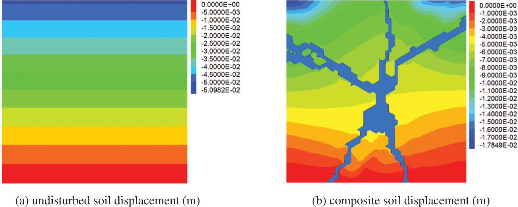
Figure 9: Displacement contours of the original soil and composite soil under 150 kPa vertical load
The vertical displacement curves of the ground surface before and after grouting under different loads are shown in Fig. 10. Under the action of vertical load, the surface settlement of the grouting composite soil is smaller than that of the undisturbed soil. With the increase of the vertical stress, the settlement above the grouting hole decreases more obviously. Fracture grouting greatly improves the strength and resistance to deformation of the soil.
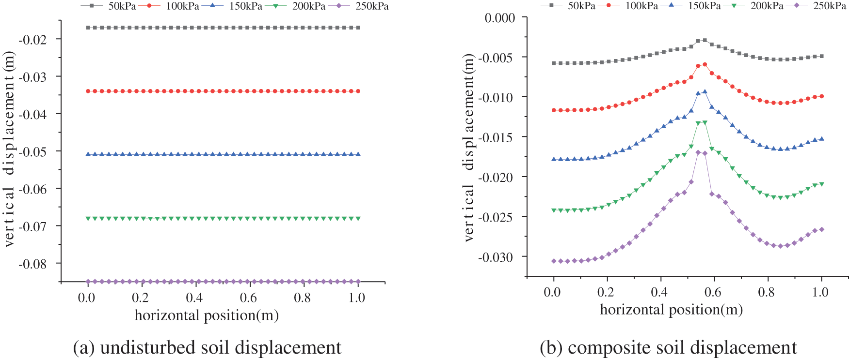
Figure 10: Displacement curves of the original soil and composite soil under different vertical loads
The upper settlement curve of grouting composite soil when considering different reinforcement factors, see Figs. 11 and 12. While only considering the skeleton efect, the settlement above the grouting veins significantly reduced, and the reinforcement area is relatively small. When only considering the compaction effect, the settlement displacement is smaller, the reinforcement area is larger, and the settlement deformation of the composite soil is relatively uniform.
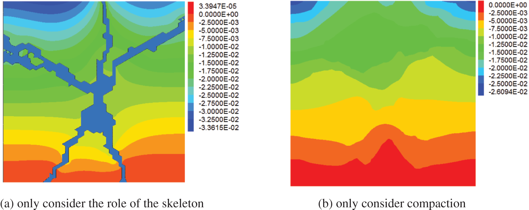
Figure 11: Displacement contours of composite soil when considering different factors
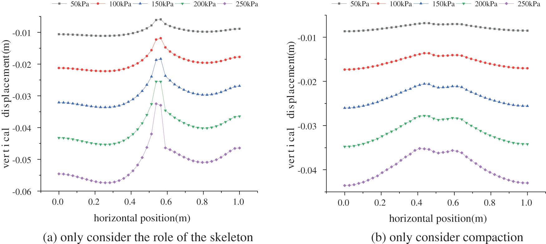
Figure 12: Displacement curves of composite soil considering different reinforcement effects
3.3 Weight Analysis of Compaction and Skeleton Support
To study the weight of the compaction and grouting vein skeleton effects on the composite soil modulus, we established three working conditions: only considering the skeleton effect, only considering the compaction effect, and considering the two effects. The weight of the grouting vein skeleton effect is calculated as follows:
where ωg is the weight of the grouting vein skeleton, Eg+c is the composite soil modulus considering both the skeleton and the compaction effect, Eg is the composite soil modulus considering only the skeleton effect, E0 is the initial modulus of the soil before grouting.
The weight of the compaction effect ωc is:
The calculation results of the previous set of numerical simulation according to Eqs. (15) and (16) are shown in Table 4. It can be seen that the soil modulus after fracture grouting is increased by 223.2% compared with that before grouting. The skeleton effect increases the initial modulus of the soil by 93.9%; the compaction effect increases the initial modulus of the soil by 129.3%. In this set of calculations, the compaction effect plays a leading role in the fracture grouting reinforcement. The weight of the skeleton effect in the grouting reinforcement effect is: ωg = 2.76/6.56 = 42.07%; the weight of the compaction effect is: ωc = 3.8/6.56 = 57.93%. To find out which reinforcement effect of fracture grouting plays a leading role, Further statistical analysis of reinforcement weights under different grouting pressures and depths are needed to find out which one plays the leading role.

The weight of the compaction effect and the skeleton effect in the grouting reinforcement under different grouting depths, grouting pressures, and the initial modulus of the soil, see Fig. 13. Only two out of the 64 sets of statistical results show that skeleton support weights exceed 50%, and the other 62 sets show that the compaction effect has played a leading role. The weight of the skeleton action decreases with the increase of the initial modulus of the soil. The grouting vein skeleton has a better effect in soft soil.
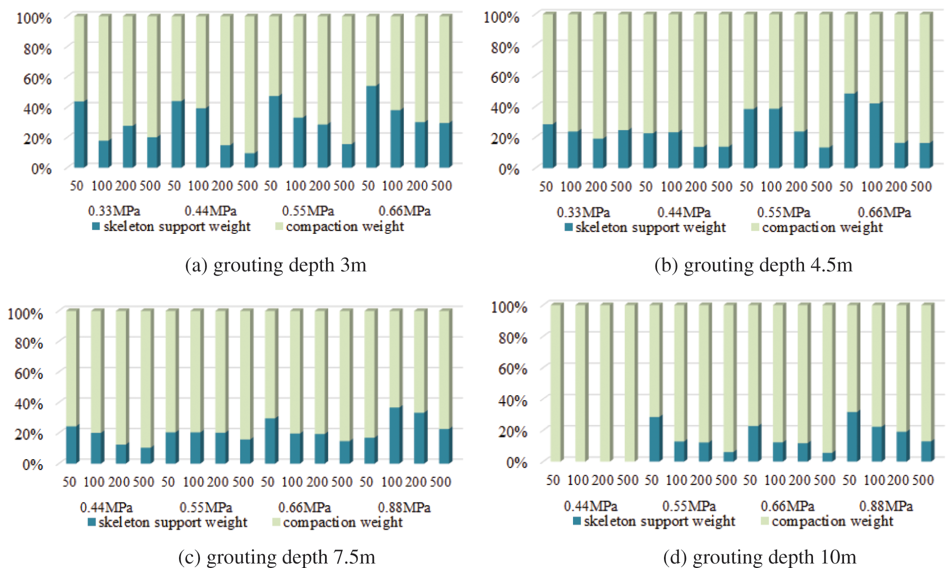
Figure 13: Reinforcement factor weight analysis
4 Influencing Factors on Compression Modulus of Composite Soil
The fracture grouting composite soil comprises two solid media: the grouting vein skeleton and the soil. The shape of the grouting vein, the modulus of the soil after grouting, and the modulus of the grouting vein skeleton will all affect the compressive modulus of composite soil. According to the simulation working conditions designed in Table 2, the FEM/VOF numerical method was used to obtain the grouting vein shapes and minor principal stress distribution. The shape of the grouting vein, the modulus of the surrounding soil, and the grouting vein skeleton were imported into the confined compression test model. Considering the randomness of the shape of the grouting vein, three sets of calculations were carried out for each working condition. The average value was taken as the composite soil modulus for each working condition. The soil material is assigned randomly following the Weibull distribution.
4.1 Grouting Pressure and Compressive Modulus of Composite Soil
The relationship between composite soil compressive modulus and grouting pressure, see Fig. 14. The parameter K corresponds to different soil modulus, and the soil modulus increases with the increase of K value. It can be found that the compressive modulus of the composite soil increases with the grouting pressure. The rises of modulus is more apparent when the initial soil modulus is relatively large. It shows that fracture grouting has a more obvious reinforcement effect in hard soil.
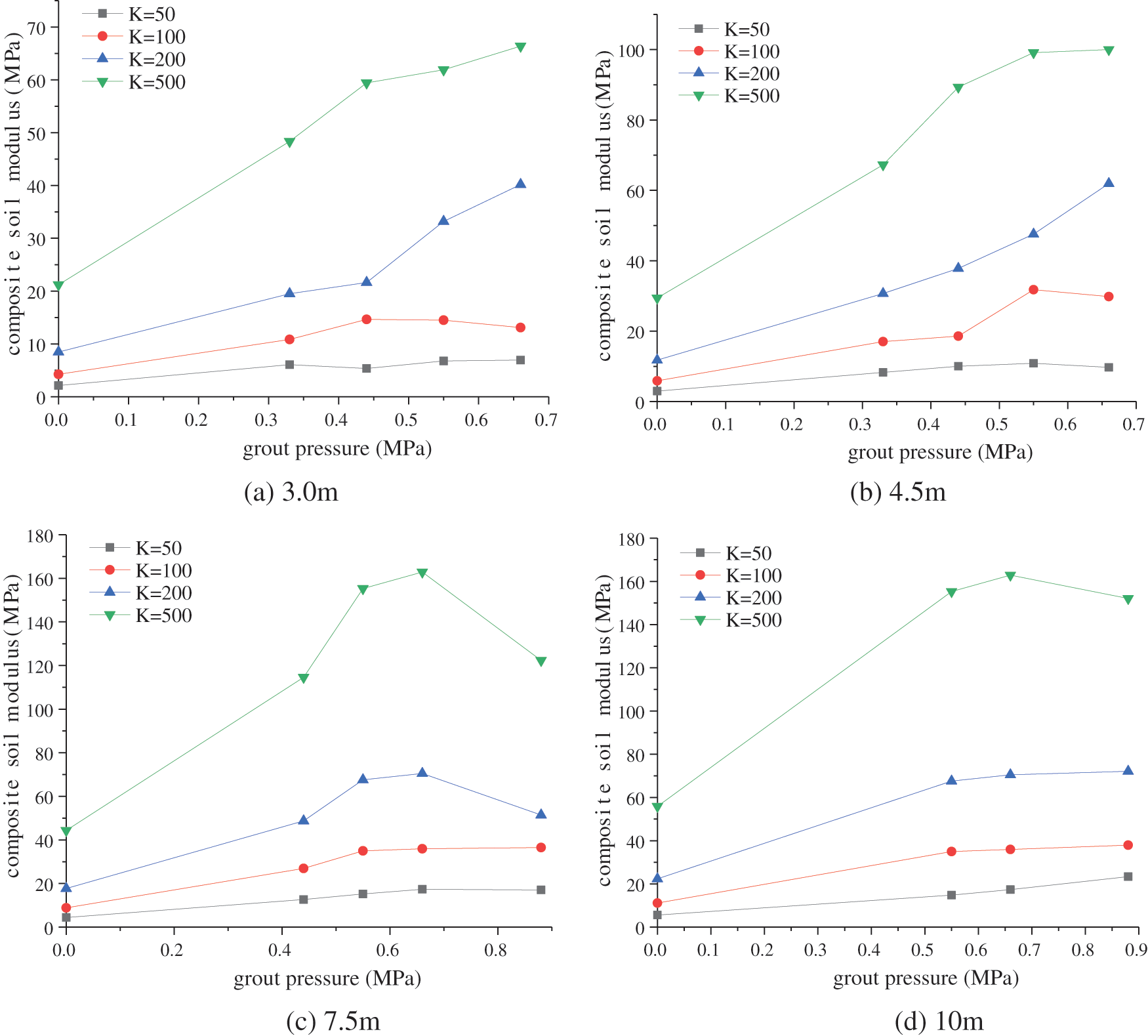
Figure 14: Relationship between grouting pressure and composite soil compressive modulus
With the increase of grouting pressure, the modulus of composite soil tends to stabilize. The soil reinforcement effect will not increase or increase slowly when the grouting pressure increases to a certain extent. It is not that the greater the grouting pressure, the better the reinforcement effect. Excessive grouting pressure will cause deformation and damage, thereby reducing the reinforcement effect. The recommended grouting pressure in the soil can be given in conjunction with Fig. 14. When the grouting depth is 3 and 4.5 m, the recommended grouting pressure does not exceed 0.5 MPa. When the grouting depth is 7.5 m, the recommended grouting pressure does not exceed 0.7 MPa. When the grouting depth is 10 m, the grouting pressure is recommended not to exceed 1.0 MPa.
Grouting pressure can influence the spreading range and branches of the grouting vein. The relationship between the grouting pressure and the weight of the grouting vein skeleton, see Fig. 15. With the increase of grouting pressure, the overall weight of the skeleton action shows an increasing trend. The softer the soil, the greater the weight of the skeleton is. It is because the compaction effect in the soft soil is not apparent, and the grouting vein branches strengthen the skeleton effect. For relatively hard soil (such as when K = 200 and K = 500), increasing the grouting pressure will increases the compaction effect of the soil first. Although the skeleton effect is also strengthened, it is only when the soil is compacted to a certain extent. In general, increasing the grouting pressure in soft soils will increase the weight of the skeleton action. While increasing the pressure in the relatively hard soil, the weight of the skeleton action first decreases and then increases. Because in the hard soil, the weight of the skeleton effect will grow only when the compaction effect reaches a particular level.
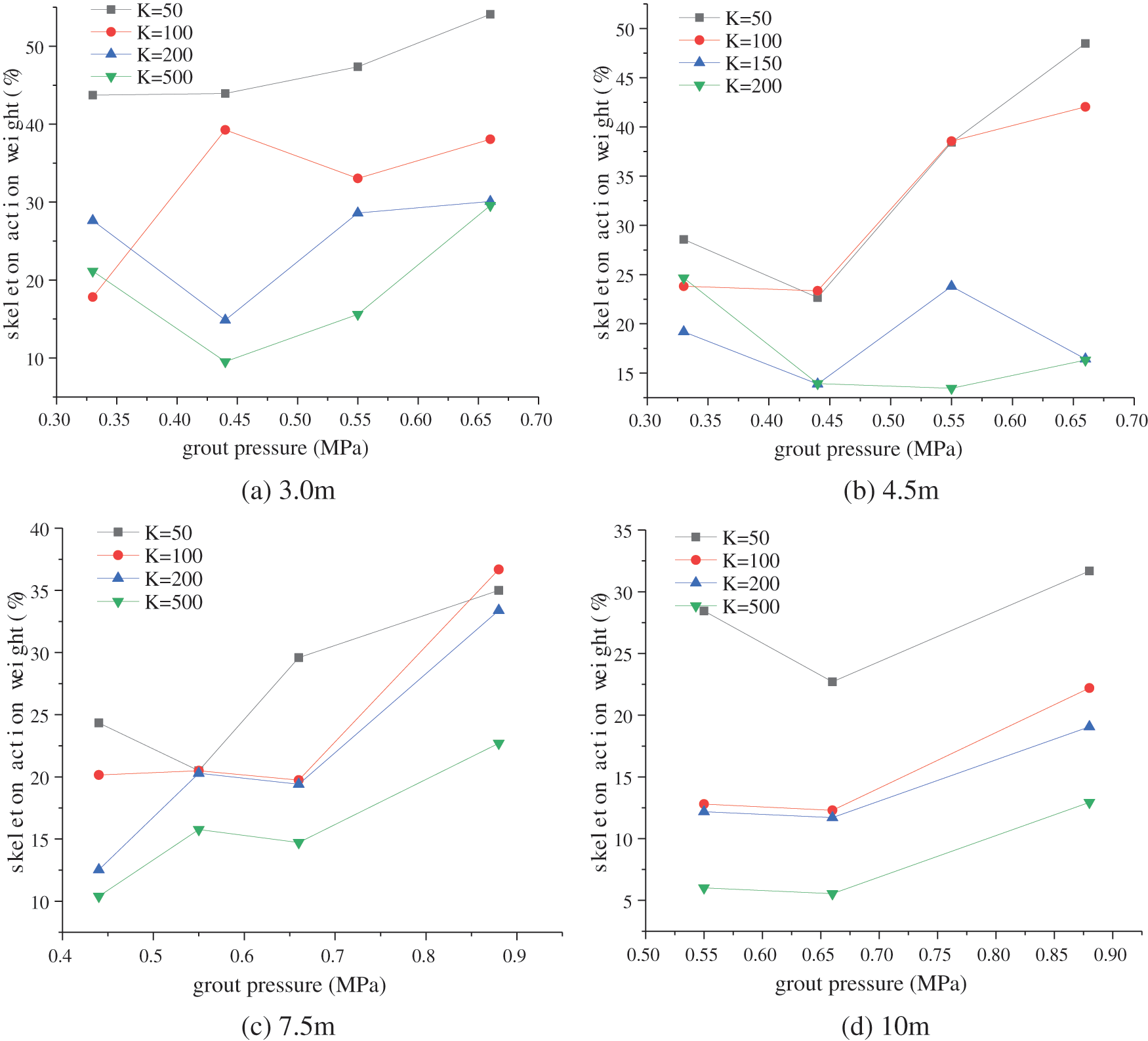
Figure 15: Grouting pressure and grout skeleton action weight
4.2 Grouting Vein Modulus and Composite Soil Compressive Modulus
After fracture grouting, the slurry hardens to form grouting veins with a certain strength. The grouting veins play the role of skeleton support in the soil. It can also improve the strength and resistance to deformation of the soil. The modulus of the grouting vein skeleton will affect the modulus of the composite soil, see Fig. 16. It can be seen that the compressive modulus of the composite soil increases with the increase of the grouting vein skeleton modulus. When the modulus of the grouting vein skeleton increases to 500 MPa, the contribution rate to the rise of the composite modulus gradually decreases.
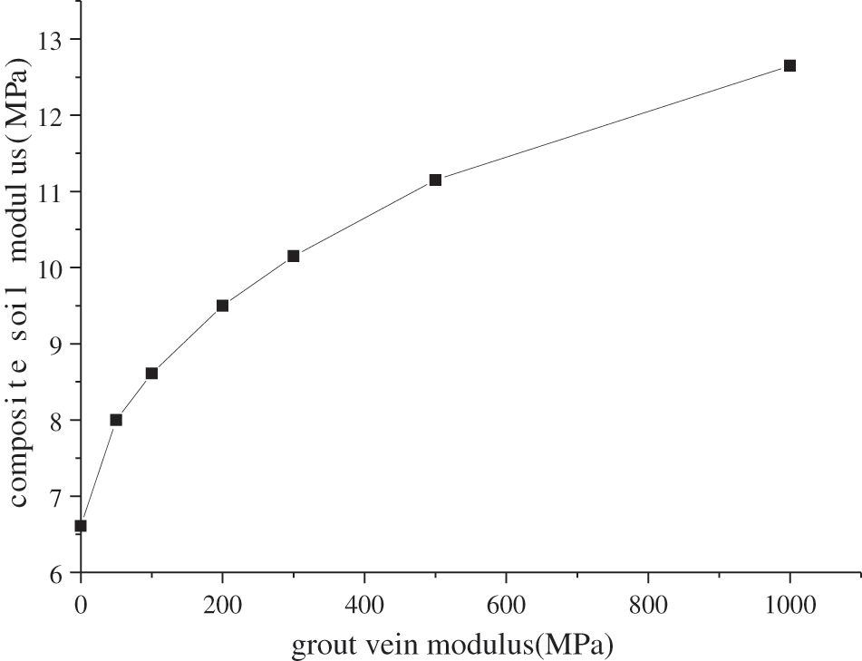
Figure 16: Relationship between skeletal modulus and composite soil modulus
With the skeleton modulus increases, the weight of the skeleton action increases, see Fig. 17. The weight of the skeleton action increases significantly when the grouting vein skeleton modulus between 50 and 300 MPa. After that, the weight of the skeletal action of the grouting veins tends to stabilize and approach 50%. Therefore, when performing fracture grouting reinforcement in soft soils, it is recommended to choose a grouting material with a skeleton elastic modulus less than 300 MPa after curing.
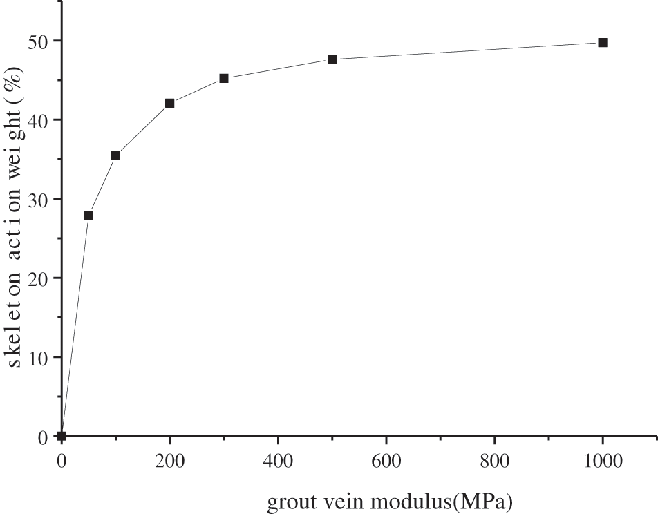
Figure 17: Relationship between grouting vein modulus and skeleton weight
4.3 The Initial Modulus of Soil and Composite Soil Compressive Modulus
The initial modulus of the soil before grouting is related to factors such as soil type and buried depth. It is a parameter that reflects the softness and hardness of the soil. The initial modulus of the soil affects the distribution of the grouting veins and the injection rate of the slurry. The study of the expansion law of single-hole splitting grouting shows that with the increase of soil modulus, the volume of the slurry bubble gradually decreases, the width of the slurry vein becomes narrower, and the grouting rate falls. It will also cause the weight of the skeleton action to fall with the increase of the initial modulus of the soil under the same grouting pressure and other conditions, see Fig. 18.
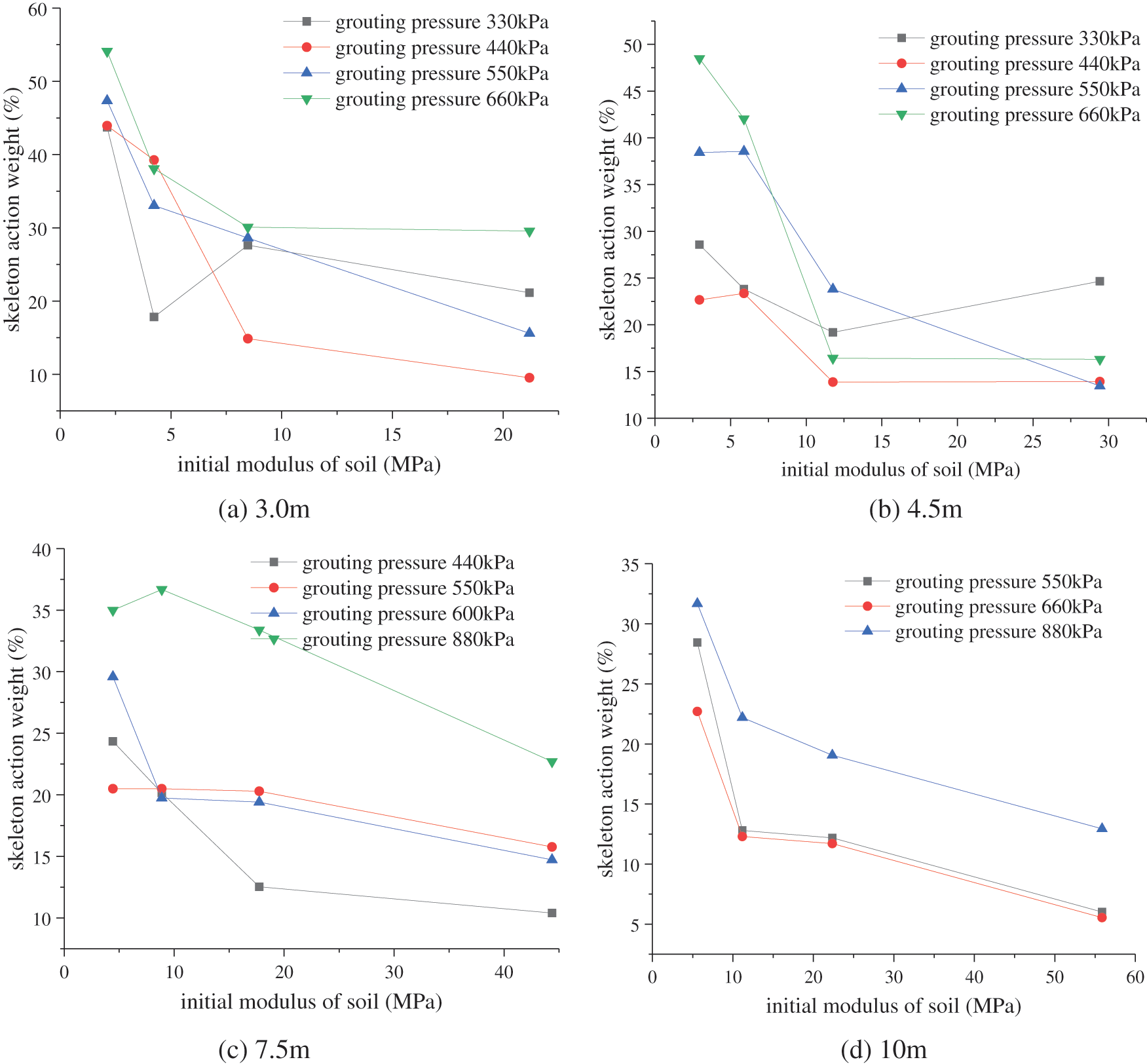
Figure 18: Soil initial modulus and grout skeleton weight
It can be seen that as the initial modulus of the soil increases, the weight of the skeleton action shows a downward trend. The skeleton effect is obvious, and the compaction effect is relatively weak when fracture grouting in soft soil. When fracture grouting in hard soil, the skeleton effect is reduced, and the compaction effect is enhanced.
In this paper, a calculation model of fracture grouting composite soil is established based on the grouting veins of single-hole fracture grouting. The composite soil compressive modulus under different grouting depth, grouting pressure, and initial soil modulus were obtained through a series of compression test simulations. The weight analysis of the fracture grouting reinforcement effect was also carried out. The main conclusions are as follows:
(1) The fracture grouting reinforcement effects include the support effect of the grouting vein skeleton and the compacting effect. Through statistical analysis of 64 sets of calculation results, it is found that the compacting effect plays a leading role in the soil fracture grouting reinforcement.
(2) The compressive modulus of fracture grouting composite soil is affected by the grouting pressure, the initial modulus of the soil, and the strength of the grouting vein skeleton.
(3) With the increase of grouting pressure, the compressive modulus of composite soil increases continuously. However, there is an optimal pressure value for fracture grouting reinforcement, not that the bigger the pressure, the better the effect.
(4) With the increase of the grouting vein skeletal modulus, the composite soil compressive modulus and the weight of the skeletal action gradually increase. When the elastic modulus of the grouting vein in soft soil is greater than a certain level, the support effect of the skeleton does not increase significantly.
Funding Statement: This work was financially supported by the National Key R&D Plan of China (No. 2017YFC0805400).
Conflicts of Interest: The authors declare that they have no conflicts of interest to report regarding the present study.
1. Bai, Y., Hou, X. Y. (1991). Mechanism and application of grouting reinforcement of soft foundation. Chinese Journal of Geotechnical Engineering, 13(2), 89–93. DOI 10.3321/j.issn:1000-4548.1991.02.010. [Google Scholar] [CrossRef]
2. Nichols, S. C., Goodings, D. J. (2000). Physical model testing of compaction grouting in cohesionless soil. Journal of Geotechnical and Geoenvironmental Engineering, 126(9), 848–852. DOI 10.1061/(ASCE)1090-0241(2000)126:9(848). [Google Scholar] [CrossRef]
3. Zhou, S. M., Chen, J. J. (2002). Hydro-fracture grouting in soft flowing mucky ground for a metro tunnel. Chinese Journal of Geotechnical Engineering, 24(2), 222–224. DOI 10.3321/j.issn:1000-4548.2002.02.021. [Google Scholar] [CrossRef]
4. Fransson, A., Tsang, C. F., Rutqvist, J., Gustafson, G. (2007). A new parameter to assess hydromechanical effects in single-hole hydraulic testing and grouting. International Journal of Rock Mechanics & Mining Sciences, 44(7), 1011–1021. DOI 10.1016/j.ijrmms.2007.02.007. [Google Scholar] [CrossRef]
5. Li, Z. P., Li, S. C., Liu, H. J., Zhang, Q. S., Liu, Y. N. (2018). Experimental study on the reinforcement mechanism of segmented split grouting in a soft filling medium. Processes, 6(8), 131. DOI 10.3390/pr6080131. [Google Scholar] [CrossRef]
6. Chang, M., Mao, T., Huang, R. (2016). A study on the improvements of geotechnical properties of in-situ soils by grouting. Geomechanics and Engineering, 10(4), 527–546. DOI 10.12989/gae.2016.10.4.527. [Google Scholar] [CrossRef]
7. Toru, T., Hirakazu, S., Tatsunori, M., Mamoru, F., Taizou, O., et al. (2010). Field tests on improvement effects of fracture grouting in residential areas. Architectural Institute of Japan Journal of Technology and Design, 16, 483–488. DOI 10.3130/aijt.16.483. [Google Scholar] [CrossRef]
8. Wang, H. B., Zhang, Q. S., Liu, R. T., Li, S. C., Zhang, L. W. et al. (2017). Grouting reinforcement mechanism and experimental study of cement quick-setting slurry infiltration. IOP Conference Series: Earth and Environmental Science, 81, 012025. DOI 10.1088/1755-1315/81/1/012025. [Google Scholar] [CrossRef]
9. Lan, X. D., Zhang, X., Li, X. H., Zhang, J. Q., Zhou, Z. (2020). Experimental study on grouting reinforcement mechanism of heterogeneous fractured rock and soil mass. Geotechnical and Geological Engineering, 38, 4949–4967. DOI 10.1007/s10706-020-01338-x. [Google Scholar] [CrossRef]
10. Hsiao, D. H., Phan, V. T. A., Huang, C. C. (2016). An experimental investigation on dynamic properties of various grouted sands. Geomechanics and Engineering, 10(1), 77–94. DOI 10.12989/gae.2016.10.1.077. [Google Scholar] [CrossRef]
11. Niu, J. D., Li, Z. W., Gu, W. H., Chen, K. (2020). Experimental study of split grouting reinforcement mechanism in filling medium and effect evaluation. Sensors, 20(11), 3088. DOI 10.3390/s20113088. [Google Scholar] [CrossRef]
12. Eriksson, M., Stille, H., Andersson, J. (2000). Numerical calculations for prediction of grout spread with account for filtration and varying aperture. Tunnelling and Underground Space Technology Incorporating Trenchless Technology Research, 15(4), 353–364. DOI 10.1016/S0886-7798(01)00004-9. [Google Scholar] [CrossRef]
13. Moës, N., Belytschko, T. (2002). Extended finite element method for cohesive crack growth. Engineering Fracture Mechanics, 69, 813–833. DOI 10.1016/S0013-7944(01)00128-X. [Google Scholar] [CrossRef]
14. Pantuso, D., Jiang, L., Shankar, S., Skokov, S. (2003). A FEM/VOF hybrid formulation for underfill encapsulation modeling. Computers & Structures, 81, 879–885. DOI 10.1016/S0045-7949(02)00419-4. [Google Scholar] [CrossRef]
15. Lecampion, B. (2009). An extended finite element method for hydraulic fracture problems. Communications in Numerical Methods in Engineering, 25, 121–133. DOI 10.1002/cnm.1111. [Google Scholar] [CrossRef]
16. Carrier, B., Granet, S. (2012). Numerical modeling of hydraulic fracture problem in permeable medium using cohesive zone model. Engineering Fracture Mechanics, 79, 312–328. DOI 10.1016/j.engfracmech.2011.11.012. [Google Scholar] [CrossRef]
17. Sarris, E., Papanastasiou, P. (2013). Numerical modeling of fluid-driven fractures in cohesive poroelastoplastic continuum. International Journal for Numerical and Analytical Methods in Geomechanics, 37(12), 1822–1846. DOI 10.1002/nag.2111. [Google Scholar] [CrossRef]
18. Koyama, T., Katayama, T., Tanaka, T., Kuzuha, Y., Ohnishi, Y. (2013). Development of a numerical model for grout injection and its application to the in situ grouting test at the grimsel test site, Switzerland. Geosystem Engineering, 16(1), 26–36. DOI 10.1080/12269328.2013.780766. [Google Scholar] [CrossRef]
19. Guo, Y. X., Zhao, P., Zhang, Q. S., Liu, R. T., Zhang, L. Z. et al. (2019). Investigation of the mechanism of grout penetration in intersected fractures. Fluid Dynamics & Materials Processing, 15(4), 321–342. DOI 10.32604/fdmp.2019.07844. [Google Scholar] [CrossRef]
20. Suri, Y., Islam, S. Z., Hossain, M. (2020). Numerical modelling of proppant transport in hydraulic fractures. Fluid Dynamics & Materials Processing, 16(2), 297–337. DOI 10.32604/fdmp.2020.08421. [Google Scholar] [CrossRef]
21. Chen, T. L., Zhang, L. Y., Zhang, D. L. (2014). An FEM/VOF hybrid formulation for fracture grouting modelling. Computers and Geotechnics, 58, 14–27. DOI 10.1016/j.compgeo.2014.02.002. [Google Scholar] [CrossRef]
22. Cheng, S. Z., Chen, T. L., Guo, W. Q., Zhang, Y. (2019). Numerical simulation of fracture grouting and influencing factors for morphology of grout veins. Chinese Journal of Geotechnical Engineering, 41(3), 484–491. DOI 10.11779/CJGE201903010. [Google Scholar] [CrossRef]
23. Qian, B. Y. (2007). Computation of compression modulus for fracture grouting of soft clay. Journal of Ningbo University, 20(3), 385–387. DOI 10.3969/j.issn.1001-5132.2007.03.025. [Google Scholar] [CrossRef]
24. Guo, Y. W., He, S. H., Zhang, A. K., Wang, D. H. (2016). A three-dimensional equivalent elastic model of composite soils with fracture grouting. Rock and Soil Mechanics, 37(7), 1877–1886. DOI 10.16285/j.rsm.2016.07.007. [Google Scholar] [CrossRef]
 | This work is licensed under a Creative Commons Attribution 4.0 International License, which permits unrestricted use, distribution, and reproduction in any medium, provided the original work is properly cited. |